EP0933838A1 - Einsatz zur Verwendung in einer Steckdose - Google Patents
Einsatz zur Verwendung in einer Steckdose Download PDFInfo
- Publication number
- EP0933838A1 EP0933838A1 EP99102045A EP99102045A EP0933838A1 EP 0933838 A1 EP0933838 A1 EP 0933838A1 EP 99102045 A EP99102045 A EP 99102045A EP 99102045 A EP99102045 A EP 99102045A EP 0933838 A1 EP0933838 A1 EP 0933838A1
- Authority
- EP
- European Patent Office
- Prior art keywords
- insert
- socket
- plug
- lateral surface
- recess
- Prior art date
- Legal status (The legal status is an assumption and is not a legal conclusion. Google has not performed a legal analysis and makes no representation as to the accuracy of the status listed.)
- Granted
Links
- 230000001681 protective effect Effects 0.000 claims description 7
- 238000005452 bending Methods 0.000 description 2
- 238000004519 manufacturing process Methods 0.000 description 2
- 239000002184 metal Substances 0.000 description 2
- 229920001875 Ebonite Polymers 0.000 description 1
- 238000010276 construction Methods 0.000 description 1
- 230000005611 electricity Effects 0.000 description 1
- 239000000463 material Substances 0.000 description 1
- 230000002093 peripheral effect Effects 0.000 description 1
- 230000006641 stabilisation Effects 0.000 description 1
- 238000011105 stabilization Methods 0.000 description 1
Images
Classifications
-
- H—ELECTRICITY
- H01—ELECTRIC ELEMENTS
- H01R—ELECTRICALLY-CONDUCTIVE CONNECTIONS; STRUCTURAL ASSOCIATIONS OF A PLURALITY OF MUTUALLY-INSULATED ELECTRICAL CONNECTING ELEMENTS; COUPLING DEVICES; CURRENT COLLECTORS
- H01R31/00—Coupling parts supported only by co-operation with counterpart
- H01R31/06—Intermediate parts for linking two coupling parts, e.g. adapter
Definitions
- the present invention relates to an insert for use in a cup-shaped one Recess for a two-pin plug provided AC outlet, the is provided with two pole pieces sunk in the base of the recess.
- Plug connections consist of the socket and the plug.
- the so-called Schuko plugs are available as plugs on the market have it plugged into the socket.
- Another connector on the market is the so-called flat plug, also called the Euro plug, which is flat on its narrow sides runs in and positioned in the socket in the form of a groove in the socket becomes.
- Some electrical devices can only be operated with direct current, the alternating current is converted into direct current from the socket via transformers. With these Devices are often attached directly to the transformer. The weight of the transformers weighs on the connection between plug and socket.
- Interruptions in the power supply are not only harmful for the connected ones Devices, especially if data processing systems are connected, can also there is data loss that can be very damaging to individual companies.
- the present invention had for its object to develop a device that enables the plug in the socket or socket to be fixed in plug connections To give hold, whereby inaccuracies in the manufacture can be avoided.
- the contact between the plug and the socket or outlet (in following only referred to as the socket) stabilizes and interruptions in the power supply by not fitting plugs are avoided.
- the use according to the invention is for all flat plugs and plug-in power supplies with a flat plug connection suitable. It preferably consists of a material that does not conduct electricity like plastic or hard rubber. It enables a tight fit of flat plugs and avoids especially in the case of plug-in power supplies with a flat plug connection the socket.
- the sockets currently used have protective contacts in their scope.
- the use according to the invention is configured in the first, lateral surface a groove for receiving these protective contacts.
- the use according to the invention is combined with a further, identically designed insert used, which forms a double insert and itself Between the two insert halves thus formed, there is a space for the housing of the tab connector located. With this configuration, the tab is firmly in the socket fixed. Another advantage is that the socket is completely filled, so that too Dangers caused by careless handling of metal objects near Sockets can be minimized.
- the two insert halves are firmly connected to one another. It has proven to be particularly suitable for the two insert halves to be connected to one another via a plate to connect, which when used in the socket at the base of the recess of the Can fits.
- the plate should be provided with two openings or cutouts that can protrude through the pole of the tab.
- This embodiment has the advantage that it is permanently attached to the socket be and can remain there when changing the plug.
- This use can also be permanent be connected to the plug itself and is then together with this in the socket inserted.
- permanent means that the use is constantly in the socket, this is a plug connection acts that is solvable.
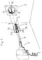
- Figure 1 is an arrangement of a power supply with a flat connector 1, inventive Insert 2 and socket 3 shown.
- the insert 2 is formed by the two insert parts 2a and 2b, which are connected by a plate 4 are interconnected.
- the plate 4 has two recesses 5a and 5b, in which the Pin pins 6 of the plug-in power supply with flat plug connection 1 are inserted.
- the insert parts 2a and 2b also have cutouts 7a and 7b, which the protective contacts 8 of the Take socket 3.
- the projections 9a and 9b on the plate 4 are removed from the groove 10 in the socket 3 added.
- the plug-in power supply sits due to the construction shown here with the flat plug 1 firmly in the socket 3.
- the falling out of the relatively heavy Power supply and the bending of plug contacts due to the weight of the plug-in power supply this stabilization in the socket itself is avoided.
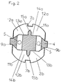
- FIG. 2 shows a top view of the insert 2 according to the invention shown in FIG. 1, which forms a double insert from two insert parts 2a, 2b.
- the insert parts 2a and 2b are connected to each other via a plate 4.
- the plate has two cutouts 5a, 5b, through which the pole pins 6 of the plug 1 can be inserted.
- the two insert parts 2a and 2b form a free space between them which corresponds to the shape of the housing Has flat connector 1.
- the insert points in the outer lateral surface 11a, 11b a recess 7a, 7b, which is arranged to receive the in the usual sockets Protective contacts 8 is used.
- a part protrudes on the inside that a groove to prevent rotation of the plug.
- the plate 4 formed such that two projections 9a, 9b in the formed by the insert parts 2a and 2b Stand out space, which when used in socket 3 in the socket wall located groove 10 can be fitted. With this embodiment, the hold the use according to the invention in the socket can be further improved.
- the insert parts 2a and 2b additionally show in the upper surface 12a, 12b or that of the upper surface 12a, 12b and the inner one
- the lateral surface 13a, 13b formed edge 14a, 14b each have a recess 15a, 15b.
- the insert can be removed from the tool with the aid of a tool Pull out socket 3.
- the two Recesses 15a, 15b at such a distance that the pole pins 6 of the flat connector 1st can be inserted and by slightly rotating or pulling the inventive Insert 1 can be removed from the socket 3.
Landscapes
- Connector Housings Or Holding Contact Members (AREA)
- Details Of Connecting Devices For Male And Female Coupling (AREA)
- Coupling Device And Connection With Printed Circuit (AREA)
- Cable Accessories (AREA)
- Cartons (AREA)
- Insulating Bodies (AREA)
- Non-Disconnectible Joints And Screw-Threaded Joints (AREA)
- Control Of Driving Devices And Active Controlling Of Vehicle (AREA)
Abstract
Description

- Fig. 1
- Eine Explosionsdarstellung von Flachstecker, erfindungsgemäßem Einsatz und Steckdose
- Fig. 2
- Eine Draufsicht auf den erfindungsgemäßen Einsatz bestehend aus zwei Einsatzteilen, die über eine Platte miteinander verbunden sind.
- 1
- Steckernetzteil mit Flachsteckeranschluß
- 2
- Einsatz
- 2a, 2a
- einzelnes Einsatzteil
- 3
- Steckdose
- 4
- Platte
- 5a, 5b
- Öffnung in Platte 4 zur Aufnahme der Polstifte
- 6
- Polstifte
- 7a, 7b
- Aussparung im Einsatzteil 2a, 2b zur Aufnahme der Schutzkontakte
- 8
- Schutzkontakt
- 9a, 9b
- Vorsprung an Platte 2
- 10
- Nut
- 11a, 11b
- äußere Mantelfläche
- 12a, 12b
- obere Fläche
- 13a, 13b
- innere Mantelfläche
- 14a, 14b
- Kante
- 15a, 15b
- Aussparung in der Kante 14
Claims (7)
- Einsatz zur Verwendung in einer mit einer topfförmigen Ausnehmung für einen zwei-poligen Stecker (1) versehenen Wechselstrom-Steckdose (3), die mit zwei versenkt in der Basis der Ausnehmung angeordnete Polschuhen versehen ist, wobei der Einsatz (2) aufweist:(a) eine erste, im wesentlichen teilkreisförmig gestaltete Mantelfläche (11a, 11b),(b) eine zweite Mantelfläche (13a, 13b), die zusammen mit der ersten Mantelfläche (11a, 11a) die Umfaßkontur des Einsatzes (2) definiert, wobei zumindest ein Teil der zweiten Mantelfläche (13a, 13b) eine Stützfläche bildet, an der ein in die Steckdose eingesetzter Flachstecker (1) mit einer seiner beide Flachseiten zur Anlage kommt.
- Einsatz nach Anspruch 1, dadurch kennzeichnet, daß er in der ersten, Mantelfläche (11a, 11b) eine Nut (7a, 7b) zur Aufnahme von im Umfang der Steckdose (3) angeordneten Schutzkontakte (8) aufweist.
- Einsatz nach einem der Ansprüche 1 oder 2, dadurch gekennzeichnet, daß er gemeinsam mit einem weiteren, identisch gestalteten Einsatz (2a, 2b) einen Doppeleinsatz bildet, und wobei sich zwischen den beiden so gebildeten Einsatzhälften (2a, 2b) ein Freiraum für das Gehäuse des Flachsteckers (1) befindet.
- Einsatz nach Anspruch 3, dadurch gekennzeichnet, daß die beiden Einsatzhälften (2a, 2b) fest miteinander verbunden sind.
- Einsatz nach Anspruch 4, dadurch gekennzeichnet, daß die beiden Einsatzhälften (2a, 2b) über eine Platte (4) miteinander verbunden sind, die an der Basis der Ausnehmung der Steckdose (3) anliegt.
- Einsatz nach Anspruch 5, dadurch gekennzeichnet, daß die Platte (4) mit zwei Öffnungen oder Aussparungen (5a, 5b) versehen ist, durch die die Polstifte (6) des Flachsteckers (1) hindurchragen.
- Einsatz nach einem der Ansprüche 1 bis 6, dadurch gekennzeichnet, daß sich in der oberen Fläche (12a, 12b) des Einsatzteils (2a, 2b) oder in der von der oberen Fläche 12a, 12b und der inneren Mantelfläche 13a, 13b gebildeten Kante (14a, 14b) eine Aussparung (15a, 15b) zur Aufnahme von Werkzeug befindet.
Applications Claiming Priority (2)
| Application Number | Priority Date | Filing Date | Title |
|---|---|---|---|
| DE29801735U | 1998-02-03 | ||
| DE29801735U DE29801735U1 (de) | 1998-02-03 | 1998-02-03 | Einsatz zur Verwendung in einer Steckdose |
Publications (2)
| Publication Number | Publication Date |
|---|---|
| EP0933838A1 true EP0933838A1 (de) | 1999-08-04 |
| EP0933838B1 EP0933838B1 (de) | 2002-10-23 |
Family
ID=8052091
Family Applications (1)
| Application Number | Title | Priority Date | Filing Date |
|---|---|---|---|
| EP99102045A Expired - Lifetime EP0933838B1 (de) | 1998-02-03 | 1999-02-02 | Einsatz zum Einstecken in einer Steckdose |
Country Status (6)
| Country | Link |
|---|---|
| EP (1) | EP0933838B1 (de) |
| AT (1) | ATE226765T1 (de) |
| DE (2) | DE29801735U1 (de) |
| DK (1) | DK0933838T3 (de) |
| ES (1) | ES2185257T3 (de) |
| PT (1) | PT933838E (de) |
Cited By (2)
| Publication number | Priority date | Publication date | Assignee | Title |
|---|---|---|---|---|
| FR2834135A1 (fr) * | 2001-12-21 | 2003-06-27 | Gavino | Enceinte electrique de contact encastrable et dispositif de montage associe |
| US7114967B2 (en) | 2001-12-21 | 2006-10-03 | Sibecx | Built-in electric contact enclosure and mounting method |
Families Citing this family (1)
| Publication number | Priority date | Publication date | Assignee | Title |
|---|---|---|---|---|
| DE10154905C2 (de) * | 2001-10-30 | 2003-12-18 | N & L Elektrotechnik Gmbh | Rundsteckdoseneinsatz |
Citations (4)
| Publication number | Priority date | Publication date | Assignee | Title |
|---|---|---|---|---|
| DE7405760U (de) * | 1974-02-19 | 1974-05-30 | Kadus Werk Kegel L Kg | Steckvorrichtung (Adapter) für Schutzkontakt-Steckdosen |
| DE8806144U1 (de) * | 1988-05-09 | 1988-07-14 | Isotronic Dieter Mezger, 7407 Rottenburg | Zweipoliger Zwischenstecker mit Schutzleiter |
| DE9202389U1 (de) * | 1992-02-25 | 1992-04-23 | Isotronic Dieter Mezger, 7407 Rottenburg | Steckadapter für Schutzkontaktsteckdosen |
| FR2669472A1 (fr) * | 1990-11-20 | 1992-05-22 | Precia Sa | Entretoise amovible pour transformateurs de courant incorporant une fiche male. |
Family Cites Families (7)
| Publication number | Priority date | Publication date | Assignee | Title |
|---|---|---|---|---|
| DE633425C (de) * | 1936-10-27 | Richard Geimer | Zwischenstecker | |
| US4494809A (en) * | 1983-02-15 | 1985-01-22 | Leonard Soloman | Security attachment for electrical plug |
| DE8802726U1 (de) * | 1988-03-01 | 1988-04-21 | Siemens AG, 1000 Berlin und 8000 München | Elektrisches Gerät |
| DE9016054U1 (de) * | 1990-11-26 | 1991-02-14 | Gebr. Merten GmbH & Co KG, 5270 Gummersbach | Elektrische Steckdose, insbesondere Schutzkontaktsteckdose |
| DE9016156U1 (de) * | 1990-11-28 | 1991-02-14 | Fischer, Bernd, Dipl.-Ing., 2970 Emden | Schutzkontaktstecker mit abgewinkelter Kabelführung |
| FR2674379B1 (fr) * | 1991-03-18 | 1993-07-16 | Legrand Sa | Adaptateur en deux parties pour appareil electrique a brancher par une fiche sur un socle de prise de courant. |
| DE19542936C1 (de) * | 1995-11-17 | 1996-10-17 | Braun Ag | Zwischenstecker für aufladbare Elektrogeräte |
-
1998
- 1998-02-03 DE DE29801735U patent/DE29801735U1/de not_active Expired - Lifetime
-
1999
- 1999-02-02 ES ES99102045T patent/ES2185257T3/es not_active Expired - Lifetime
- 1999-02-02 DE DE59903132T patent/DE59903132D1/de not_active Expired - Lifetime
- 1999-02-02 EP EP99102045A patent/EP0933838B1/de not_active Expired - Lifetime
- 1999-02-02 PT PT99102045T patent/PT933838E/pt unknown
- 1999-02-02 AT AT99102045T patent/ATE226765T1/de not_active IP Right Cessation
- 1999-02-02 DK DK99102045T patent/DK0933838T3/da active
Patent Citations (4)
| Publication number | Priority date | Publication date | Assignee | Title |
|---|---|---|---|---|
| DE7405760U (de) * | 1974-02-19 | 1974-05-30 | Kadus Werk Kegel L Kg | Steckvorrichtung (Adapter) für Schutzkontakt-Steckdosen |
| DE8806144U1 (de) * | 1988-05-09 | 1988-07-14 | Isotronic Dieter Mezger, 7407 Rottenburg | Zweipoliger Zwischenstecker mit Schutzleiter |
| FR2669472A1 (fr) * | 1990-11-20 | 1992-05-22 | Precia Sa | Entretoise amovible pour transformateurs de courant incorporant une fiche male. |
| DE9202389U1 (de) * | 1992-02-25 | 1992-04-23 | Isotronic Dieter Mezger, 7407 Rottenburg | Steckadapter für Schutzkontaktsteckdosen |
Cited By (2)
| Publication number | Priority date | Publication date | Assignee | Title |
|---|---|---|---|---|
| FR2834135A1 (fr) * | 2001-12-21 | 2003-06-27 | Gavino | Enceinte electrique de contact encastrable et dispositif de montage associe |
| US7114967B2 (en) | 2001-12-21 | 2006-10-03 | Sibecx | Built-in electric contact enclosure and mounting method |
Also Published As
| Publication number | Publication date |
|---|---|
| DE29801735U1 (de) | 1998-04-16 |
| PT933838E (pt) | 2003-01-31 |
| ES2185257T3 (es) | 2003-04-16 |
| DK0933838T3 (da) | 2003-02-24 |
| DE59903132D1 (de) | 2002-11-28 |
| ATE226765T1 (de) | 2002-11-15 |
| EP0933838B1 (de) | 2002-10-23 |
Similar Documents
| Publication | Publication Date | Title |
|---|---|---|
| DE69016717T2 (de) | Einbauverbinder für Kabelanordnung. | |
| DE60017058T2 (de) | Verriegelungsmechanismus zum Verhindern des sich Lösens von Stecker und Buchse | |
| DE60110574T2 (de) | Stromkabelverbindungssatz | |
| EP0037014B1 (de) | Steckverbindung | |
| EP0551302A1 (de) | Einrichtung an elektrischen handwerkzeugmaschinen. | |
| DE69408003T2 (de) | Elektrischer Stecker | |
| DE69109409T2 (de) | Elektrischer Verbinder. | |
| DE102016123162B4 (de) | Zweistückiger elektrischer anschlussstecker und verfahren zum zusammenfügen desselben | |
| EP1920504A1 (de) | Steckernetzgerät mit auswechselbarer netzsteckereinheit | |
| WO2008110190A2 (de) | Elektrischer verbinder mit einer staubabdeckung | |
| DE102018209373A1 (de) | Verbindervorrichtung | |
| DE69110382T2 (de) | Elektrischer Verbinder. | |
| DE69109755T2 (de) | Verstellbarer elektrischer Verbinder, zur Installation zwischen ein elektrisches Verbrauchergerät und einer Wandsteckdose. | |
| WO2017103728A1 (de) | Mechanische sicherung einer elektrischen steckverbindung für netzspannungen | |
| EP0933838B1 (de) | Einsatz zum Einstecken in einer Steckdose | |
| EP1420330A2 (de) | Stromversorgung für ein elektrisches Gerät | |
| DE102005037864B4 (de) | Ladesteckverbinder | |
| DE202012006667U1 (de) | Komfort-Flachstecker | |
| DE102016013325A1 (de) | Komfort-Stecker als Adapter | |
| DE1489457A1 (de) | Lampenfassung | |
| DE19854440A1 (de) | Verlängerungsstück für Leuchtstofflampen | |
| DE8415489U1 (de) | Elektrischer Steckverbinder mit rechtwinkeligem Abgang | |
| DE1440844A1 (de) | Elektrische Steckverbindung | |
| DE202008010973U1 (de) | Netzstromadapter mit austauschbarem Stecker | |
| DE69838275T2 (de) | Verriegelungstruktur eines electrischen Steckverbinders |
Legal Events
| Date | Code | Title | Description |
|---|---|---|---|
| PUAI | Public reference made under article 153(3) epc to a published international application that has entered the european phase |
Free format text: ORIGINAL CODE: 0009012 |
|
| AK | Designated contracting states |
Kind code of ref document: A1 Designated state(s): AT BE CH DE DK ES FI FR GR IT LI NL PT SE |
|
| AX | Request for extension of the european patent |
Free format text: AL;LT;LV;MK;RO;SI |
|
| 17P | Request for examination filed |
Effective date: 20000203 |
|
| AKX | Designation fees paid |
Free format text: AT BE CH CY DE DK ES FI FR IT LI NL SE |
|
| RBV | Designated contracting states (corrected) |
Designated state(s): AT BE CH DE DK ES FI FR IT LI NL SE |
|
| RBV | Designated contracting states (corrected) |
Designated state(s): AT BE CH CY DE DK ES FI FR GB GR IT LI NL SE |
|
| RBV | Designated contracting states (corrected) |
Designated state(s): AT BE CH DE DK ES FI FR IT LI NL SE |
|
| RBV | Designated contracting states (corrected) |
Designated state(s): AT BE CH CY DE DK ES FI FR GB GR IT LI NL SE |
|
| RBV | Designated contracting states (corrected) |
Designated state(s): AT BE CH DE DK ES FI FR GR IT LI NL PT SE |
|
| 17Q | First examination report despatched |
Effective date: 20010405 |
|
| RTI1 | Title (correction) |
Free format text: ADAPTOR FOR INSERTION IN A POWER OUTLET |
|
| GRAG | Despatch of communication of intention to grant |
Free format text: ORIGINAL CODE: EPIDOS AGRA |
|
| GRAG | Despatch of communication of intention to grant |
Free format text: ORIGINAL CODE: EPIDOS AGRA |
|
| GRAH | Despatch of communication of intention to grant a patent |
Free format text: ORIGINAL CODE: EPIDOS IGRA |
|
| GRAH | Despatch of communication of intention to grant a patent |
Free format text: ORIGINAL CODE: EPIDOS IGRA |
|
| GRAA | (expected) grant |
Free format text: ORIGINAL CODE: 0009210 |
|
| AK | Designated contracting states |
Kind code of ref document: B1 Designated state(s): AT BE CH DE DK ES FI FR GR IT LI NL PT SE |
|
| PG25 | Lapsed in a contracting state [announced via postgrant information from national office to epo] |
Ref country code: IT Free format text: LAPSE BECAUSE OF FAILURE TO SUBMIT A TRANSLATION OF THE DESCRIPTION OR TO PAY THE FEE WITHIN THE PRE;WARNING: LAPSES OF ITALIAN PATENTS WITH EFFECTIVE DATE BEFORE 2007 MAY HAVE OCCURRED AT ANY TIME BEFORE 2007. THE CORRECT EFFECTIVE DATE MAY BE DIFFERENT FROM THE ONE RECORDED.SCRIBED TIME-LIMIT Effective date: 20021023 Ref country code: GR Free format text: LAPSE BECAUSE OF FAILURE TO SUBMIT A TRANSLATION OF THE DESCRIPTION OR TO PAY THE FEE WITHIN THE PRESCRIBED TIME-LIMIT Effective date: 20021023 Ref country code: FR Free format text: LAPSE BECAUSE OF FAILURE TO SUBMIT A TRANSLATION OF THE DESCRIPTION OR TO PAY THE FEE WITHIN THE PRESCRIBED TIME-LIMIT Effective date: 20021023 |
|
| REF | Corresponds to: |
Ref document number: 226765 Country of ref document: AT Date of ref document: 20021115 Kind code of ref document: T |
|
| REG | Reference to a national code |
Ref country code: CH Ref legal event code: EP |
|
| REF | Corresponds to: |
Ref document number: 59903132 Country of ref document: DE Date of ref document: 20021128 |
|
| REG | Reference to a national code |
Ref country code: PT Ref legal event code: SC4A Free format text: AVAILABILITY OF NATIONAL TRANSLATION Effective date: 20021120 |
|
| REG | Reference to a national code |
Ref country code: DK Ref legal event code: T3 |
|
| PG25 | Lapsed in a contracting state [announced via postgrant information from national office to epo] |
Ref country code: LI Free format text: LAPSE BECAUSE OF NON-PAYMENT OF DUE FEES Effective date: 20030228 Ref country code: CH Free format text: LAPSE BECAUSE OF NON-PAYMENT OF DUE FEES Effective date: 20030228 Ref country code: BE Free format text: LAPSE BECAUSE OF NON-PAYMENT OF DUE FEES Effective date: 20030228 |
|
| REG | Reference to a national code |
Ref country code: ES Ref legal event code: FG2A Ref document number: 2185257 Country of ref document: ES Kind code of ref document: T3 |
|
| EN | Fr: translation not filed | ||
| PLBE | No opposition filed within time limit |
Free format text: ORIGINAL CODE: 0009261 |
|
| STAA | Information on the status of an ep patent application or granted ep patent |
Free format text: STATUS: NO OPPOSITION FILED WITHIN TIME LIMIT |
|
| 26N | No opposition filed |
Effective date: 20030724 |
|
| REG | Reference to a national code |
Ref country code: CH Ref legal event code: PL |
|
| PGFP | Annual fee paid to national office [announced via postgrant information from national office to epo] |
Ref country code: PT Payment date: 20040202 Year of fee payment: 6 |
|
| PGFP | Annual fee paid to national office [announced via postgrant information from national office to epo] |
Ref country code: FI Payment date: 20040223 Year of fee payment: 6 Ref country code: ES Payment date: 20040223 Year of fee payment: 6 |
|
| PGFP | Annual fee paid to national office [announced via postgrant information from national office to epo] |
Ref country code: SE Payment date: 20040224 Year of fee payment: 6 |
|
| PG25 | Lapsed in a contracting state [announced via postgrant information from national office to epo] |
Ref country code: FI Free format text: LAPSE BECAUSE OF NON-PAYMENT OF DUE FEES Effective date: 20050202 |
|
| PG25 | Lapsed in a contracting state [announced via postgrant information from national office to epo] |
Ref country code: SE Free format text: LAPSE BECAUSE OF NON-PAYMENT OF DUE FEES Effective date: 20050203 Ref country code: ES Free format text: LAPSE BECAUSE OF NON-PAYMENT OF DUE FEES Effective date: 20050203 |
|
| PGFP | Annual fee paid to national office [announced via postgrant information from national office to epo] |
Ref country code: NL Payment date: 20050215 Year of fee payment: 7 |
|
| PGFP | Annual fee paid to national office [announced via postgrant information from national office to epo] |
Ref country code: DK Payment date: 20050221 Year of fee payment: 7 |
|
| PG25 | Lapsed in a contracting state [announced via postgrant information from national office to epo] |
Ref country code: PT Free format text: LAPSE BECAUSE OF NON-PAYMENT OF DUE FEES Effective date: 20050802 |
|
| REG | Reference to a national code |
Ref country code: PT Ref legal event code: MM4A Effective date: 20050802 |
|
| EUG | Se: european patent has lapsed | ||
| PG25 | Lapsed in a contracting state [announced via postgrant information from national office to epo] |
Ref country code: DK Free format text: LAPSE BECAUSE OF NON-PAYMENT OF DUE FEES Effective date: 20060228 |
|
| REG | Reference to a national code |
Ref country code: ES Ref legal event code: FD2A Effective date: 20050203 |
|
| PG25 | Lapsed in a contracting state [announced via postgrant information from national office to epo] |
Ref country code: NL Free format text: LAPSE BECAUSE OF NON-PAYMENT OF DUE FEES Effective date: 20060901 |
|
| REG | Reference to a national code |
Ref country code: DK Ref legal event code: EBP |
|
| NLV4 | Nl: lapsed or anulled due to non-payment of the annual fee |
Effective date: 20060901 |
|
| PGFP | Annual fee paid to national office [announced via postgrant information from national office to epo] |
Ref country code: AT Payment date: 20070221 Year of fee payment: 9 |
|
| PG25 | Lapsed in a contracting state [announced via postgrant information from national office to epo] |
Ref country code: AT Free format text: LAPSE BECAUSE OF NON-PAYMENT OF DUE FEES Effective date: 20080202 |
|
| REG | Reference to a national code |
Ref country code: DE Ref legal event code: R082 Ref document number: 59903132 Country of ref document: DE Representative=s name: BUNGARTZ CHRISTOPHERSEN PARTNERSCHAFT MBB PATE, DE |
|
| PGFP | Annual fee paid to national office [announced via postgrant information from national office to epo] |
Ref country code: DE Payment date: 20150302 Year of fee payment: 17 |
|
| REG | Reference to a national code |
Ref country code: DE Ref legal event code: R119 Ref document number: 59903132 Country of ref document: DE |
|
| PG25 | Lapsed in a contracting state [announced via postgrant information from national office to epo] |
Ref country code: DE Free format text: LAPSE BECAUSE OF NON-PAYMENT OF DUE FEES Effective date: 20160901 |