EP0933852A1 - Elément de connexion angulairecoudé pour deux longueurs de goulotte pour système de cablage électrique - Google Patents
Elément de connexion angulairecoudé pour deux longueurs de goulotte pour système de cablage électrique Download PDFInfo
- Publication number
- EP0933852A1 EP0933852A1 EP99500007A EP99500007A EP0933852A1 EP 0933852 A1 EP0933852 A1 EP 0933852A1 EP 99500007 A EP99500007 A EP 99500007A EP 99500007 A EP99500007 A EP 99500007A EP 0933852 A1 EP0933852 A1 EP 0933852A1
- Authority
- EP
- European Patent Office
- Prior art keywords
- raceway
- active position
- sub
- elbow
- channel
- Prior art date
- Legal status (The legal status is an assumption and is not a legal conclusion. Google has not performed a legal analysis and makes no representation as to the accuracy of the status listed.)
- Granted
Links
Images
Classifications
-
- H—ELECTRICITY
- H02—GENERATION; CONVERSION OR DISTRIBUTION OF ELECTRIC POWER
- H02G—INSTALLATION OF ELECTRIC CABLES OR LINES, OR OF COMBINED OPTICAL AND ELECTRIC CABLES OR LINES
- H02G3/00—Installations of electric cables or lines or protective tubing therefor in or on buildings, equivalent structures or vehicles
- H02G3/02—Details
- H02G3/06—Joints for connecting lengths of protective tubing or channels, to each other or to casings, e.g. to distribution boxes; Ensuring electrical continuity in the joint
- H02G3/0608—Joints for connecting non cylindrical conduits, e.g. channels
-
- H—ELECTRICITY
- H02—GENERATION; CONVERSION OR DISTRIBUTION OF ELECTRIC POWER
- H02G—INSTALLATION OF ELECTRIC CABLES OR LINES, OR OF COMBINED OPTICAL AND ELECTRIC CABLES OR LINES
- H02G3/00—Installations of electric cables or lines or protective tubing therefor in or on buildings, equivalent structures or vehicles
- H02G3/02—Details
- H02G3/04—Protective tubing or conduits, e.g. cable ladders or cable troughs
- H02G3/0406—Details thereof
- H02G3/0418—Covers or lids; Their fastenings
-
- H—ELECTRICITY
- H02—GENERATION; CONVERSION OR DISTRIBUTION OF ELECTRIC POWER
- H02G—INSTALLATION OF ELECTRIC CABLES OR LINES, OR OF COMBINED OPTICAL AND ELECTRIC CABLES OR LINES
- H02G3/00—Installations of electric cables or lines or protective tubing therefor in or on buildings, equivalent structures or vehicles
- H02G3/02—Details
- H02G3/04—Protective tubing or conduits, e.g. cable ladders or cable troughs
- H02G3/0437—Channels
Definitions
- the present invention relates to an elbow for the angular connection of two stretches of raceway for electrical cable systems, each of said raceway stretches comprising: [i] a base section defining an internal bottom surface; external walls; at least one compartment wall providing for the existence of at least two sub-raceways, said walls being provided at the top end thereof with folds forming longitudinal slots; and [ii] a cover section for each of said at least two sub-raceways, provided with lateral skirts adapted to be inserted in said longitudinal slots; said internal bottom surfaces of each of said base sections: [a] being substantially coplanar and [b] having respective substantially juxtaposable end cuts over the whole extension thereof, said elbow being suitable for occupying an active position in which it establishes a connection between said two raceway sections.
- an elbow of the type first mentioned above which is characterized in that it comprises [ ⁇ ] for each sub-raceway, an angled closing member having skirts which, in said active position, engage simultaneously in longitudinal slots of both raceway stretches, closing portions of a sub-raceway of each stretch from above; and [ ⁇ ] a covering member which, in said active position, covers said angled closing members from above and is provided with means for engagement with said base sections.
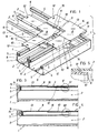
- Figure 1 is an exploded perspective view of two stretches of raceway, each provided with two sub-raceways and of the corresponding angled closing members.
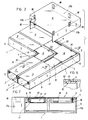
- Figure 2 is an exploded perspective view, similar to Figure 1, of the covering member and of both raceways stretches, with the angled closing members in place.
- Figure 3 is a cross section view on the line III-III of Figure 2.
- Figure 4 is a cross section view on the line IV-IV of Figure 2.
- Figure 5 is a view on a larger scale of the detail in the ring identified as V in Figure 3.
- Figure 6 is a view on a larger scale of the detail in the ring identified as VI in Figure 3.
- Figure 7 is an elevation view, in the direction of the arrow F in Figure 2, of the elbow according to the invention in the active position thereof.
- the elbow according to the invention is for use with raceways for housing electrical cable systems comprising a base section 1 having an internal bottom surface and which is compartmented longitudinally in two or more sub-raceways 2 of the same or different width.
- These raceways also comprise a cover section 3 for each sub-raceway and each cover section 3 is provided with lateral skirts to allow for engagement of both sections 1, 3 by insertion of the said skirts in longitudinal slots 4 provided contiguously to folds 5 capping the external walls 6 and the compartment walls 6' of the base section 1.
- These raceways may assume positions in which the respective bottom surfaces are coplanar and have end cuts 7, such that both end cuts of each raceway may be juxtaposed over the whole extension of both.
- the elbow of the invention comprises, for each sub-raceway 2, a flattened angled closing member 8 which forms a closed conduit with the walls 6, 6' and the internal bottom surfaces of the base section 1 (which are obviously also internal bottom surfaces of the sub-raceways 2), which conduit may be opened for the passage of the electrical cable systems.
- the position in which the elbow is duly engaged for connecting both raceway stretches will be called the active position of the elbow or of the members constituting it.
- These angled closing members 8 are provided with skirts which, in the said active position of the elbow, penetrate in the longitudinal slots 4 of both raceway stretches.
- the elbow also comprises a covering member 9 which, in the said active position, covers from above both angled closing members 8 and is provided with means for engagement with the base sections. Further reference will be made to these engagement means.
- the angled closing member 8 preferably comprises an outstanding centre portion 13 and two channel-like portions 10 disposed as extensions of two contiguous sides of the centre portion 13.
- a step 16 defining a first height, is provided between each channel-like portion 10 and the outstanding centre portion 13.
- the channel-like portions 10 In the said active position, the channel-like portions 10 have the concavity thereof is directed towards the interior of the sub-raceways 2 of the base sections 1. It is contemplated that the channel-like portion 10 be provided, in end portions of the skirts thereof, with barbed teeth 11 which, in the said active position, engage the folds 5, whereby the angled member 8 is removably retained in the base sections 1.
- the angled closing members 8 are also preferably provided with a transverse tab 12 extending from the outer surface thereof and which is situated close to the free edge of the channel-like portion 10.
- the height of the transverse tab 12 is slightly lower than the first height of the step 16 and is of the order of the thickness of the cover section 3.
- the outstanding centre portion 13 forms visors 14 extending laterally and which may bear against the folds 5 of the base sections 1 in the said active position, covering the corresponding portion of the longitudinal slots 4.
- the longer visors have cutaway portions 15 leaving the longitudinal slots 4 uncovered and providing access to the barbed teeth 11.
- the channel-like portion 10, which is in cantilever relationship to the outstanding centre portion 13, is sufficiently resilient for a cover section 3 to be able to deform it, by flexing it, when the cover section 3 is engaged in the base section 1, such that the cover section 3 is mounted on the transverse tab 12, as may be appreciated in Figures 3 and 5, pressing thereagainst.
- the width of the channel-like portion 10 of the angled closing members 8 is of a smaller dimension than the corresponding internal width of the cover sections 3, whereby the channel-like portion may be comprised between the skirts of a cover section 3.
- the covering member 9 is provided with a flat upper surface, the edges of which are straight and each of these edges is disposed at rightangles to the two immediate edges. Two of these edges are short and form a re-entrant angle, i.e. the apex thereof is closer to the centre region of the covering member.
- the short edges are provided with respective skirts 17a and the two edges facing the short edges are also provided with skirts 17b.
- the covering member 9 is also provided with barbed flanges 18, situated in parallel with the skirts 17a, 17b. In the active position of the elbow, they pass through the cutaway portions 15 and penetrate in the longitudinal slots 4, whereby the covering member 9 is removably retained in the base sections 1.
- the transverse tab 12 and the end steps 16 situated between the outstanding centre portion 13 and the channel-like portion 10 may form stops for the cover sections 3. Therefore, since both cover sections 3 of each sub-raceway 2 are the same (provided always that the sub-raceways 2 are of the same width), the angled closing members 8 may be the same both for the sub-raceway situated on the inside of the elbow and for the remaining sub-raceway, which reduces the number of parts required for closing the elbow.
Landscapes
- Engineering & Computer Science (AREA)
- Architecture (AREA)
- Civil Engineering (AREA)
- Structural Engineering (AREA)
- Details Of Indoor Wiring (AREA)
- Thermal Insulation (AREA)
Applications Claiming Priority (2)
| Application Number | Priority Date | Filing Date | Title |
|---|---|---|---|
| ES009800198A ES2147116B1 (es) | 1998-02-03 | 1998-02-03 | Codo plano para la conexion angular de dos tramos de canal para conducciones electricas. |
| ES9800198 | 1998-02-03 |
Publications (3)
| Publication Number | Publication Date |
|---|---|
| EP0933852A1 true EP0933852A1 (fr) | 1999-08-04 |
| EP0933852B1 EP0933852B1 (fr) | 2005-08-24 |
| EP0933852B8 EP0933852B8 (fr) | 2005-10-26 |
Family
ID=8302607
Family Applications (1)
| Application Number | Title | Priority Date | Filing Date |
|---|---|---|---|
| EP99500007A Expired - Lifetime EP0933852B8 (fr) | 1998-02-03 | 1999-01-14 | Elément de connexion angulaire coudé pour deux longueurs de goulotte pour système de cablage électrique |
Country Status (6)
| Country | Link |
|---|---|
| US (1) | US6188024B1 (fr) |
| EP (1) | EP0933852B8 (fr) |
| DE (1) | DE69926823T2 (fr) |
| DK (1) | DK0933852T3 (fr) |
| ES (2) | ES2147116B1 (fr) |
| PT (1) | PT933852E (fr) |
Cited By (5)
| Publication number | Priority date | Publication date | Assignee | Title |
|---|---|---|---|---|
| EP1094582A1 (fr) | 1999-10-22 | 2001-04-25 | Electrix International Limited | Pièce de jonction et couvercle pour conduite |
| EP1241759A1 (fr) * | 2001-03-16 | 2002-09-18 | Tehalit GmbH & Co. KG | Pièce formée pour joindre deux ou plus tronçons de conduite de câbles disposés selon un angle |
| EP1263105A1 (fr) * | 2001-06-01 | 2002-12-04 | Legrand | Dispositif d'angle plat ou de dérivation pour goulottes |
| US6501026B1 (en) | 1999-10-15 | 2002-12-31 | Legrand | Accessory adapted to be attached to a base section of trunking for routing electrical cables |
| EP1351358A1 (fr) * | 2002-04-05 | 2003-10-08 | C & C MARSHALL LIMITED | Assemblage d'angle et de raccord pour un canal fournisseur de services et composant pour celui-ci |
Families Citing this family (37)
| Publication number | Priority date | Publication date | Assignee | Title |
|---|---|---|---|---|
| CA2339604C (fr) * | 2000-03-08 | 2007-09-04 | Hubbell Incorporated | Accessoire de canalisation de cables avec ou sans raccord a embase |
| USD452219S1 (en) | 2000-05-12 | 2001-12-18 | Trim Tex, Inc. | Fiber optic 45 degree corner |
| US6476327B1 (en) * | 2000-06-01 | 2002-11-05 | Panduit Corp. | Split fiber cover and raceway fitting |
| FR2825527B1 (fr) * | 2001-06-01 | 2003-09-05 | Legrand Sa | Accessoire d'angle pour goulotte |
| USD471877S1 (en) | 2001-10-31 | 2003-03-18 | Hellermanntyton Corporation | Raceway fitting |
| US6972367B2 (en) | 2001-10-31 | 2005-12-06 | Hellermanntyton Corporation | Multi-channel raceway |
| US6709186B2 (en) * | 2001-11-16 | 2004-03-23 | Adc Telecommunications, Inc. | Coupler for cable trough |
| CN100550550C (zh) | 2002-03-27 | 2009-10-14 | Adc电信股份有限公司 | 联接器、锁定机构、锁定件及使用联接器和槽构件的方法 |
| US7093997B2 (en) | 2002-03-27 | 2006-08-22 | Adc Telecommunications, Inc. | Coupler for cable trough |
| FR2857791B1 (fr) * | 2003-07-15 | 2005-09-16 | Legrand Sa | Accessoire pour goulotte a verrouillage automatique |
| US7315680B1 (en) * | 2006-06-21 | 2008-01-01 | Adc Telecommunications, Inc. | Cable routing devices with integrated couplers |
| US7459633B2 (en) * | 2006-07-11 | 2008-12-02 | Vantage Point Products Corp. | Wire management system |
| US7896295B2 (en) * | 2007-02-21 | 2011-03-01 | Adc Telecommunications, Inc. | Coupler for cable trough |
| US7463809B2 (en) * | 2007-02-21 | 2008-12-09 | Adc Telecommunications, Inc. | Coupler for cable trough |
| US7584929B2 (en) * | 2007-02-21 | 2009-09-08 | Adc Telecommunications, Inc. | Coupler for cable trough |
| US20080197243A1 (en) * | 2007-02-21 | 2008-08-21 | Adc Telecommunications, Inc. | Coupler for Cable Trough |
| US7493005B2 (en) | 2007-02-21 | 2009-02-17 | Adc Telecommunications, Inc. | Coupler for cable trough |
| US7815152B2 (en) | 2007-02-21 | 2010-10-19 | Adc Telecommunications, Inc. | Coupler for cable trough |
| US7481597B2 (en) * | 2007-02-21 | 2009-01-27 | Adc Telecommunications, Inc. | Coupler for cable trough |
| US7504583B2 (en) * | 2007-02-21 | 2009-03-17 | Adc Telecommunications, Inc. | Coupler for cable trough |
| CA2580058A1 (fr) * | 2007-02-23 | 2008-08-23 | Gordon Nagus | Organisateur et collecteur de tubes de chauffage par rayonnement a partir du plancher |
| US8013259B2 (en) * | 2008-06-11 | 2011-09-06 | Panduit Corp. | Multi position divider clip |
| US8178781B2 (en) * | 2009-01-30 | 2012-05-15 | William Christopher Duffy | Apparatus for protecting cable trays, conduits and/or cables |
| US8757673B2 (en) * | 2009-09-08 | 2014-06-24 | Pandult Corp. | Cover for cable fitting base |
| USD703151S1 (en) * | 2011-02-04 | 2014-04-22 | D-Line (Europe) Limited | Cable conduit |
| US9074788B2 (en) | 2012-01-06 | 2015-07-07 | William Christopher Duffy | Fire-rated modular duct assembly suitable for exhausting flammable or hazardous gases, vapours and other materials |
| JP5704195B2 (ja) * | 2013-07-01 | 2015-04-22 | 株式会社オートネットワーク技術研究所 | プロテクタおよびプロテクタ付きワイヤーハーネス |
| US10024569B2 (en) | 2013-10-10 | 2018-07-17 | William Christopher Duffy | Fire-rated modular duct assembly and improvements therein |
| USD737783S1 (en) * | 2014-08-28 | 2015-09-01 | Bridgeport Fittings, Inc. | Inside corner pull elbow fitting |
| US10790650B2 (en) | 2018-07-09 | 2020-09-29 | Icenine Industries, Llc | Conduit routing system |
| CN108649505B (zh) * | 2018-07-19 | 2024-07-26 | 深圳源通电力工程有限公司 | 一种双通连接头及由其构成的弯头和四通连接头 |
| USD938364S1 (en) * | 2019-06-21 | 2021-12-14 | Switch, Ltd. | Cable distribution bridge |
| USD938365S1 (en) * | 2019-06-21 | 2021-12-14 | Switch, Ltd. | Cable distribution elbow |
| US11777287B1 (en) * | 2022-06-30 | 2023-10-03 | Cablofil, Inc. | Cable tray having cover panels |
| US20240141657A1 (en) * | 2022-10-26 | 2024-05-02 | EZ-Duct, Inc. | Duct Assemblies |
| JP1775553S (ja) * | 2023-01-04 | 2024-07-17 | パイプラインアングルホルダー | |
| US20240429691A1 (en) * | 2023-06-22 | 2024-12-26 | Shoals Technologies Group, Llc | Cable transition systems |
Citations (2)
| Publication number | Priority date | Publication date | Assignee | Title |
|---|---|---|---|---|
| FR2488742A1 (fr) * | 1980-08-12 | 1982-02-19 | Aparellaje Electrico Sa | Coude d'assemblage pour pieces de canalisation de cables electriques |
| GB2174254A (en) * | 1985-04-11 | 1986-10-29 | Ega Ltd | Trunking system component |
Family Cites Families (14)
| Publication number | Priority date | Publication date | Assignee | Title |
|---|---|---|---|---|
| US3003794A (en) * | 1959-03-02 | 1961-10-10 | Hoffman Engineering Corp | Lay-in wireway structure or the like |
| US3697667A (en) * | 1971-06-29 | 1972-10-10 | Firm Tehalit Kunststofoffwerk | Installation channel |
| FR2431209A1 (fr) * | 1978-07-11 | 1980-02-08 | Telemecanique Electrique | Couvre-joint pour plinthes electriques |
| US4398564A (en) * | 1981-09-30 | 1983-08-16 | Federal Cartridge Corporation | Sealed lay-in wireway |
| US4423284A (en) * | 1982-06-04 | 1983-12-27 | Kaplan Steve E | Moulding duct |
| JPH0419938Y2 (fr) * | 1987-12-17 | 1992-05-07 | ||
| FR2642911B1 (fr) * | 1989-02-07 | 1993-11-05 | Legrand | Profile, tel que goulotte, plinthe, moulure ou autre, pour le logement et la protection, en particulier, d'appareillages electriques et des conducteurs necessaires a la desserte de ceux-ci |
| US5024251A (en) * | 1990-01-18 | 1991-06-18 | Square D Company | Lay-in wireway assembly |
| US5134250A (en) * | 1991-04-10 | 1992-07-28 | Panduit Corp. | Wiring duct |
| US5469893A (en) * | 1993-12-21 | 1995-11-28 | Panduit Corp. | Tab and slot fiber optic fitting |
| JP3112383B2 (ja) * | 1994-06-27 | 2000-11-27 | 矢崎総業株式会社 | ロック構造 |
| FR2727578B1 (fr) * | 1994-11-25 | 1997-04-18 | Rehau Ag & Co | Raccord d'angle pour conduits ou canalisations de cable(s) |
| FR2732167B1 (fr) * | 1995-03-21 | 1997-06-06 | Planet Wattohm Sa | Piece de raccordement pour accessoire d'angle pour conduit electrique et accessoire d'angle comportant au moins une telle piece de raccordement |
| FR2741755B1 (fr) * | 1995-11-23 | 1998-02-06 | Legrand Sa | Dispositif de support pour appareillage, en particulier pour appareillage electrique, a rapporter sur un corps de goulotte |
-
1998
- 1998-02-03 ES ES009800198A patent/ES2147116B1/es not_active Expired - Fee Related
-
1999
- 1999-01-14 DK DK99500007T patent/DK0933852T3/da active
- 1999-01-14 EP EP99500007A patent/EP0933852B8/fr not_active Expired - Lifetime
- 1999-01-14 ES ES99500007T patent/ES2244164T3/es not_active Expired - Lifetime
- 1999-01-14 DE DE69926823T patent/DE69926823T2/de not_active Expired - Lifetime
- 1999-01-14 PT PT99500007T patent/PT933852E/pt unknown
- 1999-01-22 US US09/236,286 patent/US6188024B1/en not_active Expired - Fee Related
Patent Citations (2)
| Publication number | Priority date | Publication date | Assignee | Title |
|---|---|---|---|---|
| FR2488742A1 (fr) * | 1980-08-12 | 1982-02-19 | Aparellaje Electrico Sa | Coude d'assemblage pour pieces de canalisation de cables electriques |
| GB2174254A (en) * | 1985-04-11 | 1986-10-29 | Ega Ltd | Trunking system component |
Cited By (10)
| Publication number | Priority date | Publication date | Assignee | Title |
|---|---|---|---|---|
| US6501026B1 (en) | 1999-10-15 | 2002-12-31 | Legrand | Accessory adapted to be attached to a base section of trunking for routing electrical cables |
| EP1094582A1 (fr) | 1999-10-22 | 2001-04-25 | Electrix International Limited | Pièce de jonction et couvercle pour conduite |
| GB2365633A (en) * | 1999-10-22 | 2002-02-20 | Electrix Int Ltd | Cover for a conduit junction piece |
| GB2349513B (en) * | 1999-10-22 | 2002-12-18 | Electrix Int Ltd | A cover plate for a joint between the lids of adjacent pieces of conduit |
| GB2365633B (en) * | 1999-10-22 | 2002-12-18 | Electrix Int Ltd | Cover for a junction piece between adjacent lengths of conduit |
| EP1241759A1 (fr) * | 2001-03-16 | 2002-09-18 | Tehalit GmbH & Co. KG | Pièce formée pour joindre deux ou plus tronçons de conduite de câbles disposés selon un angle |
| DE10112700B4 (de) * | 2001-03-16 | 2004-03-25 | Tehalit Gmbh & Co. Kg | Formteil zum Verbinden von zwei oder mehr Abschnitten eines Kabelkanals |
| EP1263105A1 (fr) * | 2001-06-01 | 2002-12-04 | Legrand | Dispositif d'angle plat ou de dérivation pour goulottes |
| FR2825526A1 (fr) * | 2001-06-01 | 2002-12-06 | Legrand Sa | Dispositif d'angle plat ou de derivation pour goulottes |
| EP1351358A1 (fr) * | 2002-04-05 | 2003-10-08 | C & C MARSHALL LIMITED | Assemblage d'angle et de raccord pour un canal fournisseur de services et composant pour celui-ci |
Also Published As
| Publication number | Publication date |
|---|---|
| ES2147116B1 (es) | 2001-03-16 |
| DE69926823D1 (de) | 2005-09-29 |
| PT933852E (pt) | 2005-11-30 |
| EP0933852B8 (fr) | 2005-10-26 |
| ES2147116A1 (es) | 2000-08-16 |
| US6188024B1 (en) | 2001-02-13 |
| DE69926823T2 (de) | 2006-05-18 |
| DK0933852T3 (da) | 2005-11-14 |
| EP0933852B1 (fr) | 2005-08-24 |
| ES2244164T3 (es) | 2005-12-01 |
Similar Documents
| Publication | Publication Date | Title |
|---|---|---|
| EP0933852B1 (fr) | Elément de connexion angulaire coudé pour deux longueurs de goulotte pour système de cablage électrique | |
| EP0933851B1 (fr) | Dispositif de connexion de deux longueurs de goulotte pour système de cablage electrique | |
| US4589449A (en) | Trunking | |
| US4907767A (en) | Stackable modular duct assemblies | |
| US4952754A (en) | Vapor seal outlet box | |
| US5942724A (en) | Wire containment system for mounting on a wall structure | |
| US6126123A (en) | Living hinge snap lock for wire harness protector | |
| US6265665B1 (en) | Gel-filled casing for an electrical connection and associated method | |
| US6020557A (en) | Conduit connector assembly with angled conduit gripping means | |
| US5688144A (en) | Connection cover | |
| EP0630090B1 (fr) | Dispositif de jonction pour supports de conduites électriques | |
| EP1536533B1 (fr) | Canalisation de cable quart de cercle en plastique extrude | |
| CA2260538A1 (fr) | Clip a ressort d'ensemble de connecteur de conduits avec extremite de retenue de conduit en eventail | |
| EP0035378B1 (fr) | Connecteur électrique | |
| US4229616A (en) | Cable connector cover | |
| GB2314903A (en) | Conduit enclosure system | |
| GB2174254A (en) | Trunking system component | |
| US4960252A (en) | Holder for fastening at least one long round body | |
| US6030237A (en) | Plug connector having a lead exit duct | |
| EP0863343A3 (fr) | Clapet de retenue | |
| JPS5944450A (ja) | 屋根構造用パネル | |
| AU759839B2 (en) | Support with multipart trunking cover portion for equipment to be placed along trunking | |
| EP0198983A2 (fr) | Panneau pour un plafond en treillis | |
| EP0396181B1 (fr) | Système de conduit pour fils électriques et éléments auxiliaires pour un tel système | |
| JP2946461B2 (ja) | レースウェイ接続金具 |
Legal Events
| Date | Code | Title | Description |
|---|---|---|---|
| PUAI | Public reference made under article 153(3) epc to a published international application that has entered the european phase |
Free format text: ORIGINAL CODE: 0009012 |
|
| AK | Designated contracting states |
Kind code of ref document: A1 Designated state(s): BE CH DE DK ES FR GB GR IT LI LU NL PT SE |
|
| AX | Request for extension of the european patent |
Free format text: AL;LT;LV;MK;RO;SI |
|
| 17P | Request for examination filed |
Effective date: 19991004 |
|
| AKX | Designation fees paid |
Free format text: BE CH DE DK ES FR GB GR IT LI LU NL PT SE |
|
| GRAP | Despatch of communication of intention to grant a patent |
Free format text: ORIGINAL CODE: EPIDOSNIGR1 |
|
| GRAS | Grant fee paid |
Free format text: ORIGINAL CODE: EPIDOSNIGR3 |
|
| GRAA | (expected) grant |
Free format text: ORIGINAL CODE: 0009210 |
|
| AK | Designated contracting states |
Kind code of ref document: B1 Designated state(s): BE CH DE DK ES FR GB GR IT LI LU NL PT SE |
|
| REG | Reference to a national code |
Ref country code: GB Ref legal event code: FG4D |
|
| REG | Reference to a national code |
Ref country code: CH Ref legal event code: EP |
|
| REF | Corresponds to: |
Ref document number: 69926823 Country of ref document: DE Date of ref document: 20050929 Kind code of ref document: P |
|
| RAP2 | Party data changed (patent owner data changed or rights of a patent transferred) |
Owner name: UNEX APARELLAJE ELECTRICO S.L. |
|
| REG | Reference to a national code |
Ref country code: GR Ref legal event code: EP Ref document number: 20050402966 Country of ref document: GR |
|
| REG | Reference to a national code |
Ref country code: DK Ref legal event code: T3 |
|
| REG | Reference to a national code |
Ref country code: SE Ref legal event code: TRGR |
|
| REG | Reference to a national code |
Ref country code: CH Ref legal event code: NV Representative=s name: PATENTANWAELTE SCHAAD, BALASS, MENZL & PARTNER AG |
|
| NLT2 | Nl: modifications (of names), taken from the european patent patent bulletin |
Owner name: UNEX APARELLAJE ELECTRICO S.L. Effective date: 20051005 |
|
| REG | Reference to a national code |
Ref country code: ES Ref legal event code: FG2A Ref document number: 2244164 Country of ref document: ES Kind code of ref document: T3 |
|
| ET | Fr: translation filed | ||
| PLBE | No opposition filed within time limit |
Free format text: ORIGINAL CODE: 0009261 |
|
| STAA | Information on the status of an ep patent application or granted ep patent |
Free format text: STATUS: NO OPPOSITION FILED WITHIN TIME LIMIT |
|
| 26N | No opposition filed |
Effective date: 20060526 |
|
| PGFP | Annual fee paid to national office [announced via postgrant information from national office to epo] |
Ref country code: LU Payment date: 20071219 Year of fee payment: 10 |
|
| PGFP | Annual fee paid to national office [announced via postgrant information from national office to epo] |
Ref country code: DK Payment date: 20080115 Year of fee payment: 10 Ref country code: CH Payment date: 20080116 Year of fee payment: 10 |
|
| PGFP | Annual fee paid to national office [announced via postgrant information from national office to epo] |
Ref country code: SE Payment date: 20080104 Year of fee payment: 10 Ref country code: NL Payment date: 20080131 Year of fee payment: 10 Ref country code: GR Payment date: 20071220 Year of fee payment: 10 Ref country code: GB Payment date: 20080109 Year of fee payment: 10 |
|
| PGFP | Annual fee paid to national office [announced via postgrant information from national office to epo] |
Ref country code: BE Payment date: 20080109 Year of fee payment: 10 |
|
| REG | Reference to a national code |
Ref country code: CH Ref legal event code: PL |
|
| EUG | Se: european patent has lapsed | ||
| GBPC | Gb: european patent ceased through non-payment of renewal fee |
Effective date: 20090114 |
|
| NLV4 | Nl: lapsed or anulled due to non-payment of the annual fee |
Effective date: 20090801 |
|
| REG | Reference to a national code |
Ref country code: DK Ref legal event code: EBP |
|
| PG25 | Lapsed in a contracting state [announced via postgrant information from national office to epo] |
Ref country code: LI Free format text: LAPSE BECAUSE OF NON-PAYMENT OF DUE FEES Effective date: 20090131 Ref country code: CH Free format text: LAPSE BECAUSE OF NON-PAYMENT OF DUE FEES Effective date: 20090131 |
|
| PG25 | Lapsed in a contracting state [announced via postgrant information from national office to epo] |
Ref country code: NL Free format text: LAPSE BECAUSE OF NON-PAYMENT OF DUE FEES Effective date: 20090801 Ref country code: GB Free format text: LAPSE BECAUSE OF NON-PAYMENT OF DUE FEES Effective date: 20090114 |
|
| PG25 | Lapsed in a contracting state [announced via postgrant information from national office to epo] |
Ref country code: GR Free format text: LAPSE BECAUSE OF NON-PAYMENT OF DUE FEES Effective date: 20090804 Ref country code: BE Free format text: LAPSE BECAUSE OF NON-PAYMENT OF DUE FEES Effective date: 20090131 |
|
| PG25 | Lapsed in a contracting state [announced via postgrant information from national office to epo] |
Ref country code: DK Free format text: LAPSE BECAUSE OF NON-PAYMENT OF DUE FEES Effective date: 20090731 |
|
| PG25 | Lapsed in a contracting state [announced via postgrant information from national office to epo] |
Ref country code: LU Free format text: LAPSE BECAUSE OF NON-PAYMENT OF DUE FEES Effective date: 20090114 |
|
| PG25 | Lapsed in a contracting state [announced via postgrant information from national office to epo] |
Ref country code: SE Free format text: LAPSE BECAUSE OF NON-PAYMENT OF DUE FEES Effective date: 20090115 |
|
| PGFP | Annual fee paid to national office [announced via postgrant information from national office to epo] |
Ref country code: DE Payment date: 20120111 Year of fee payment: 14 |
|
| PGFP | Annual fee paid to national office [announced via postgrant information from national office to epo] |
Ref country code: IT Payment date: 20120117 Year of fee payment: 14 |
|
| PG25 | Lapsed in a contracting state [announced via postgrant information from national office to epo] |
Ref country code: DE Free format text: LAPSE BECAUSE OF NON-PAYMENT OF DUE FEES Effective date: 20130801 |
|
| REG | Reference to a national code |
Ref country code: DE Ref legal event code: R119 Ref document number: 69926823 Country of ref document: DE Effective date: 20130801 |
|
| PG25 | Lapsed in a contracting state [announced via postgrant information from national office to epo] |
Ref country code: IT Free format text: LAPSE BECAUSE OF NON-PAYMENT OF DUE FEES Effective date: 20130114 |
|
| REG | Reference to a national code |
Ref country code: FR Ref legal event code: PLFP Year of fee payment: 17 |
|
| REG | Reference to a national code |
Ref country code: FR Ref legal event code: PLFP Year of fee payment: 18 |
|
| PGFP | Annual fee paid to national office [announced via postgrant information from national office to epo] |
Ref country code: ES Payment date: 20151230 Year of fee payment: 18 |
|
| PGFP | Annual fee paid to national office [announced via postgrant information from national office to epo] |
Ref country code: FR Payment date: 20160108 Year of fee payment: 18 Ref country code: PT Payment date: 20160105 Year of fee payment: 18 |
|
| REG | Reference to a national code |
Ref country code: FR Ref legal event code: ST Effective date: 20170929 |
|
| PG25 | Lapsed in a contracting state [announced via postgrant information from national office to epo] |
Ref country code: FR Free format text: LAPSE BECAUSE OF NON-PAYMENT OF DUE FEES Effective date: 20170131 |
|
| PG25 | Lapsed in a contracting state [announced via postgrant information from national office to epo] |
Ref country code: PT Free format text: LAPSE BECAUSE OF NON-PAYMENT OF DUE FEES Effective date: 20170714 |
|
| REG | Reference to a national code |
Ref country code: ES Ref legal event code: FD2A Effective date: 20180507 |
|
| PG25 | Lapsed in a contracting state [announced via postgrant information from national office to epo] |
Ref country code: ES Free format text: LAPSE BECAUSE OF NON-PAYMENT OF DUE FEES Effective date: 20170115 |