EP0933879A2 - Emetteur radiofréquence - Google Patents
Emetteur radiofréquence Download PDFInfo
- Publication number
- EP0933879A2 EP0933879A2 EP99101535A EP99101535A EP0933879A2 EP 0933879 A2 EP0933879 A2 EP 0933879A2 EP 99101535 A EP99101535 A EP 99101535A EP 99101535 A EP99101535 A EP 99101535A EP 0933879 A2 EP0933879 A2 EP 0933879A2
- Authority
- EP
- European Patent Office
- Prior art keywords
- amplifiers
- amplifier
- frequency
- power
- frequency transmitter
- Prior art date
- Legal status (The legal status is an assumption and is not a legal conclusion. Google has not performed a legal analysis and makes no representation as to the accuracy of the status listed.)
- Granted
Links
Images

Classifications
-
- H—ELECTRICITY
- H04—ELECTRIC COMMUNICATION TECHNIQUE
- H04B—TRANSMISSION
- H04B1/00—Details of transmission systems, not covered by a single one of groups H04B3/00 - H04B13/00; Details of transmission systems not characterised by the medium used for transmission
- H04B1/02—Transmitters
- H04B1/04—Circuits
-
- H—ELECTRICITY
- H03—ELECTRONIC CIRCUITRY
- H03F—AMPLIFIERS
- H03F3/00—Amplifiers with only discharge tubes or only semiconductor devices as amplifying elements
- H03F3/60—Amplifiers in which coupling networks have distributed constants, e.g. with waveguide resonators
- H03F3/602—Combinations of several amplifiers
-
- H—ELECTRICITY
- H03—ELECTRONIC CIRCUITRY
- H03G—CONTROL OF AMPLIFICATION
- H03G1/00—Details of arrangements for controlling amplification
- H03G1/0005—Circuits characterised by the type of controlling devices operated by a controlling current or voltage signal
- H03G1/0088—Circuits characterised by the type of controlling devices operated by a controlling current or voltage signal using discontinuously variable devices, e.g. switch-operated
Definitions
- the invention relates to a high-frequency transmitter with several amplifiers Preamble of the main claim.
- High-frequency transmitters of this type are known (EP 0 445 139).
- An amplifier broadband linear amplifiers are used, which operate in A mode.
- the The target power of the individual amplifiers is set by means of appropriate Control of the excitation output level. To do this, go from the amplifier outputs the pathogens are used.
- the signal connection device is in the known transmitters designed so that each with the same number of pathogens Only a high-frequency signal is applied to the amplifier, but only when the Number of high-frequency signals exceeds the number of amplifiers, two each High-frequency signals are amplified simultaneously via an amplifier.
- the Amplifiers can be built very easily and inexpensively and the universal for the various applications can be used.
- low-cost regulated ones are used instead of A-linear amplifiers Power amplifier used in AB mode.
- Such AB amplifiers have the advantage that they are not constantly modulated at the operating point and therefore one in idle mode consume much less power than A-amplifiers.
- An A amplifier takes for example, in idle mode a power of 3000 W while an AB amplifier only consumes 400 W of power in idle mode.
- the invention goes into several high-frequency signals to be amplified simultaneously Combination with such more advantageous AB amplifiers the opposite way.
- the Signal connection device is designed and thus has only one Number of connections for exciters that each amplifier never more than one High-frequency signal from an exciter amplifies, if possible, even a lower one Number of high-frequency signals is distributed to a larger number of amplifiers and thereby several amplifiers each in phase with the same high-frequency signal can be controlled.
- Another advantage of the transmitter according to the invention is that via the power-controlled AB amplifiers also the target power of the individual amplifier is controllable without recourse to the exciter. This can also Level losses in the signal connection device due to the setting-dependent, different damping occur, can be compensated in a simple manner. This The advantage is particularly noticeable in combination with the measure, the number choose the amplifier as large as possible than the number of exciters.
- the most varied can be used by the user Operating modes can be selected, there can either be just as many high-frequency signals how existing amplifiers are amplified with different frequencies or only one high-frequency signal with the same frequency and phase on one Large number of individual amplifiers can be divided, in between are the various combinations possible.
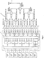
- the invention is based on schematic drawings of a Embodiment explained in more detail.
- the outputs of the amplifiers 1 are via a coupling device 4 with a plurality of 3dB combining circuits C in the form of 3dB couplers in a common output summarized and feed an antenna 5th
- Each individual AB amplifier is constructed according to FIG. 2, it consists of the actual one in AB mode controlled amplifier 1, at the output of a directional coupler 11th is switched on.
- the input signal 12 to be amplified is via a low-distortion voltage-controlled attenuator 13 the input of Amplifier 1 supplied, via the directional coupler 11, the actual output power of Amplifier 1 measured and one together with the desired power Control amplifier 14 supplied.
- About the output of the control amplifier 14 Attenuator 13 controlled.
- the reading of the amplifier 1 is so on entered power setpoint regulated.
- the transmitter can therefore operate in a wide variety of modes be used.
- an adjusting device is in the signal connection device 2 6 provided with which the user can use these different possible modes of operation can adjust.
- the settings are via a serial interface remotely controllable.
- the setting device 6 is connected to a computer 7, which the selected setting in corresponding data telegrams to control the individual Exciter inputs and amplifiers implemented. This is done via a control circuit 8, which, for example, the required powers for the control amplifier 14 of the individual amplifier can be set.
- the signal connection device 2 are in addition, four additional power splitters 9 are provided, which make it possible to use one high-frequency signal supplied to them on two, three or four outputs in phase split up.
- the inputs of these power splitters can be shown schematically indicated connection device 20 to be connected to each of the exciters 3 two to four divided outputs via a schematically indicated Connection device 21 with the respectively selected amplifiers 1.
- a great advantage of the arrangement according to the invention is that Signal connection device can also be used less than eight amplifiers can, so that, for example, without interrupting the transmitter operation, one or more currently unused amplifiers can be removed and serviced or repaired.
- Another advantage is that the individual exciters each have a constant output level have and are not regulated themselves, because the power setting of the amplifier in the Signal connection device is carried out via the control circuit of the amplifier.
Landscapes
- Engineering & Computer Science (AREA)
- Power Engineering (AREA)
- Computer Networks & Wireless Communication (AREA)
- Signal Processing (AREA)
- Amplifiers (AREA)
- Transmitters (AREA)
Applications Claiming Priority (2)
| Application Number | Priority Date | Filing Date | Title |
|---|---|---|---|
| DE19804199 | 1998-02-03 | ||
| DE19804199A DE19804199A1 (de) | 1998-02-03 | 1998-02-03 | Hochfrequenz-Sender |
Publications (3)
| Publication Number | Publication Date |
|---|---|
| EP0933879A2 true EP0933879A2 (fr) | 1999-08-04 |
| EP0933879A3 EP0933879A3 (fr) | 2000-06-07 |
| EP0933879B1 EP0933879B1 (fr) | 2002-05-08 |
Family
ID=7856505
Family Applications (1)
| Application Number | Title | Priority Date | Filing Date |
|---|---|---|---|
| EP99101535A Expired - Lifetime EP0933879B1 (fr) | 1998-02-03 | 1999-01-29 | Emetteur radiofréquence |
Country Status (2)
| Country | Link |
|---|---|
| EP (1) | EP0933879B1 (fr) |
| DE (2) | DE19804199A1 (fr) |
Family Cites Families (6)
| Publication number | Priority date | Publication date | Assignee | Title |
|---|---|---|---|---|
| FI80815C (fi) * | 1988-09-13 | 1990-07-10 | Nokia Mobira Oy | Linearisation av en foerstaerkning i en rf-foerstaerkare. |
| US5163181A (en) * | 1988-10-21 | 1992-11-10 | Harris Corporation | Multiple rf signal amplification method and apparatus |
| TW198152B (fr) * | 1990-10-18 | 1993-01-11 | Hitachi Seisakusyo Kk | |
| DE4226806A1 (de) * | 1992-08-13 | 1994-02-17 | Telefunken Sendertechnik | Linearisierungsverfahren für eine HF-Verstärkerendstufe |
| US5659891A (en) * | 1995-06-07 | 1997-08-19 | Mobile Telecommunication Technologies | Multicarrier techniques in bandlimited channels |
| SE9601619L (sv) * | 1996-04-29 | 1997-10-30 | Radio Design Innovation Tj Ab | Anordning med sändarkombinerare |
-
1998
- 1998-02-03 DE DE19804199A patent/DE19804199A1/de not_active Withdrawn
-
1999
- 1999-01-29 EP EP99101535A patent/EP0933879B1/fr not_active Expired - Lifetime
- 1999-01-29 DE DE59901372T patent/DE59901372D1/de not_active Expired - Lifetime
Also Published As
| Publication number | Publication date |
|---|---|
| EP0933879A3 (fr) | 2000-06-07 |
| EP0933879B1 (fr) | 2002-05-08 |
| DE19804199A1 (de) | 1999-08-05 |
| DE59901372D1 (de) | 2002-06-13 |
Similar Documents
| Publication | Publication Date | Title |
|---|---|---|
| DE3911373C2 (de) | Phasengesteuertes Radargerät mit Selbstüberwachung/Selbstabgleich und auswechselbare einstellbare Sende/Empfangs-Baueinheit | |
| DE69917212T2 (de) | Leistungsverstärkervorrichtung und verfahren dafür | |
| DE2214947A1 (de) | Schalteinrichtuag | |
| DE2519845C3 (de) | Schaltungsanordnung zur Zusammenführung von Hochfrequenzleistungsanteilen | |
| DE69833143T2 (de) | Senderverstärkungsregler | |
| DE102012223662B4 (de) | Verfahren zur Erzeugung einer Hochfrequenzleistung und Leistungsversorgungssystem mit einem Leistungswandler zur Versorgung einer Last mit Leistung | |
| DE69920838T2 (de) | Lineare Verstärkeranordnung | |
| DE2147167A1 (de) | Vorrichtung zur Verringerung der Zwischenmodulation | |
| EP0933879B1 (fr) | Emetteur radiofréquence | |
| DE69421684T2 (de) | Verfahren und vorrichtung zum steuern eines hochfrequenz-leistungsverstärkers | |
| DE10148441C1 (de) | Dynamikkompressor für ein zu komprimierendes Analogsignal | |
| EP1326131A1 (fr) | Ligne optique à retard variable et procédé permettant l'utilisation de la ligne optique à retard variable | |
| DE102005058039A1 (de) | Schaltungsanordnung und Verfahren zur Verstärkung eines elektrischen Eingangssignals | |
| DE102006008725B4 (de) | Mehrkanalverstärker mit reduzierter Gesamtleistungsabgabe und Schaltungsanordnung mit einem derartigen Mehrkanalverstärker | |
| DE10133509C2 (de) | Übertragung von Daten über das Stromversorgungsnetz | |
| EP0316611B1 (fr) | Installation de transmission radio THF comportant au moins deux transmetteurs à fréquence différente | |
| EP0247615B1 (fr) | Emetteur pour ondes courtes électro-magnétiques | |
| DE102005044620A1 (de) | Front-End-Modul für drahtlose Kommunikationsmittel | |
| EP0357876A2 (fr) | Procédé pour l'optimisation de l'accord d'un émetteur et montage pour la réalisation du procédé | |
| DE19706334A1 (de) | Logarithmische Umformschaltung | |
| DE10009596A1 (de) | Vorrichtung zur Linearisierung eines Hochfrequenz-Verstärkers | |
| DE4236473C1 (de) | Kompensationsanordnung für einen Fernseh-HF-Verstärker | |
| EP0277501A2 (fr) | Montage en pont comportant des résistances de distribution de charge | |
| DE19536233B4 (de) | Verfahren zum Regeln des Pegels des Ausgangssignals eines bereichsselektiven Hochfrequenz-Verstärkers für Mehrkanalsysteme und bereichsselektiver Hcohfrequenz-Verstärker mit Pegelregelschaltung | |
| DE1466172C (de) | Verfahren zur Einstellung der frequenzabhängigen Verstärkungscharakteristik eines Verstärkers |
Legal Events
| Date | Code | Title | Description |
|---|---|---|---|
| PUAI | Public reference made under article 153(3) epc to a published international application that has entered the european phase |
Free format text: ORIGINAL CODE: 0009012 |
|
| AK | Designated contracting states |
Kind code of ref document: A2 Designated state(s): DE FR GB IT NL |
|
| AX | Request for extension of the european patent |
Free format text: AL;LT;LV;MK;RO;SI |
|
| PUAL | Search report despatched |
Free format text: ORIGINAL CODE: 0009013 |
|
| AK | Designated contracting states |
Kind code of ref document: A3 Designated state(s): AT BE CH CY DE DK ES FI FR GB GR IE IT LI LU MC NL PT SE |
|
| AX | Request for extension of the european patent |
Free format text: AL;LT;LV;MK;RO;SI |
|
| RIC1 | Information provided on ipc code assigned before grant |
Free format text: 7H 04B 1/04 A, 7H 03F 3/60 B, 7H 03G 1/00 B |
|
| 17P | Request for examination filed |
Effective date: 20000530 |
|
| 17Q | First examination report despatched |
Effective date: 20001030 |
|
| AKX | Designation fees paid |
Free format text: DE FR GB IT NL |
|
| GRAG | Despatch of communication of intention to grant |
Free format text: ORIGINAL CODE: EPIDOS AGRA |
|
| GRAG | Despatch of communication of intention to grant |
Free format text: ORIGINAL CODE: EPIDOS AGRA |
|
| GRAH | Despatch of communication of intention to grant a patent |
Free format text: ORIGINAL CODE: EPIDOS IGRA |
|
| GRAH | Despatch of communication of intention to grant a patent |
Free format text: ORIGINAL CODE: EPIDOS IGRA |
|
| REG | Reference to a national code |
Ref country code: GB Ref legal event code: IF02 |
|
| GRAA | (expected) grant |
Free format text: ORIGINAL CODE: 0009210 |
|
| AK | Designated contracting states |
Kind code of ref document: B1 Designated state(s): DE FR GB IT NL |
|
| GBT | Gb: translation of ep patent filed (gb section 77(6)(a)/1977) |
Effective date: 20020509 |
|
| REF | Corresponds to: |
Ref document number: 59901372 Country of ref document: DE Date of ref document: 20020613 |
|
| ET | Fr: translation filed | ||
| PLBE | No opposition filed within time limit |
Free format text: ORIGINAL CODE: 0009261 |
|
| STAA | Information on the status of an ep patent application or granted ep patent |
Free format text: STATUS: NO OPPOSITION FILED WITHIN TIME LIMIT |
|
| 26N | No opposition filed |
Effective date: 20030211 |
|
| REG | Reference to a national code |
Ref country code: FR Ref legal event code: PLFP Year of fee payment: 17 |
|
| REG | Reference to a national code |
Ref country code: FR Ref legal event code: PLFP Year of fee payment: 18 |
|
| REG | Reference to a national code |
Ref country code: FR Ref legal event code: PLFP Year of fee payment: 19 |
|
| REG | Reference to a national code |
Ref country code: FR Ref legal event code: PLFP Year of fee payment: 20 |
|
| PGFP | Annual fee paid to national office [announced via postgrant information from national office to epo] |
Ref country code: NL Payment date: 20180124 Year of fee payment: 20 |
|
| PGFP | Annual fee paid to national office [announced via postgrant information from national office to epo] |
Ref country code: GB Payment date: 20180125 Year of fee payment: 20 Ref country code: DE Payment date: 20180130 Year of fee payment: 20 |
|
| PGFP | Annual fee paid to national office [announced via postgrant information from national office to epo] |
Ref country code: FR Payment date: 20180124 Year of fee payment: 20 Ref country code: IT Payment date: 20180126 Year of fee payment: 20 |
|
| REG | Reference to a national code |
Ref country code: DE Ref legal event code: R071 Ref document number: 59901372 Country of ref document: DE |
|
| REG | Reference to a national code |
Ref country code: NL Ref legal event code: MK Effective date: 20190128 |
|
| REG | Reference to a national code |
Ref country code: GB Ref legal event code: PE20 Expiry date: 20190128 |
|
| PG25 | Lapsed in a contracting state [announced via postgrant information from national office to epo] |
Ref country code: GB Free format text: LAPSE BECAUSE OF EXPIRATION OF PROTECTION Effective date: 20190128 |