EP0933884A2 - Sendeleistungsanpassung insbesondere bei der drahtlosen In-House-Kommunikation - Google Patents
Sendeleistungsanpassung insbesondere bei der drahtlosen In-House-Kommunikation Download PDFInfo
- Publication number
- EP0933884A2 EP0933884A2 EP99101174A EP99101174A EP0933884A2 EP 0933884 A2 EP0933884 A2 EP 0933884A2 EP 99101174 A EP99101174 A EP 99101174A EP 99101174 A EP99101174 A EP 99101174A EP 0933884 A2 EP0933884 A2 EP 0933884A2
- Authority
- EP
- European Patent Office
- Prior art keywords
- communication device
- test signal
- transmission power
- communication
- transmission
- Prior art date
- Legal status (The legal status is an assumption and is not a legal conclusion. Google has not performed a legal analysis and makes no representation as to the accuracy of the status listed.)
- Granted
Links
Images


Classifications
-
- H—ELECTRICITY
- H04—ELECTRIC COMMUNICATION TECHNIQUE
- H04W—WIRELESS COMMUNICATION NETWORKS
- H04W52/00—Power management, e.g. Transmission Power Control [TPC] or power classes
- H04W52/04—Transmission power control [TPC]
- H04W52/38—TPC being performed in particular situations
- H04W52/50—TPC being performed in particular situations at the moment of starting communication in a multiple access environment
-
- H—ELECTRICITY
- H04—ELECTRIC COMMUNICATION TECHNIQUE
- H04B—TRANSMISSION
- H04B17/00—Monitoring; Testing
- H04B17/0082—Monitoring; Testing using service channels; using auxiliary channels
- H04B17/0085—Monitoring; Testing using service channels; using auxiliary channels using test signal generators
Definitions
- the invention relates to a method for adjusting the transmission power Communication devices, in particular in consumer electronics devices.
- Such communication devices come, for example, from a so-called "IN-House" network in use.
- the IN-House network is used for the transmission of Information to various communication devices within a house, such as TV, heating, room surveillance, and between this.
- the invention has for its object a method for Specify transmit power adjustment, which is a simple reduction enables the transmission line.
- This task is accomplished by a procedure for adjusting the transmission power Communication devices, in particular in consumer electronics devices solved in which a first test signal from a first communication device is emitted, this test signal from a second communication device is received and sent back again.
- the first communication device the one received and returned by the second communication device Test signal examined for agreement with the original. From the degree of Agreement becomes a controlled variable for regulating the transmission power of the first communication device is derived.
- the invention is based on the finding that it is wireless, for example coupled communication devices is often not required that the communication devices with a constant, i.e. with a relatively high, Send out power signals.
- There is one application for example in that additional speakers wirelessly coupled to a television in are arranged in close proximity to the television set. In this case, it is complete sufficient if the transmission power in the transmission of television sound signals is reduced to the bare minimum.
- the first communication device for example, from the television, when the Additional speakers sent a test signal. This test signal is from second communication device received and sent again. in the Television, i.e. There then takes place in the first communication device Evaluation of the received test signal, the transmission power then in Predefinable steps can be reduced until the desired Signal quality is just reached.
- the advantage of the procedure is there in particular in that the transmission power of the communication devices on the Necessary is reduced, which on the one hand reduces energy consumption and on the other others burdened the user with a minimum of RF energy and thus too leads to a reduction in the phenomenon of "electrosmog".
- Housing units When operating several communication devices within a house or in neighboring ones Housing units will also disrupt the respective Communication devices avoided or at least reduced.
- a disturbance in the useful data transmission by the test signal can easily be Way avoided in that the transmission power adjustment at the beginning establishing a connection before the start of a transmission of user data or in parallel between the first and the second communication device he follows.
- the use of the method for adapting the transmission power is particularly in the Suitable cases when the first communication device Signal processing device for processing analog and / or digital Sound and / or image signals, in particular from radio, television and / or Has telephone signals and the second communication device Subscriber device available from the signal processing device standing services.
- Particularly suitable applications of the method are that the first and the second communication device via a wireless or a wired bidirectional connection can be coupled.
- the Transmission of the test signal from the first communication device via a first Transmission medium in particular a wireless transmission medium take place during the retransmission of the test signal from the second Communication device to the first communication device via a second Transmission medium, in particular a wired transmission medium can be done.
- the first communication device 100 sends Test signal 102 received by a second communication device 101 becomes.
- the second communication device 101 becomes that in the received manner Test signal 103, which is the received test signal 102, remains the same as that Test signal 102 was received to the first communication device 100 sent back.
- the first Communication device 100 the received test signal 103 for agreement with the original, i.e. checked with the test signal 102 and from the degree of Agreement made an adjustment of the transmission power.
- the Transmission power of the communication device 100 is reduced until the Degree of agreement reached an adjustable limit.
- 101 can adapt the transmission power take place continuously in parallel with the transmission of useful signals. With stationary operated communication devices 100, 101, it is usually sufficient if the setting of a transmission power when the Communication devices 100, 101 is performed.
- FIG. 2 shows a block diagram with a schematic diagram for generating a Transmitting power control signal 109.
- the parts of the Block diagrams are shown, for example, in FIG. 1 Communication device 100 integrated. This is shown in detail in FIG. 2 Block diagram of a test pattern generator 104 which sends a test signal 102 to a Transmitter 105 and forwarded to a limit comparator 108. Of the Limit comparator 108 is designed as a comparator. The result of Comparator is fed to an evaluation unit, which the quality of the received test signal 103 evaluated to the original test signal 102.
- the Transmitting device 105 is connected to a transmitting / receiving antenna 106.
- a receiving device 107 is provided, which also with the transceiver antenna 106 is coupled.
- the receiving device 107 receives an from a second communication device (cf. FIG. 1) Communication device 100 returned test signal 103, which the Comparator 108 is supplied. At the exit of the comparison device 108, a controlled variable 109 is formed which is used to adjust the transmission power of the Transmitter 105 serves. An im Communication device 100 available for useful signal transmission anyway Useful signal transmitter can be used. The same applies to the receiving device 107.
- Test signal generator 104 may be one Digital signal or, depending on the application, also an analog test signal produce.
- the test signal 102 generated by the test signal generator 104 is, if necessary, in Connection with an identification signal for your own and / or for identification a called partner, i.e. to a second communication device, with which is to be used to establish a connection. From this remote site, i.e. from the second communication device, this test signal is received and again, possibly also with a corresponding identifier of the first Communication device from which the test signal 102 was sent sent back.
- the received test signal is in the first communication device 103 for agreement with the test signal 102 originally sent checked.
- the comparison device 108 in which a limit value or a criterion is stored which is the minimum of the required Quality of reception.
- the comparison device 108 is designed in such a way that first a target-actual comparison is carried out, then a comparison of the deviation with made a predetermined limit.
- the test signal 102 and the test signal 103 correspond with the help of the controlled variable 109 supplied by the comparison device 108 Adjusted transmission power of the transmitter 105.
- the inventive method is achieved in that poorer performance or more distant modems or transmitters not by stronger or in modems or transmitters in the immediate vicinity "drown out” or “run over”. It also prevents high Transmission level through the input sensitivity of the receiver 107 For example, respond to an automatic gain control is reduced, which in turn when receiving signal with a weaker level would be disadvantageous.
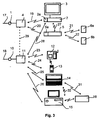
- Fig. 3 shows an embodiment of a communication system, which a Large number of communication devices 2, 3, 4, 5, 6a, 6b, 11, 12, 13, 14, 15, 16 having.
- the communication system shown in FIG. 3 has a first one Signal source 1, which is provided for the distribution of television signals 17, received via cable, satellite or terrestrial.
- the signals 17 of the Signal source 1 are fed to a signal processing device 4 which the Distribution of the signals 17 to communication devices 2, 3, 5 is used.
- the Communication devices 2, 3, 5 are in that shown in Fig. 3 Embodiments of a TV receiver 2 with a receiving device 2a Screen 3, and a radio receiver 5 with a receiving part 5a.
- the transmission of the signals 17 between the signal processing device 4 and the television or radio receiver 2, 5 takes place wirelessly via Radio interfaces 19, 20.
- the signals received by the radio receiver 5 can via further radio interfaces 21, 22, for example as Infrared interfaces are formed, distributed to speakers 6a, 6b.
- the 3 also has a second communication system Signal source 10 for receiving telephone signals 18.
- the telephone signals 18 are fed to a second signal processing device 11, which via Radio interfaces 23 to 26 can be connected to terminals 12 to 16.
- a second signal processing device 11 which via Radio interfaces 23 to 26 can be connected to terminals 12 to 16.
- Communication terminals are the one shown in Fig. 3 Embodiment a telephone set 12, a cordless telephone set 13 portable personal computer 14, and a stationary personal computer 15 with Printer 16 which can be connected via an interface 31 is provided.
- a Connection between stationary personal computer 15 and portable Personal computer 14 is possible via a further interface 32. That in Fig.
- 3 communication system shown also has a dashed line drawn connection possibility between the Signal conditioning devices 4, 11, whereby a connection of the different signal sources 4, 11 is possible. It is also about one Radio interface 28 also a coupling of the TV receiving device 2 to the second signal source 10 is provided.
- the communication system shown in Fig. 3 is based on a decentralized Structure of signal sources 1, 10, i.e. the signal sources 1, 10 and corresponding signal processing devices 4, 11 are with the respective Communication terminals 2, 3, 5 to 12 to 15 directly via the wireless in-house connection connected.
- Such a decentralized structure of the communication system has the advantage that all services of the signal sources 1, 10 at the respective location at which they are used Are available, can be distributed directly without a central Summary must be made into a data stream. This can be a additional cabling to an otherwise necessary central station be avoided.
- the delivery of unnecessary transmission power from the Communication terminals is reduced to a minimum in that the 1, 2, 4, methods used for transmitting power adaptation are provided is. This will send out the data via the radio interfaces Transmission power reduced to a minimum and thus interference from the different communication devices with each other, as well as for the user of the Communication terminals, reduced to a minimum.
- Signal source 1 is, for example, a data source that provides television signals that are supplied to signal processing device 4 via connecting line 17.
- the signal conditioning device 4 is used to decode the television signals supplied by the signal source 1, and to radiate the correspondingly processed television signals to the respective terminals 2, 3, 5.
- the wireless connection of the terminals 2, 3, 5 to the signal conditioning device 4 thus eliminates, for example, within an additional wiring effort for a residential unit.
- the telephone signals supplied by the signal source 10 via the connecting line 18 are transmitted from the second signal processing device 11 to the communication terminals 12 to 15 which can be coupled to the latter.
- the communication terminals such as the personal computer 15, to be connected to a plurality of signal sources 1, 10.
- the communication system shown in FIG. 3 thus has communication terminals which do not access any service, as is the case, for example, with the loudspeakers 6a, 6b shown in FIG. 3 and the printer 16.
- communication terminals are also provided which use only a single service; as is the case for example with the telephone 12, 13.
- the communication system shown in FIG. 1 results in a flexible adaptation to the corresponding signal sources 1, 10.
- the signal processing devices 4, 11 and the communication terminals 2 have direct processing so that the different terminals can have direct access to the different signal sources 1, 10 , 3, 5, 12 to 15 corresponding modems that are used for addressing and logging in and out.
- the transmission power required in each case is only set permanently when these devices are put into operation for the first time, while the transmission power adjustment in the case of communication devices 14, 13 operated in mobile use each time a connection is established and, if appropriate, also continuously the transfer takes place.
- a transmission power adjustment can also be carried out in the event of a change, for example as a result of a newly added communication device.
- a channel access method such as CDMA, DTMA or FDMA or a combination of these methods is used as the transmission method, for example.
- the radio interface 28 between the TV receiving device 2 and the signal processing device 11 for the second signal source 10 makes it possible, for example, to receive fax messages or to access communication services such as the Internet.
- Fig. 4 shows a second embodiment for transmitting a transmission power control signal in two communication devices. The reference symbols already introduced in connection with FIG. 1 are used.
- a test signal 102 is transmitted by a first communication device 100 via an air interface 110. This test signal 102 is received by a second communication device 101.
- a line-bound transmission connection 111 is provided as the “back channel” for transmitting the test signal 103 received by the second communication device to the first communication device 100.
- This is, for example, the power supply network, the antenna network or the telephone network to which both the first communication device 100 and the second communication device 101 are connected.
- the advantage of the method shown in Fig. 4 is that the second Communication device 101 no special transmission device for delivering a wireless transmission signal needed. Rather, it can be based on an existing one Connection line 111 can be used to transmit the received test signal, d. H. of the test signal 103 is used.
- Fig. 5 shows an embodiment of a communication network with a Head station 200 for distributing audio and / or video signals.
- the headend 200 has a receiving device 204, which receives signals Satellite antenna 206 are supplied.
- a control modem 205 is provided, which the distribution of the video and / or Controls audio signals to communication devices 201, 202, 203, 207.
- the basic function of such a head-end station 200 is primarily in the distribution of the television and Audio signals.
- that arranged in the head station 200 serves Modem 205 to control or to adapt the required Transmit power.
- the modem 205 sends the head station 200 for example to the modem of the communication device 201 that is specifically addressable, for example by means of an identification code Test signal.
- This test signal is from the communication device, for example a television 201 or from one with this television 201 coupled modem received and back to the headend 200 sent back. From the degree of correspondence between the sent and again the received test signal becomes a controlled variable for controlling the Transmission power of the modem 205 of the head-end station 200 to supply the modem of the communication device 201.
- the facility is that, for example, an existing cable system may be under Using the power supply network also for controlling the Transmission power adjustment can be used with.
- An adaptation of the transmission power required in each case has the further consequence that, in contrast to uniformly high transmission power interference from also in the Communication network contained further communication devices avoided or be reduced to a minimum.
- the invention thus relates to a method for Adjustment of the transmission power, particularly in the case of communication devices for in-house communication.
- Such communication devices are, for example TV playback devices with reception facilities or Storage devices are coupled.
- To adapt each individually required transmission powers it is proposed that in particular at the beginning a transmission between two communication devices from a connection producing the first communication device, a test pattern is sent, the the remote site, i.e. of the second receiving the test pattern Communication device is sent back. From the degree of agreement from the transmitted and received test signal is derived with which Transmission power the communication devices are operated. This will on the one hand, the energy consumption of the communication devices on each required dimension reduced. In addition, interferences become more neighboring Communication devices minimized. The reduced transmission powers lead also to reduce the so-called electrosmog.
Landscapes
- Engineering & Computer Science (AREA)
- Computer Networks & Wireless Communication (AREA)
- Signal Processing (AREA)
- Physics & Mathematics (AREA)
- Electromagnetism (AREA)
- Mobile Radio Communication Systems (AREA)
- Monitoring And Testing Of Transmission In General (AREA)
- Compositions Of Macromolecular Compounds (AREA)
- Transmitters (AREA)
- Radio Relay Systems (AREA)
Abstract
Description
- Fig. 1
- ein erstes Ausführungsbeispiel zur Übertragung eines Sendeleitungsregelsignals mit zwei Kommunikationsgeräten,
- Fig. 2
- ein Blockschaltbild mit einer Prinzipdarstellung der Erzeugung eines Sendeleitungsregelsignals,
- Fig. 3
- ein Ausführungsbeispiel eines Kommunikationsnetzes,
- Fig. 4
- ein zweites Ausführungsbeispiel zur Übertragung eines Sendeleitungsregelsignals mit zwei Kommunikationsgeräten und
- Fig. 5
- ein weiteres Ausführungsbeispiel eines Kommunikationsnetzes mit einer Kopfstation zur Verteilung von Medien und/oder Videosignalen.
Fig. 4 zeigt ein zweites Ausführungsbeispiel zur Übertragung eines Sendeleistungsregelsignals bei zwei Kommunikationsgeräten. Dabei werden die bereits im Zusammenhang mit Fig.1 eingeführten Bezugszeichen verwendet. Bei dem in Fig. 4 dargestellten Ausführungsbeispiel wird von einem ersten Kommunikationsgerät 100 über eine Luftschnittstelle 110 ein Testsignal 102 ausgesendet. Dieses Testsignal 102 wird von einem zweiten Kommunikationsgerät 101 empfangen. Als ''Rückkanal'' zur Übertragung des vom zweiten Kommunikationsgerät empfangenen Testsignals 103 an das erste Kommunikationsgerät 100 ist eine leitungsgebundene Übertragungsverbindung 111 vorgesehen. Dabei handelt es sich beispielsweise um das Stromversorgungsnetz, das Antennennetz oder das Telefonnetz, an das sowohl das erste Kommunikationsgerät 100, als auch das zweite Kommunikationsgerät 101 angeschlossen sind.
Claims (10)
- Verfahren zur Sendeleistungsanpassung bei Kommunikationsgeräten (100, 101) insbesondere bei Geräten der Unterhaltungselektronik, bei dem von einem ersten Kommunikationsgerät (100) ein Testsignal (102) ausgesendet wird und das Testsignal (102) von einem zweiten Kommunikationsgerät (101) empfangen und als Testsignal (103) wieder zurückgesendet wird, wobei im ersten Kommunikationsgerät (100) das vom zweiten Kommunikationsgerät (101) gesendete Testsignal (103) auf Übereinstimmung mit dem Original untersucht wird und aus dem Grad der Übereinstimmung eine Regelgröße (109) zur Regelung der Sendeleistung des ersten Kommunikationsgerätes (100) abgeleitet wird.
- Verfahren nach Anspruch 1,
dadurch gekennzeichnet,
daß die Sendeleistung solange verringert wird, bis der Grad der Übereinstimmung zwischen dem gesendeten Testsignal (102) und dem empfangenen Testsignal (103) einen vorgebbaren Grenzwert nicht unterschreitet. - Verfahren nach einem der Ansprüche 1 oder 2,
dadurch gekennzeichnet,
daß die Sendeleistungsanpassung einmalig bei Erstinbetriebnahme einer aus stationären Kommunikationsgeräten (100, 101) bestehende Kommunikationsgerätekonfiguration erfolgt. - Verfahren nach einem der Ansprüche 1 bis 3,
dadurch gekennzeichnet,
daß die Sendeleistungsanpassung bei einem zusätzlich hinzukommenden Kommunikationsgerät und/oder in vorgebbaren Zeitabständen erfolgt. - Verfahren nach einem der Ansprüche 1 bis 4,
dadurch gekennzeichnet,
daß die aktuell erforderliche Sendeleistung kontinuierlich in Abhängigkeit des jeweils ermittelten Grades der Übereinstimmung des gesendeten Testsignals (102) und des empfangenen Testsignals (103) ermittelt und eingestellt wird. - Verfahren nach einem der Ansprüche 1 bis 5,
dadurch gekennzeichnet,
daß die Sendeleistungsanpassung zu Beginn einer Verbindungsaufnahme vor Beginn einer Übertragung von Nutzdaten oder parallel hierzu zwischen dem ersten (100) und dem zweiten Kommunikationsgerät (101) erfolgt. - Verfahren nach einem der Ansprüche 1 bis 6,
dadurch gekennzeichnet,
daß das erste Kommunikationsgerät (100) eine Signalaufbereitungseinrichtung (4, 11) zur Aufbereitung von analogen und/oder digitalen Ton- und/oder Bildsignalen, insbesondere von Rundfunk-, Fernseh- und/oder Telefonsignalen aufweist und daß das zweite Kommunikationsgerät (101) ein Teilnehmergerät an von der Signalaufbereitungseinrichtung (4, 11) zur Verfügung stehenden Dienste ist. - Verfahren nach einem der Ansprüche 1 bis 7,
dadurch gekennzeichnet,
daß das erste Kommunikationsgerät (100) und das zweite Kommunikationsgerät (101) über eine drahtlose oder eine drahtgebundene bidirektionale Verbindung miteinander koppelbar sind. - Verfahren nach einem der Ansprüche 1 bis 8,
dadurch gekennzeichnet,
daß die Übertragung des Testsignals (102) vom ersten Kommunikationsgerät (100) über ein erstes Übertragungsmedium, insbesondere ein drahtloses Übertragungsmedium (110) erfolgt und daß die Rückübertragung des Testsignals (103) vom zweiten Kommunikationsgerät (101) zum ersten Kommunikationsgerät (100) über ein zweites Übertragungsmedium (111), insbesondere ein drahtgebundenes Übertragungsmedium erfolgt. - Kommunikationsgerät (100, 101) mit Mitteln zur Durchführung des Verfahrens nach einem der Ansprüche 1 bis 9.
Applications Claiming Priority (2)
| Application Number | Priority Date | Filing Date | Title |
|---|---|---|---|
| DE19803849A DE19803849A1 (de) | 1998-01-31 | 1998-01-31 | Sendeleistungsanpassung insbesondere bei der drahtlosen In-House-Kommunikation |
| DE19803849 | 1998-01-31 |
Publications (3)
| Publication Number | Publication Date |
|---|---|
| EP0933884A2 true EP0933884A2 (de) | 1999-08-04 |
| EP0933884A3 EP0933884A3 (de) | 2001-08-16 |
| EP0933884B1 EP0933884B1 (de) | 2006-08-16 |
Family
ID=7856289
Family Applications (1)
| Application Number | Title | Priority Date | Filing Date |
|---|---|---|---|
| EP99101174A Expired - Lifetime EP0933884B1 (de) | 1998-01-31 | 1999-01-22 | Sendeleistungsanpassung insbesondere bei der drahtlosen In-House-Kommunikation |
Country Status (4)
| Country | Link |
|---|---|
| EP (1) | EP0933884B1 (de) |
| AT (1) | ATE336831T1 (de) |
| DE (2) | DE19803849A1 (de) |
| ES (1) | ES2272019T3 (de) |
Families Citing this family (3)
| Publication number | Priority date | Publication date | Assignee | Title |
|---|---|---|---|---|
| DE19949918B4 (de) * | 1999-10-16 | 2005-09-15 | Grundig Multimedia B.V. | Drahtlose digitale Audioübertragung im Heimbereich |
| DE102007049288A1 (de) * | 2007-10-12 | 2009-04-30 | Dernedde, Niels | Biokompatibles, drahtloses Fernwirkverfahren |
| DE102007053330B4 (de) * | 2007-11-08 | 2019-01-31 | Blum-Novotest Gmbh | Verfahren zur Regelung der Sendeleistung einer Sende-/Empfangsvorrichtung in einem Positionsmesssystem für eine Maschine und Sende-/Empfangsvorrichtung |
Family Cites Families (5)
| Publication number | Priority date | Publication date | Assignee | Title |
|---|---|---|---|---|
| EP0079612B1 (de) * | 1981-11-16 | 1986-10-08 | Nec Corporation | Sendeleistungsregelsystem einer Bodenstation |
| JPH04144317A (ja) * | 1990-10-04 | 1992-05-18 | Nec Corp | 衛星通信地球局の送信電力制御方式 |
| US5220678A (en) * | 1991-08-12 | 1993-06-15 | Motorola, Inc. | Method and apparatus for adjusting the power of a transmitter |
| DE4242705C2 (de) * | 1992-12-17 | 1995-05-11 | Nbb Nachrichtentech Gmbh | Verfahren zum energiesparenden bidirektionalen Betrieb bei einer Funkstrecke mit zwei mobilen Funksende-/-empfangsgeräten |
| FI103555B (fi) * | 1996-06-17 | 1999-07-15 | Nokia Mobile Phones Ltd | Lähetystehon säätö langattomassa pakettidatasiirrossa |
-
1998
- 1998-01-31 DE DE19803849A patent/DE19803849A1/de not_active Ceased
-
1999
- 1999-01-22 AT AT99101174T patent/ATE336831T1/de not_active IP Right Cessation
- 1999-01-22 DE DE59913770T patent/DE59913770D1/de not_active Expired - Lifetime
- 1999-01-22 ES ES99101174T patent/ES2272019T3/es not_active Expired - Lifetime
- 1999-01-22 EP EP99101174A patent/EP0933884B1/de not_active Expired - Lifetime
Also Published As
| Publication number | Publication date |
|---|---|
| ES2272019T3 (es) | 2007-04-16 |
| DE59913770D1 (de) | 2006-09-28 |
| EP0933884B1 (de) | 2006-08-16 |
| EP0933884A3 (de) | 2001-08-16 |
| DE19803849A1 (de) | 1999-08-05 |
| ATE336831T1 (de) | 2006-09-15 |
Similar Documents
| Publication | Publication Date | Title |
|---|---|---|
| DE60105429T2 (de) | Empfänger | |
| DE69833757T2 (de) | Automatisiertes Haussteuerungssystem unter Verwendung der existierenden Stromleitungen als Übertragungsmedium | |
| DE3751545T2 (de) | Gerät zur kommunikation über stromversorgungsleitungen. | |
| DE69330236T2 (de) | Verfahren und Anordnung zur Verarbeitung von Modemsteuerung während Datenübertragung | |
| DE60222276T2 (de) | Softwaregesteuerte bidirektionale mehrmoduskommunikationsvorrichtung | |
| DE69804768T2 (de) | Fernsteuerinrichtung und verfahren dafuer | |
| DE69806633T2 (de) | Teilnehmerendgerät für ein drahtloses telekommunikationssystem | |
| DE19802226A1 (de) | Multimedia-Eingabe-/Steuervorrichtung und Verfahren für die Multimediakommunikation | |
| DE10236679A1 (de) | Drahtloses Videoanzeigegerät und Verfahren | |
| DE19802103A1 (de) | Leistungssteuerungsverfahren für Funksignale in Abhängigkeit von Frequenz- und Temperaturänderungen in einem Rufsender | |
| DE2027888B2 (de) | Drahtfunksystem | |
| EP1004214A2 (de) | Verfahren, mobilstation und kommunikationssystem zum anpassen an ein von einem mobilfunknetz unterstütztes luftschnittstellenzugangsverfahren | |
| EP0933884B1 (de) | Sendeleistungsanpassung insbesondere bei der drahtlosen In-House-Kommunikation | |
| DE4444889C1 (de) | Verfahren und Schaltungsanordnung zur Realisierung eines Rückübertragungskanals vom Empfänger zum Sender in einem Gleichwellennetz | |
| DE10204851B4 (de) | Datenübertragungssystem mit einstellbarer Sendeleistung | |
| EP2154884B1 (de) | Antennensteckdose | |
| DE60224892T2 (de) | Verfahren und System zur Zustandsinitialisierung mit variabler Länge für DSL-Systemen | |
| EP1282336B1 (de) | Verfahren zum Betreiben eines drahtlosen Audiosystems mit dynamischer Kanalwahl | |
| EP0568938A1 (de) | Verfahren zur Herstellung einer störungsfreien Funkverbindung | |
| DE19710169A1 (de) | Dezentrales Kommunikationssystem | |
| DE3134219A1 (de) | Verfahren und schaltungsanordnung zur fernsteuerung von empfangsantennen | |
| EP1231799A1 (de) | Verfahren und Vorrichtung zum erstmaligen Einbuchen eines DECT/GAP-Handsets oder eines -Systemterminals in eine DECT-Telekommunikationsanlage | |
| DE112004000517T5 (de) | Fernsteuersystem, gesteuertes Gerät und Fernsteuerverfahren | |
| DE19641897C2 (de) | System zur Übertragung und Verteilung von Fernsehsignalen mit dynamischer Zuweisung der Übertragungskapazität | |
| DE60035347T2 (de) | Funkbasisstation mit Filtereinheit und Filteranpassungsverfahren |
Legal Events
| Date | Code | Title | Description |
|---|---|---|---|
| PUAI | Public reference made under article 153(3) epc to a published international application that has entered the european phase |
Free format text: ORIGINAL CODE: 0009012 |
|
| AK | Designated contracting states |
Kind code of ref document: A2 Designated state(s): AT CH DE ES FR GB IT LI |
|
| AX | Request for extension of the european patent |
Free format text: AL;LT;LV;MK;RO;SI |
|
| RAP1 | Party data changed (applicant data changed or rights of an application transferred) |
Owner name: GRUNDIG AKTIENGESELLSCHAFT |
|
| PUAL | Search report despatched |
Free format text: ORIGINAL CODE: 0009013 |
|
| AK | Designated contracting states |
Kind code of ref document: A3 Designated state(s): AT BE CH CY DE DK ES FI FR GB GR IE IT LI LU MC NL PT SE |
|
| AX | Request for extension of the european patent |
Free format text: AL;LT;LV;MK;RO;SI |
|
| 17P | Request for examination filed |
Effective date: 20020118 |
|
| AKX | Designation fees paid |
Free format text: AT CH DE ES FR GB IT LI |
|
| RAP1 | Party data changed (applicant data changed or rights of an application transferred) |
Owner name: GRUNDIG MULTIMEDIA B.V. |
|
| 17Q | First examination report despatched |
Effective date: 20050602 |
|
| GRAP | Despatch of communication of intention to grant a patent |
Free format text: ORIGINAL CODE: EPIDOSNIGR1 |
|
| GRAS | Grant fee paid |
Free format text: ORIGINAL CODE: EPIDOSNIGR3 |
|
| GRAA | (expected) grant |
Free format text: ORIGINAL CODE: 0009210 |
|
| AK | Designated contracting states |
Kind code of ref document: B1 Designated state(s): AT CH DE ES FR GB IT LI |
|
| PG25 | Lapsed in a contracting state [announced via postgrant information from national office to epo] |
Ref country code: IT Free format text: LAPSE BECAUSE OF FAILURE TO SUBMIT A TRANSLATION OF THE DESCRIPTION OR TO PAY THE FEE WITHIN THE PRE;WARNING: LAPSES OF ITALIAN PATENTS WITH EFFECTIVE DATE BEFORE 2007 MAY HAVE OCCURRED AT ANY TIME BEFORE 2007. THE CORRECT EFFECTIVE DATE MAY BE DIFFERENT FROM THE ONE RECORDED.SCRIBED TIME-LIMIT Effective date: 20060816 |
|
| REG | Reference to a national code |
Ref country code: GB Ref legal event code: FG4D Free format text: NOT ENGLISH |
|
| REG | Reference to a national code |
Ref country code: CH Ref legal event code: NV Representative=s name: BOVARD AG PATENTANWAELTE Ref country code: CH Ref legal event code: EP |
|
| REF | Corresponds to: |
Ref document number: 59913770 Country of ref document: DE Date of ref document: 20060928 Kind code of ref document: P |
|
| GBT | Gb: translation of ep patent filed (gb section 77(6)(a)/1977) |
Effective date: 20060923 |
|
| ET | Fr: translation filed | ||
| REG | Reference to a national code |
Ref country code: ES Ref legal event code: FG2A Ref document number: 2272019 Country of ref document: ES Kind code of ref document: T3 |
|
| PLBE | No opposition filed within time limit |
Free format text: ORIGINAL CODE: 0009261 |
|
| STAA | Information on the status of an ep patent application or granted ep patent |
Free format text: STATUS: NO OPPOSITION FILED WITHIN TIME LIMIT |
|
| 26N | No opposition filed |
Effective date: 20070518 |
|
| PGFP | Annual fee paid to national office [announced via postgrant information from national office to epo] |
Ref country code: CH Payment date: 20100129 Year of fee payment: 12 |
|
| PGFP | Annual fee paid to national office [announced via postgrant information from national office to epo] |
Ref country code: AT Payment date: 20100122 Year of fee payment: 12 |
|
| REG | Reference to a national code |
Ref country code: CH Ref legal event code: PFA Owner name: GRUNDIG MULTIMEDIA B.V. Free format text: GRUNDIG MULTIMEDIA B.V.#DE BOELELAAN 7 OFF. I 2HG,#1083HJ AMSTERDAM (NL) -TRANSFER TO- GRUNDIG MULTIMEDIA B.V.#DE BOELELAAN 7 OFF. I 2HG,#1083HJ AMSTERDAM (NL) |
|
| REG | Reference to a national code |
Ref country code: CH Ref legal event code: PL |
|
| PG25 | Lapsed in a contracting state [announced via postgrant information from national office to epo] |
Ref country code: CH Free format text: LAPSE BECAUSE OF NON-PAYMENT OF DUE FEES Effective date: 20110131 Ref country code: LI Free format text: LAPSE BECAUSE OF NON-PAYMENT OF DUE FEES Effective date: 20110131 |
|
| PG25 | Lapsed in a contracting state [announced via postgrant information from national office to epo] |
Ref country code: AT Free format text: LAPSE BECAUSE OF NON-PAYMENT OF DUE FEES Effective date: 20110122 |
|
| REG | Reference to a national code |
Ref country code: FR Ref legal event code: PLFP Year of fee payment: 18 |
|
| PGFP | Annual fee paid to national office [announced via postgrant information from national office to epo] |
Ref country code: ES Payment date: 20160111 Year of fee payment: 18 Ref country code: DE Payment date: 20160201 Year of fee payment: 18 Ref country code: IT Payment date: 20160129 Year of fee payment: 18 |
|
| PGFP | Annual fee paid to national office [announced via postgrant information from national office to epo] |
Ref country code: GB Payment date: 20160127 Year of fee payment: 18 Ref country code: FR Payment date: 20160128 Year of fee payment: 18 |
|
| REG | Reference to a national code |
Ref country code: DE Ref legal event code: R119 Ref document number: 59913770 Country of ref document: DE |
|
| GBPC | Gb: european patent ceased through non-payment of renewal fee |
Effective date: 20170122 |
|
| REG | Reference to a national code |
Ref country code: FR Ref legal event code: ST Effective date: 20170929 |
|
| PG25 | Lapsed in a contracting state [announced via postgrant information from national office to epo] |
Ref country code: FR Free format text: LAPSE BECAUSE OF NON-PAYMENT OF DUE FEES Effective date: 20170131 |
|
| PG25 | Lapsed in a contracting state [announced via postgrant information from national office to epo] |
Ref country code: GB Free format text: LAPSE BECAUSE OF NON-PAYMENT OF DUE FEES Effective date: 20170122 Ref country code: DE Free format text: LAPSE BECAUSE OF NON-PAYMENT OF DUE FEES Effective date: 20170801 |
|
| PG25 | Lapsed in a contracting state [announced via postgrant information from national office to epo] |
Ref country code: IT Free format text: LAPSE BECAUSE OF NON-PAYMENT OF DUE FEES Effective date: 20170122 |
|
| PG25 | Lapsed in a contracting state [announced via postgrant information from national office to epo] |
Ref country code: ES Free format text: LAPSE BECAUSE OF NON-PAYMENT OF DUE FEES Effective date: 20170123 |
|
| REG | Reference to a national code |
Ref country code: ES Ref legal event code: FD2A Effective date: 20180625 |