EP0934492B1 - Boite de raccordement - Google Patents
Boite de raccordement Download PDFInfo
- Publication number
- EP0934492B1 EP0934492B1 EP97948793A EP97948793A EP0934492B1 EP 0934492 B1 EP0934492 B1 EP 0934492B1 EP 97948793 A EP97948793 A EP 97948793A EP 97948793 A EP97948793 A EP 97948793A EP 0934492 B1 EP0934492 B1 EP 0934492B1
- Authority
- EP
- European Patent Office
- Prior art keywords
- arrangement according
- radiator
- pipe
- heating
- flow
- Prior art date
- Legal status (The legal status is an assumption and is not a legal conclusion. Google has not performed a legal analysis and makes no representation as to the accuracy of the status listed.)
- Expired - Lifetime
Links
Images




Classifications
-
- F—MECHANICAL ENGINEERING; LIGHTING; HEATING; WEAPONS; BLASTING
- F24—HEATING; RANGES; VENTILATING
- F24D—DOMESTIC- OR SPACE-HEATING SYSTEMS, e.g. CENTRAL HEATING SYSTEMS; DOMESTIC HOT-WATER SUPPLY SYSTEMS; ELEMENTS OR COMPONENTS THEREFOR
- F24D19/00—Details
- F24D19/0002—Means for connecting central heating radiators to circulation pipes
-
- F—MECHANICAL ENGINEERING; LIGHTING; HEATING; WEAPONS; BLASTING
- F24—HEATING; RANGES; VENTILATING
- F24D—DOMESTIC- OR SPACE-HEATING SYSTEMS, e.g. CENTRAL HEATING SYSTEMS; DOMESTIC HOT-WATER SUPPLY SYSTEMS; ELEMENTS OR COMPONENTS THEREFOR
- F24D19/00—Details
- F24D19/0097—Casings or frame structures for hydraulic components
-
- F—MECHANICAL ENGINEERING; LIGHTING; HEATING; WEAPONS; BLASTING
- F24—HEATING; RANGES; VENTILATING
- F24D—DOMESTIC- OR SPACE-HEATING SYSTEMS, e.g. CENTRAL HEATING SYSTEMS; DOMESTIC HOT-WATER SUPPLY SYSTEMS; ELEMENTS OR COMPONENTS THEREFOR
- F24D3/00—Hot-water central heating systems
- F24D3/10—Feed-line arrangements, e.g. providing for heat-accumulator tanks, expansion tanks ; Hydraulic components of a central heating system
- F24D3/1058—Feed-line arrangements, e.g. providing for heat-accumulator tanks, expansion tanks ; Hydraulic components of a central heating system disposition of pipes and pipe connections
- F24D3/1066—Distributors for heating liquids
Definitions
- the invention relates to a connection arrangement according to claim 1.
- the pipelines routed in the building walls a central heating system out of the wall, so that the then Available supply and return lines on radiators and possibly underfloor heating or to be able to connect.
- the heating devices In the area of connections for the heating devices have a connection arrangement with valves.
- Thermostat devices, connection fittings various types, etc. can be arranged outside the wall. This for the components required to connect the heating devices are not visually appealing and can give the otherwise beneficial design impression of a radiator, in particular a bathroom radiator or even a bathroom, overall very disadvantageous influence.
- EP 0 669 504 A1 discloses a connection arrangement designed as a hydraulic coupling according to the preamble of claim 1 known.
- connection arrangement designed as a hydraulic coupling according to the preamble of claim 1 known.
- Coupling and valve parts housed in a wall box while the heating system control must still be done via thermostatic valves on the radiators themselves.
- thermostatic valves on the radiators themselves.
- connection arrangements for a heater optically hardly or even are no longer disadvantageous.
- connection arrangement according to the present invention the independent claim 1 solved.
- Advantageous embodiments of the invention Connection arrangement emerge from the subclaims.
- a receiving body for installation parts for heating devices such as valves, pipe sections, Bypass, control devices, pump devices and / or the like
- this receiving body has a housing, which preferably with can be provided with a lid.
- the receiving body or the housing has holes for the supply and return from the central heating system and at least two other holes for the forward and the return for the implementation of the connections of the forward and the Return of the heating device.
- These forward and return holes are especially for the Cables of the central heating system in the side walls of the receptacle or of the housing provided that they in the wall or the section of the building where the relevant Heater is built, are hidden.
- the Flow and return for the radiator are hidden in the wall and the flow and the return for the heater, especially radiators, also come from the Wall, namely in the area to the side or above the receiving body or the housing.
- a simpler type of installation results when the receiving body or the housing has a fixed front section through which the forward and return for the Heating device, in particular radiators, can be passed through.
- This section can connect a cover in the front area, which is used for assembly purposes and for setting the flow of the heating medium through the heating device, in particular Radiator, preferably set in a central heating system according to the one-pipe system is.
- the connection arrangement according to the invention can also be used in two-pipe systems are used.
- the cover and / or a cover which covers or covers the cover is advantageously adjustable at least in the cover or panel or wall level. This enables that even with a slightly misaligned mounting of the receiving body or housing in a building section by adjusting the cover or the panel aligned to the wall level of the relevant section of the building can be so that, for example, tiles to be arranged on the cover or the panel, Decorative elements or the like, can be attached so that the evenness the wall in question is not or hardly affected from the visual impression.
- an adjustment device between the receiving body or Housing and the cover or the receiving body or housing and the panel can also be provided between the panel and the cover, the adjustment and fixing of the adjusted elements to each other.
- a corresponding adjustment device can consist, for example, of slots running perpendicularly or diagonally to one another in each case one of said parts of the connection arrangement according to the invention, through which one Fixing screw or a fixing element passes through, so that an alignment can be made, with the above-mentioned success.
- you can larger round holes, swivel joints and the like are used instead of slots to allow adjustment.
- the housing can also have holes for the flow and have the return to the underfloor heating, which then in the installed state of the Receiving body or housing should preferably be received in the building wall.
- the lines required for connecting the underfloor heating can be on the flow or return of the central heating system.
- the pipe sections that connect the radiator out of the housing too extend the radiator should, in order to facilitate assembly, advantageously extendable or be shortenable.
- the telescopic design should be particularly advantageous the line sections for connecting the radiator, in such a way that extend or shorten the line sections telescopically, so that a standardized Connection arrangement can be used, a wide range of connection requirements cover if, for example, the radiator in question with a short distance to the wall or a large distance from the wall.
- line sections for connecting the radiator can also be conventional Way extended, but then at the expense of the visual impression.
- a pipe section or the like may be applied to the lead and optically connects the return to the radiator in particular.
- the flow and return to the radiator can be relative in the arrangement lie close together while the manifolds or manifolds of the radiator can be connected via additional connecting legs.
- Such an arrangement will be preferred because then the dimensions of the receiving body or the housing can be kept relatively small.
- the dimensions of the receiving body or the housing also turn out larger, with a width of the receiving body or housing can be provided so that the line sections for connection of the radiator does not have to be connected to angled sections ultimately connect the radiator connections.
- the front section or the cover or the cover advantageously has fixing sections for decorative elements, in particular tiles or the like.
- the visual impression of the invention should be particularly advantageous Arrangement then when the tile pattern and the tile structure also over the arrangement according to the invention extends so that the connection arrangement essentially completely disappears.
- the radiator installed using the connection arrangement according to the invention is to continue to be adjustable, can be in the front section or the lid and / or the aperture is provided with a recess for a valve or a thermostatic valve his. Through this recess, the control knob of the valve or the thermostatic valve can go through so that an adjustment of the flow of heating medium through the Radiator is enabled.
- the front section or the lid can advantageously with at least a recess or at least one window section, for example for a remote control receiver, for a control lamp of an electrical resistance heater or the like be provided to include additional functional units in the invention To enable arrangement.
- heating installation components included in the arrangement according to the invention can include a flow control device with heating medium temperature sensing device, which is provided in the return of the underfloor heating.
- These are advantageously Flow control device and the heating medium temperature sensing device also in the receiving body or housed according to the invention.
- This type of invention Arrangement has the advantage that the conventional way of installing a Towel rail radiator in conjunction with a supporting underfloor heating all its disadvantages no longer need to be used.
- connection and Control sections of the underfloor heating, which should support the radiator also in the Housing body or housing housed, so far they have all been provisional Assembly instructions made to be discontinued, in which a Floor control set together with a temperature sensor for the temperature of the Floor heating returning heating medium from case to case the spatial possibilities had to be installed accordingly.
- Said thermostatic valve for regulating the flow of heating medium in relation to the room temperature can be in the flow branch from the central heating flow the flow lines to the radiator and the underfloor heating.
- both heating devices can be used depending on the temperature in a room, especially a bathroom.
- Advantages can also be associated with an arrangement in which the branching from the flow from the central heating system to the underfloor heating in front of you Thermostatic valve is arranged, which regulates the supply of the heating medium to the radiator.
- the underfloor heating independently of the Having room temperature in operation, which is particularly pleasant in bathrooms can be because the floor is independent of the room temperature or the season can be heated.
- the flow control device that controls the flow through the underfloor heating can consist of a two-way valve that is inserted into the underfloor heating return. According to the temperature of the heating medium, which is detected by the temperature sensor is opened, the flow control device also known as a floor control set can be opened or be closed to, although only one temperature circuit from the central heating system is made available with the higher required for radiators Temperature is operated, set a lower temperature in the underfloor heating can by the flow rate for the heating medium through the underfloor heating is slowed down so much that the underfloor heating with harmless temperatures can be operated.
- Another form of connection of the underfloor heating can be used as a three-way valve Flow control device can be considered. You can choose between the underfloor heating flow and a bypass be provided for the underfloor heating return, so that the three-way valve heating medium from the return to the flow of the underfloor heating can conduct to the already cooled heating medium on the heating medium Flow to the underfloor heating can mix in order to reduce the temperature of the Reduce heating medium to an advantageous value.
- the line resistance of an underfloor heating system with a total length the heating loop of 20 to 60 m or more is not rare compared to that Measures must be taken for the line resistance of a radiator to be relatively high that ensure that the heating medium is selected and adjusted by both heating devices, i.e. can flow through the underfloor heating and the radiator.
- a throttle valve device can be in the return of the radiator be provided.
- a pump can be arranged for a flow of Heating medium through the underfloor heating.
- the pump can also be integrated in the bypass.
- the pump in Connection with the addition of heating medium from the return of the underfloor heating be connected to the flow of the underfloor heating that the temperature of the heating medium is measured behind the bypass mouth at the flow to accordingly the admixture to be able to control used heating medium from return to flow.
- a throttle device should advantageously within the bypass corresponding throttle function can be arranged.
- Flow restriction device may be provided to the radiator and the underfloor heating to be able to assign their respective optimized flow rates.
- a particularly preferred embodiment according to the invention results if all heating installation components necessary for the connection and control of the Radiator and for the connection and control of the underfloor heating required are all can be accommodated in the receiving body or the housing.
- Other controls such as the receiver of one, can also be used here Remote control for regulating a resistance heater provided in the radiator, etc. be provided.
- connection arrangement can also result from the fact that at least some, preferably all, of the required Control and / or connection components are provided in an installation block, the preferably integrally formed in two halves to be assembled or in one piece from a cast or injection molded part, with recesses for a pump, for a Thermostat valve, be provided for a two-way or multi-way valve and the like can.
- connection arrangement designed according to the invention, in particular for radiators and / or underfloor heating in a two-pipe or in a single-pipe system themselves if the connection arrangement with a central heating flow and return as well a radiator supply and return is provided, optionally, in the event that a Underfloor heating is also connected, an underfloor heating flow and return can be provided.
- a shut-off valve body preferably with a regulatable or shut-off valve Bypass between the supply and return sides, especially for the radiator, can according to the invention connection and / or "control components according to at least one of the Claims 13 to 25 include. This advantageously results in new connection options for a radiator and underfloor heating in the form that the Overheating of a floor structure can be avoided because a partial flow of Return heating medium is mixed with the supply heating medium.
- Another advantageous connection arrangement according to the invention results when a Radiator via a flow to the radiator and a return from the radiator on Central heating system is connected, with a connecting section between the Flow of the radiator and the return of the radiator is provided so that at least the space between the forward and the return is covered.
- the connecting section can be, for example, on the forward or the return to be assembled.
- the connecting section can cover the flow or the return or can make them appear visually through recesses.
- the connecting section can also have a recess for a thermostatic head.
- Other components can be integrated into the connection section.
- the radiator can be connected to the heating installation components via leg or angle sections be connected to the arrangement according to the invention. This is especially so useful if the line connections are relatively close to each other to the dimensions to keep the receiving body or the housing relatively small.
- the respective leg or angle section preferably visually match the radiator, by, for example, the leg or angle sections on the optics of the heating tubes and / or the collecting tubes of the radiator in question are adapted.
- 1 to 4 and 5 to 7b are identical or at least functionally identical components marked with the same reference numerals.
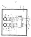
- a first embodiment 10 is shown, the housing 12 and one Housing cover portion 14 (not shown).
- the housing 12 has at the bottom Area two openings 20, 22 through which a lead 18 within a building wall and a return 16 from or to a central heating system is provided and passed through can be.
- the illustrated embodiment which is particularly suitable for single-pipe systems in central heating systems suitable, has a valve device after the flow and return 24 on, which can be dedicated to various purposes.
- This can, for example Shutting off the radiator to be connected and can also be provided optionally have a bypass controllable in its flow to both during a flow of heating medium during operation and during the shut-off of the radiator through the bypass.
- Further line sections can be attached to the valve fitting 24 connect, whereby an externally controllable valve can be provided in advance, For example, a thermostatic valve that has a recess in the front or the Cover 14 of the housing 12 can be adjusted.
- a shut-off valve 28 can also be provided are, this, as well as possibly the thermostatic valve 26, with in a Connection device could be integrated.
- heating medium can take up tightly, depending on the distance between the wall on which the Radiator is to be installed, and the radiator has different dimensional requirements to the connections through different receiving depths of the line sections 39a, 39b can be managed in the line sections 38a, 38b.
- Fig. 2 the Embodiment according to FIG. 1 shown in a plan view, the position of the housing 12 is clearly visible in the wall surrounding the housing 12.
- the protruding pipe sections 38a, 38b of the knees 30, 32 can also be seen better from FIG. 2.
- the line sections 38a, 38b are placed close together, so that the dimensions of the housing 12 can be minimized accordingly.
- the housing 12 can be made of plastic or metal and can also Anchoring sections have an improved fastening or anchoring within the walls of a building.
- FIG. 3 shows an embodiment with features according to the invention, which is already connected to a radiator 100.
- the line sections 39a, 39b are What can not be seen in Fig. 3 in the absence of a sectional view, approximately half in the corresponding line sections 38a, 38b from the knees 30, 32 according to FIG. 1 corresponding Knees housed. If there is a smaller distance between the wall and the radiator should be set or if a larger distance should be set, the line sections 39a, 39b can be pushed into the line sections 38a, 38b or be pulled out of these.
- Respective leg or angle sections 70 adjoin the line sections 39a, 39b to supply the heating medium to the radiator 100 to be connected.
- a connecting section 40 may be provided, which is preferably optically connected to the Appearance of the line sections 39a, 39b or the leg or angle sections 70 can be adapted.
- connection sections 38b, 38a, 39b, 39a can directly connect of the radiator at a corresponding distance from the wall or the correspondingly dimensioned housing 12 are led out, the connecting section then 40 must in principle be as long or wide as the one to be connected Radiator 100.
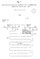
- Fig. 5 shows a connection arrangement by means of which a heater 100 and Underfloor heating 200 can be connected to the pipe system of a central heating system can. It should be noted that it is advantageous if so many components of the 5 and also according to FIGS. 6, 7a and 7b and preferred all connection components are included in the housing according to FIGS. 1 to 4 can, because this enables a particularly simple and visually appealing installation can be.
- a thermostatic valve 126 In the flow 142 from the central heating system (not shown) is a thermostatic valve 126 arranged to which a branch to a radiator flow 147 and Underfloor heating flow 148 connects.
- the heater 100 can by a connection fitting 149 can be connected, which makes it possible to lock the radiator and possibly bypassed at least partially by means of a bypass.
- a throttle device 141 In the return 143 of the Radiator 100, a throttle device 141 is provided, the higher line resistance takes into account the underfloor heating.
- the throttle device 141 Line resistance of the radiator 100 increased so that the current of the heating medium on Lead 142 can be divided in a meaningful way, so that both the radiator underfloor heating 200 can also make a contribution.
- At the return 146 of the underfloor heating 200 is a two-way valve with a temperature sensor arranged, which measures the temperature of the heating medium at the return 146 and the Passage of the heating medium through the floor heating 200 controls accordingly, so that which in a heating system with only one control level of the flow temperature of the Heating medium relatively high temperature of the heating medium, which is matched to the radiator corresponding to the delayed passage through the heating coils of the floor heating 200 can be regulated down.
- the respective returns 143 run beyond the valve 145, 146 together again and combine to form the central heating return 144.
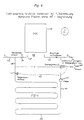
- a connection arrangement is proposed, in which different from the 5, the thermostatic valve 126 only after the derivation of the Flow 148 of the floor heating 200 is provided.
- Underfloor heating 200 is here a three-way valve is assigned, which bypasses 152 the heating medium used using a pump 151 again admixes the flow 148 of the underfloor heating 200.
- the temperature of the heating medium at the sensor 150 in the flow of the underfloor heating 200 measured where the flow from the central heating and the bypass 152 have been brought together.
- the temperature caused by the sensor 150 is measured, more or less used heating medium from the three-way valve 145a can be returned to the flow 148 to the flow temperature of the underfloor heating 200 within a reasonable temperature range.
- the thermostatic valve could be controlled 126 can be arranged before the branching of the flow 148 of the underfloor heating 200, such as this is shown in Fig. 7a.
- thermostatic valve 126 This preferred arrangement of the thermostatic valve according to FIG. 7a is achieved by a throttle valve 141 and the arrangement of the pump 151 in the return 146 of the underfloor heating 200 accompanied to take into account the changed temperature and heating medium pressure ratios to be able to. So even in the event that the thermostatic valve 126 is perfect is blocked, a sensible control sequence is possible, either the thermostatic valve 126 be coupled to the control of the three-way valve 145a or if the value falls below a certain temperature on the sensor 150, its activity and Stop the activity of the pump 151 and only start again when a minimum temperature has been reached is detected by the temperature sensor 150.
- FIG. 7b corresponds essentially to the function Embodiment according to FIG. 7a, but instead of an expensive one Three-way valve 145a in turn a two-way valve 145 in connection with a throttle device 153 is used in the bypass 152 to prevent the heating medium bypasses the heating coils of the underfloor heating system 200 because the flow resistance of the Underfloor heating 200 would in any case be less than that via the bypass 152 a throttle device 141 is also provided in the return 143 from the radiator.
Landscapes
- Engineering & Computer Science (AREA)
- Thermal Sciences (AREA)
- Chemical & Material Sciences (AREA)
- Combustion & Propulsion (AREA)
- Mechanical Engineering (AREA)
- General Engineering & Computer Science (AREA)
- Physics & Mathematics (AREA)
- Steam Or Hot-Water Central Heating Systems (AREA)
- Coupling Device And Connection With Printed Circuit (AREA)
- Connection Or Junction Boxes (AREA)
- Cartons (AREA)
- Auxiliary Devices For And Details Of Packaging Control (AREA)
- Photovoltaic Devices (AREA)
- Cable Accessories (AREA)
- Domestic Hot-Water Supply Systems And Details Of Heating Systems (AREA)
- Central Heating Systems (AREA)
Claims (30)
- Agencement de raccordement pour dispositifs de chauffage, de préférence des corps chauffants et des chauffages au sol, comportant un corps de réception (12, 14) pour des éléments d'installation de chauffage, tels qu'une soupape, un tronçon de conduite, une dérivation, qui comporte un boítier (12) avec un couvercle(14), le corps de réception, respectivement le boítier (12, 14), étant pourvu d'un trou aller et d'un trou retour (20, 22) pour l'aller et le retour respectivement vers et depuis l'installation de chauffage central, caractérisé en ce que sont prévus un embranchement de la conduite aller (142) du chauffage vers la conduite aller (147) du corps chauffant et vers la conduite aller (148) du chauffage au sol, ainsi que des dispositifs de commande pour le corps chauffant et des dispositifs de raccordement et de régulation pour le chauffage au sol dans le corps de réception (12, 14), et en ce que des trous aller et retour pour le passage des raccordements de l'aller et du retour du dispositif de chauffage sont disposés dans le corps de réception.
- Agencement selon la revendication 1, caractérisé en ce que les trous de raccordement de la conduite aller et de la conduite retour du corps chauffant sont prévus dans une partie frontale du boítier (12) ou dans le couvercle (14).
- Agencement selon l'une des revendications 1 ou 2, caractérisé en ce que le couvercle (14) et/ou un cache masquant ou recouvrant le couvercle (14) peuvent être ajustés au moins dans le plan du couvercle, du cache ou de la paroi.
- Agencement selon l'une des revendications 1 à 3, caractérisé en ce que le boítier (12, 14) présente en outre des trous pour l'aller et le retour vers un chauffage au sol (200).
- Agencement selon l'une des revendications 1 à 4, caractérisé en ce que les tronçons de conduite (38a, 38b, 39a, 39b) pour le raccordement du corps chauffant (100), qui s'étendent à l'extérieur du boítier (12, 14) vers le corps chauffant (100), peuvent être allongés ou raccourcis, notamment allongés ou raccourcis de manière télescopique.
- Agencement selon l'une des revendications 1 à 5, caractérisé en ce que dans le corps de réception, respectivement dans le boítier (12, 14), il est prévu au moins un tronçon de conduite flexible, de préférence deux tronçons de conduite flexible qui sont prévus dans l'aller et/ou le retour afin de compenser des tolérances ou des erreurs de montage.
- Agencement selon la revendication 6, caractérisé en ce que le ou les tronçon(s) de conduite flexible (36, 34) en matière plastique et/ou en métal est ou sont prévus devant ou derrière une soupape, respectivement un dispositif de raccordement (24, 26, 28), avec ou sans régulation du débit, dérivation, etc.
- Agencement selon l'une des revendications 1 à 7, caractérisé en ce que pour le raccordement du corps chauffant à l'agencement, il est monté entre l'aller et le retour un manchon, un tronçon de tube (40) ou similaire, qui relie notamment optiquement l'aller et le retour.
- Agencement selon l'une des revendications 1 à 8, caractérisé en ce que la partie frontale ou le couvercle (14) présente des tronçons de fixation pour des éléments décoratifs, notamment des carreaux.
- Agencement selon l'une des revendications 1 à 9, caractérisé en ce que la partie frontale ou le couvercle est pourvu d'un évidement pour une soupape ou une soupape thermostatique (26).
- Agencement selon l'une des revendications 1 à 10, caractérisé en ce que la partie frontale ou le couvercle (14) est pourvu d'au moins un évidement ou d'au moins une partie à fenêtre, par exemple pour un récepteur de télécommande, pour une lampe témoin d'un chauffage à résistance électrique.
- Agencement selon l'une des revendications 1 à 11, caractérisé en ce que l'ajustement s'effectue au moyen d'au moins un dispositif d'ajustement qui peut être réalisé par exemple au moyen de deux fentes longitudinales, une fente longitudinale pouvant être prévue dans une partie de boítier ou dans la partie frontale ou le couvercle et l'autre fente longitudinale dans la partie frontale ou le couvercle ou dans la partie de cache.
- Agencement selon l'une des revendications 1 à 12, caractérisé en ce qu'il est prévu un dispositif de régulation du débit (145, 145a) avec un dispositif à sonde de température (150) pour fluide de chauffage, dans le retour depuis le chauffage au sol (200).
- Agencement selon l'une des revendications 4 à 13, caractérisé en ce que l'embranchement aller pour la conduite aller (147) vers le corps chauffant (100) et vers la conduite aller (148) du chauffage au sol (200) est disposé derrière une soupape thermostatique pour la régulation du débit, en fonction de la température ambiante (126).
- Agencement selon l'une des revendications 4 à 13, caractérisé en ce que l'embranchement aller pour le chauffage au sol est disposé devant une soupape thermostatique pour la régulation du débit par le corps chauffant (100), en fonction de la température ambiante.
- Agencement selon la revendication 13, caractérisé en ce que le dispositif de régulation du débit est une soupape à deux voies qui est insérée dans la conduite de retour du chauffage au sol.
- Agencement selon la revendication 13, caractérisé en ce que le dispositif de régulation du débit est une soupape à trois voies et en ce qu'il est prévu une dérivation (152) entre la conduite aller du chauffage au sol et la conduite retour du chauffage au sol, ce qui fait que la soupape peut acheminer le fluide chauffant depuis le retour dans l'aller du chauffage au sol, en fonction de la position de régulation de la soupape à trois voies.
- Agencement selon la revendication 17, caractérisé en ce que dans l'aller ou le retour du chauffage au sol, il est prévu un dispositif de pompage (151), de préférence devant la soupape à trois voies (145a).
- Agencement selon l'une des revendications 13 à 18, caractérisé en ce que le dispositif à sonde de température (150) détecte la température du fluide chauffant du chauffage au sol, dans sa conduite aller (148), de préférence derrière l'embouchure d'une ou de la dérivation (152), ou de son retour.
- Agencement selon la revendication 16, caractérisé en ce qu'une dérivation (152) est prévue dans le chauffage au sol (200) et court-circuite la conduite retour avec sa conduite aller, la soupape à deux voies (145) étant disposée dans le retour du chauffage au sol (200), derrière l'embranchement vers la dérivation (152) dans le sens de l'écoulement.
- Agencement selon la revendication 20, caractérisé en ce qu'il est prévu dans la dérivation un dispositif (153) d'étranglement d'écoulement, qui exerce sa fonction d'étranglement dans le sens de l'écoulement.
- Agencement selon l'une des revendications 17 ou 18, caractérisé en ce que dans le retour du corps chauffant, il est prévu, devant l'embouchure du retour du chauffage au sol, un dispositif d'étranglement d'écoulement qui exerce sa fonction d'étranglement dans le sens contraire au sens de l'écoulement.
- Agencement selon l'une des revendications 1 à 22, caractérisé en ce qu'un dispositif à soupape thermostatique (126) est prévu pour la régulation du débit, en fonction de la température ambiante, dans la conduite aller (142) depuis l'installation de chauffage central, soit devant la conduite aller (147) du corps chauffant (100), soit devant la conduite aller (147) du corps chauffant et la conduite (148) du chauffage au sol.
- Agencement selon l'une des revendications 13 à 23, caractérisé en ce qu'au moins quelques-uns, de préférence tous les constituants du dispositif de raccordement et de régulation pour le chauffage au sol et/ou le corps chauffant, sont logés dans le corps de réception, respectivement le boítier (12, 14).
- Agencement selon l'une des revendications 13 à 23, caractérisé en ce qu'au moins quelques-uns, de préférence tous les composants de régulation et/ou de raccordement sont logés dans un bloc d'installation.
- Agencement selon l'une des revendications précédentes, comportant une conduite aller vers le corps chauffant, ainsi qu'une conduite retour depuis le corps chauffant, caractérisé par un tronçon de liaison (40) au dispositif de raccordement, entre la conduite aller du corps chauffant et la conduite retour du corps chauffant, ce qui fait qu'au moins l'espace intermédiaire compris entre l'aller (39b) et le retour (39a) est couvert.
- Agencement selon la revendication 26, caractérisé en ce que le tronçon de liaison (40) est monté sur l'aller et respectivement sur le retour de manière à les fixer.
- Agencement selon l'une des revendications 26 ou 27, caractérisé en ce que le tronçon de liaison (40) présente un évidement pour une tête de thermostat.
- Agencement selon l'une des revendications 26 à 28, caractérisé en ce que le tronçon de liaison (40) est identique ou comparable à des tronçons de chauffage du corps chauffant, notamment des tubes chauffants du corps chauffant.
- Agencement selon l'une des revendications précédentes, caractérisé en ce que le corps chauffant peut être relié, par des tronçons à branches ou des tronçons coudés (70), aux composants d'installation de chauffage, respectivement par l'intermédiaire de ceux-ci, au chauffage central.
Priority Applications (1)
| Application Number | Priority Date | Filing Date | Title |
|---|---|---|---|
| DE29724080U DE29724080U1 (de) | 1996-10-28 | 1997-10-24 | Anschlußkasten |
Applications Claiming Priority (3)
| Application Number | Priority Date | Filing Date | Title |
|---|---|---|---|
| DE19644773 | 1996-10-28 | ||
| DE19644773A DE19644773A1 (de) | 1996-10-28 | 1996-10-28 | Anschlußkasten |
| PCT/EP1997/005873 WO1998019111A1 (fr) | 1996-10-28 | 1997-10-24 | Boite de raccordement |
Publications (2)
| Publication Number | Publication Date |
|---|---|
| EP0934492A1 EP0934492A1 (fr) | 1999-08-11 |
| EP0934492B1 true EP0934492B1 (fr) | 2000-08-09 |
Family
ID=7810222
Family Applications (1)
| Application Number | Title | Priority Date | Filing Date |
|---|---|---|---|
| EP97948793A Expired - Lifetime EP0934492B1 (fr) | 1996-10-28 | 1997-10-24 | Boite de raccordement |
Country Status (8)
| Country | Link |
|---|---|
| EP (1) | EP0934492B1 (fr) |
| AT (1) | ATE195369T1 (fr) |
| AU (1) | AU6910298A (fr) |
| CZ (1) | CZ148299A3 (fr) |
| DE (3) | DE19644773A1 (fr) |
| DK (1) | DK0934492T3 (fr) |
| PL (1) | PL333067A1 (fr) |
| WO (1) | WO1998019111A1 (fr) |
Cited By (3)
| Publication number | Priority date | Publication date | Assignee | Title |
|---|---|---|---|---|
| WO2002075223A2 (fr) | 2001-03-19 | 2002-09-26 | Brinic B.V. | Ensemble raccord et bloc de raccord d'un systeme de chauffage central |
| CN111023245A (zh) * | 2019-12-20 | 2020-04-17 | 台州半城暖通科技有限公司 | 一种暖气片管道暗装引出盖及暖气片管道安装方式 |
| RU2746619C2 (ru) * | 2018-12-27 | 2021-04-19 | Акционерное Общество "Сантехпром" | Узел трубной обвязки прибора отопления (варианты) и способ обвязки (варианты) |
Families Citing this family (13)
| Publication number | Priority date | Publication date | Assignee | Title |
|---|---|---|---|---|
| DE29817525U1 (de) | 1998-10-01 | 1998-12-10 | Dumser Metallbau GmbH & Co. KG, 76829 Landau | Drei-Wege-Mischer für die Verwendung in einem Heizkreislauf, z.B. einer Warmwasserheizungsanlage |
| DE19912821C2 (de) * | 1999-03-22 | 2002-09-26 | Kermi Gmbh | Ventilanordnung |
| SM200100020B (it) * | 2001-10-15 | 2003-04-16 | R D Z S P A | Struttura di circuito idraulico, particolarmente per la distribuzione di acqua per riscaldamento o raffrescamento |
| DE10219196B4 (de) * | 2002-04-29 | 2010-03-18 | Kermi Gmbh | Anschlussarmatur |
| DE10323525B3 (de) * | 2003-05-24 | 2004-12-02 | Danfoss A/S | Heizungs-Ventileinheit |
| AT413756B (de) * | 2004-01-26 | 2006-05-15 | Wavin Bv | Raumklimaeinrichtung |
| DE202009015397U1 (de) * | 2009-11-16 | 2011-04-07 | Rehau Ag + Co. | Thermische Anschlussdose und diese umfassende Betonkerntemperierung |
| DE102011005365A1 (de) * | 2011-03-10 | 2012-09-13 | Michael Hertneck | Flächenheizeinrichtung und Anschlussbox |
| DE202014011121U1 (de) * | 2014-05-30 | 2017-12-22 | Peter Gabanyi | Raumtemperatur-Regelung für eine Flächenheizung |
| DE202016102366U1 (de) * | 2016-05-04 | 2017-08-07 | Rehau Ag & Co | Absperrdose für ein Betonkerntemperierungssystem und diese umfassendes Betonkerntemperierungssystem |
| DE102018130189B4 (de) * | 2018-11-28 | 2023-03-23 | Simplex Armaturen & Systeme Gmbh | Verfahren zum Betrieb einer Heizungsinstallation |
| CN112815536A (zh) * | 2021-03-08 | 2021-05-18 | 佛山缝叶鸟环境科技有限公司 | 一种混水装置及其淋浴系统 |
| FI129972B (fi) * | 2021-08-25 | 2022-11-30 | Jakotec Oy | Kytkentäkeskus, lattiarakennejärjestely ja menetelmä kytkentäkeskuksen asentamiseksi lattiarakenteen yhteyteen |
Family Cites Families (9)
| Publication number | Priority date | Publication date | Assignee | Title |
|---|---|---|---|---|
| DE7317641U (de) | 1973-11-29 | Steinbeisser G | Heizkörper Anschlußkonsole | |
| DE3431424A1 (de) | 1983-10-01 | 1985-04-11 | Josef 4417 Altenberge Plottek | Platzhalter fuer im mauerwerk einzusetzende versorgungseinrichtungen |
| DE8712495U1 (de) * | 1987-09-16 | 1987-10-29 | Fa. Franz Viegener Ii, 5952 Attendorn | Montage- und Kupplungsvorrichtung für einen an einer Wand festlegbaren Heizkörper |
| AT402969B (de) * | 1993-08-11 | 1997-10-27 | Schwarz A & Co | Anschlussvorrichtung für einen warmwasserheizkörper |
| DE9316361U1 (de) | 1993-10-26 | 1994-08-11 | Straßhofer GmbH, 80995 München | Heizkörper-Wandanschlußsystem für den Heizkörperanschluß in der Wand im Ein- und Zweirohrsystem |
| ATE172021T1 (de) * | 1994-02-23 | 1998-10-15 | Giacomini Spa | Hydraulische kopplung |
| DE19540703C2 (de) * | 1995-11-02 | 2003-12-11 | Hertneck Andrea | Fußbodenheizung mit Einzelraum-Temperaturregelung |
| DE29600266U1 (de) | 1996-01-09 | 1996-02-29 | U.S.H. Fittings + Kunststoffteile GmbH, 33689 Bielefeld | Fußbodenheizung |
| DE29611577U1 (de) | 1996-07-03 | 1996-09-05 | U.S.H. Fittings + Kunststoffteile GmbH, 33689 Bielefeld | Anschlußvorrichtung für Fußbodenheizung |
-
1996
- 1996-10-28 DE DE19644773A patent/DE19644773A1/de not_active Withdrawn
-
1997
- 1997-03-17 DE DE29704807U patent/DE29704807U1/de not_active Expired - Lifetime
- 1997-10-24 AU AU69102/98A patent/AU6910298A/en not_active Abandoned
- 1997-10-24 AT AT97948793T patent/ATE195369T1/de not_active IP Right Cessation
- 1997-10-24 DK DK97948793T patent/DK0934492T3/da active
- 1997-10-24 WO PCT/EP1997/005873 patent/WO1998019111A1/fr not_active Ceased
- 1997-10-24 EP EP97948793A patent/EP0934492B1/fr not_active Expired - Lifetime
- 1997-10-24 PL PL97333067A patent/PL333067A1/xx unknown
- 1997-10-24 DE DE59702160T patent/DE59702160D1/de not_active Expired - Fee Related
- 1997-10-24 CZ CZ991482A patent/CZ148299A3/cs unknown
Cited By (4)
| Publication number | Priority date | Publication date | Assignee | Title |
|---|---|---|---|---|
| WO2002075223A2 (fr) | 2001-03-19 | 2002-09-26 | Brinic B.V. | Ensemble raccord et bloc de raccord d'un systeme de chauffage central |
| RU2746619C2 (ru) * | 2018-12-27 | 2021-04-19 | Акционерное Общество "Сантехпром" | Узел трубной обвязки прибора отопления (варианты) и способ обвязки (варианты) |
| CN111023245A (zh) * | 2019-12-20 | 2020-04-17 | 台州半城暖通科技有限公司 | 一种暖气片管道暗装引出盖及暖气片管道安装方式 |
| CN111023245B (zh) * | 2019-12-20 | 2021-08-17 | 台州半城暖通科技有限公司 | 一种暖气片管道暗装引出盖及暖气片管道安装方式 |
Also Published As
| Publication number | Publication date |
|---|---|
| ATE195369T1 (de) | 2000-08-15 |
| EP0934492A1 (fr) | 1999-08-11 |
| PL333067A1 (en) | 1999-11-08 |
| DK0934492T3 (da) | 2000-12-18 |
| DE19644773A1 (de) | 1998-04-30 |
| DE29704807U1 (de) | 1997-06-05 |
| AU6910298A (en) | 1998-05-22 |
| WO1998019111A1 (fr) | 1998-05-07 |
| DE59702160D1 (de) | 2000-09-14 |
| CZ148299A3 (cs) | 1999-12-15 |
Similar Documents
| Publication | Publication Date | Title |
|---|---|---|
| EP0934492B1 (fr) | Boite de raccordement | |
| DE29600266U1 (de) | Fußbodenheizung | |
| DE19642721B4 (de) | Anschlußvorrichtung für einen geregelten Heizkessel zur Speisung und Regelung von zwei Heizkreisläufen | |
| DE102004014126B3 (de) | Sanitär-Armatur zur Unterputz-Montage | |
| DE19912284B4 (de) | Kompaktheizungsanlage | |
| DE102009041610B4 (de) | Luftführungssystem zur Belüftung von Räumen eines Gebäudes | |
| DE3203964C2 (de) | Abzweigeeinheit für eine Heizungs- oder Kühlanlage | |
| DE19909780A1 (de) | Armaturenmodul für ein Heizungs- und/oder Warmwasserleitungssystem eines Gebäudes | |
| EP0763181B1 (fr) | Dispositif de chauffage | |
| EP3696332B1 (fr) | Robinetterie sanitaire à commande électrique | |
| DE102010055804A1 (de) | Modulares Unterputz-System mit einem zentralen Unterputz-Mischmodul | |
| DE19750109C2 (de) | Anschlußgarnitur und Heizkörper | |
| DE29724080U1 (de) | Anschlußkasten | |
| EP1435480B1 (fr) | Robinetterie sanitaire | |
| DE102006055756B4 (de) | Sanitäreinrichtung mit einem tafelartigen Grundkörper | |
| EP0700501B1 (fr) | Raccord pour le raccordement a leur source de chaleur de radiateurs faisant partie du circuit de chauffage de l'installation de chauffage d'un batiment | |
| EP2543780A1 (fr) | Module et système de douche doté d'une commande électronique | |
| DE19649937C2 (de) | Badewannenarmatur mit integrierter Schmutzwasserrücklaufsicherung | |
| DE29504520U1 (de) | Heizvorrichtung mit einer Verkleidung sowie Verkleidung für eine Heizvorrichtung | |
| DE3712625C2 (fr) | ||
| DE20305054U1 (de) | Vorrichtung zum gemeinsamen Anschluß eines Heizkörpers und einer Fußbodenheizung an einen Heizungskreislauf | |
| EP2386693B1 (fr) | Armature de table de lavage dotée d'un élément de limitation de température de sécurité | |
| DE10060704A1 (de) | Wasserauslaufarmatur für Waschbecken | |
| DE20201216U1 (de) | Kombinierte Badheizkörper- und Fußbodenheizung | |
| DE10111578C1 (de) | Sanitäre Wandarmatur |
Legal Events
| Date | Code | Title | Description |
|---|---|---|---|
| PUAI | Public reference made under article 153(3) epc to a published international application that has entered the european phase |
Free format text: ORIGINAL CODE: 0009012 |
|
| 17P | Request for examination filed |
Effective date: 19990423 |
|
| AK | Designated contracting states |
Kind code of ref document: A1 Designated state(s): AT DE DK FR GB IT |
|
| GRAG | Despatch of communication of intention to grant |
Free format text: ORIGINAL CODE: EPIDOS AGRA |
|
| GRAG | Despatch of communication of intention to grant |
Free format text: ORIGINAL CODE: EPIDOS AGRA |
|
| GRAH | Despatch of communication of intention to grant a patent |
Free format text: ORIGINAL CODE: EPIDOS IGRA |
|
| 17Q | First examination report despatched |
Effective date: 20000114 |
|
| RBV | Designated contracting states (corrected) |
Designated state(s): AT DE DK FR GB IT |
|
| GRAH | Despatch of communication of intention to grant a patent |
Free format text: ORIGINAL CODE: EPIDOS IGRA |
|
| GRAA | (expected) grant |
Free format text: ORIGINAL CODE: 0009210 |
|
| ITF | It: translation for a ep patent filed | ||
| AK | Designated contracting states |
Kind code of ref document: B1 Designated state(s): AT DE DK FR GB IT |
|
| REF | Corresponds to: |
Ref document number: 195369 Country of ref document: AT Date of ref document: 20000815 Kind code of ref document: T |
|
| GBT | Gb: translation of ep patent filed (gb section 77(6)(a)/1977) |
Effective date: 20000809 |
|
| REF | Corresponds to: |
Ref document number: 59702160 Country of ref document: DE Date of ref document: 20000914 |
|
| PGFP | Annual fee paid to national office [announced via postgrant information from national office to epo] |
Ref country code: DK Payment date: 20001002 Year of fee payment: 4 |
|
| ET | Fr: translation filed | ||
| REG | Reference to a national code |
Ref country code: DK Ref legal event code: T3 |
|
| PLBE | No opposition filed within time limit |
Free format text: ORIGINAL CODE: 0009261 |
|
| STAA | Information on the status of an ep patent application or granted ep patent |
Free format text: STATUS: NO OPPOSITION FILED WITHIN TIME LIMIT |
|
| 26N | No opposition filed | ||
| PGFP | Annual fee paid to national office [announced via postgrant information from national office to epo] |
Ref country code: FR Payment date: 20011003 Year of fee payment: 5 |
|
| PGFP | Annual fee paid to national office [announced via postgrant information from national office to epo] |
Ref country code: DE Payment date: 20011004 Year of fee payment: 5 |
|
| PGFP | Annual fee paid to national office [announced via postgrant information from national office to epo] |
Ref country code: AT Payment date: 20011005 Year of fee payment: 5 |
|
| PG25 | Lapsed in a contracting state [announced via postgrant information from national office to epo] |
Ref country code: GB Free format text: LAPSE BECAUSE OF NON-PAYMENT OF DUE FEES Effective date: 20011024 Ref country code: DK Free format text: LAPSE BECAUSE OF NON-PAYMENT OF DUE FEES Effective date: 20011024 |
|
| REG | Reference to a national code |
Ref country code: GB Ref legal event code: IF02 |
|
| REG | Reference to a national code |
Ref country code: DK Ref legal event code: EBP |
|
| GBPC | Gb: european patent ceased through non-payment of renewal fee |
Effective date: 20011024 |
|
| PG25 | Lapsed in a contracting state [announced via postgrant information from national office to epo] |
Ref country code: AT Free format text: LAPSE BECAUSE OF NON-PAYMENT OF DUE FEES Effective date: 20021024 |
|
| PG25 | Lapsed in a contracting state [announced via postgrant information from national office to epo] |
Ref country code: DE Free format text: LAPSE BECAUSE OF NON-PAYMENT OF DUE FEES Effective date: 20030501 |
|
| PG25 | Lapsed in a contracting state [announced via postgrant information from national office to epo] |
Ref country code: FR Free format text: LAPSE BECAUSE OF NON-PAYMENT OF DUE FEES Effective date: 20030630 |
|
| REG | Reference to a national code |
Ref country code: FR Ref legal event code: ST |
|
| PG25 | Lapsed in a contracting state [announced via postgrant information from national office to epo] |
Ref country code: IT Free format text: LAPSE BECAUSE OF NON-PAYMENT OF DUE FEES Effective date: 20051024 |