EP0934494B1 - Kühlkreislaufeinrichtung für eine kälteanlage - Google Patents
Kühlkreislaufeinrichtung für eine kälteanlage Download PDFInfo
- Publication number
- EP0934494B1 EP0934494B1 EP98944909A EP98944909A EP0934494B1 EP 0934494 B1 EP0934494 B1 EP 0934494B1 EP 98944909 A EP98944909 A EP 98944909A EP 98944909 A EP98944909 A EP 98944909A EP 0934494 B1 EP0934494 B1 EP 0934494B1
- Authority
- EP
- European Patent Office
- Prior art keywords
- evaporator
- refrigerant fluid
- valve
- circuit arrangement
- refrigeration circuit
- Prior art date
- Legal status (The legal status is an assumption and is not a legal conclusion. Google has not performed a legal analysis and makes no representation as to the accuracy of the status listed.)
- Expired - Lifetime
Links
Images


Classifications
-
- F—MECHANICAL ENGINEERING; LIGHTING; HEATING; WEAPONS; BLASTING
- F25—REFRIGERATION OR COOLING; COMBINED HEATING AND REFRIGERATION SYSTEMS; HEAT PUMP SYSTEMS; MANUFACTURE OR STORAGE OF ICE; LIQUEFACTION SOLIDIFICATION OF GASES
- F25B—REFRIGERATION MACHINES, PLANTS OR SYSTEMS; COMBINED HEATING AND REFRIGERATION SYSTEMS; HEAT PUMP SYSTEMS
- F25B41/00—Fluid-circulation arrangements
- F25B41/30—Expansion means; Dispositions thereof
- F25B41/31—Expansion valves
- F25B41/33—Expansion valves with the valve member being actuated by the fluid pressure, e.g. by the pressure of the refrigerant
- F25B41/335—Expansion valves with the valve member being actuated by the fluid pressure, e.g. by the pressure of the refrigerant via diaphragms
Definitions
- the condensation pressure is that necessary to achieve the transformation of the refrigerant fluid to a gaseous form in the condenser 4 and the suction pressure is that obtained by operation of the compressor.
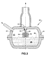
- the valve body 21 defines, internally, a chamber 27 for the passage of refrigerant fluid and communicating with the condensed fluid outlet 5 of the condenser 4 through the valve seat 24 and, continuously, with the condensed fluid inlet 9 of the evaporator 8, through the opening 23.
- the spring element 26 is in the form of a diaphragm defining a wall of the chamber 27 for the passage of refrigerant fluid opposite to the valve seat 24.
- the spring element 26 is mounted in the valve body 21, so as to constantly force the sealing means 25 to the closing condition of the refrigerant fluid passage 22.
- the spring element 26 has a sealing position, which is obtained when the hermetic compressor 1 is turned off, and a plurality of fluid passage positions, which are obtained by the elastic deformation of the spring element 26 when suction occurs in the chamber 27 for the passage of refrigerant fluid.
Landscapes
- Physics & Mathematics (AREA)
- Engineering & Computer Science (AREA)
- Fluid Mechanics (AREA)
- Mechanical Engineering (AREA)
- Thermal Sciences (AREA)
- General Engineering & Computer Science (AREA)
- Compressor (AREA)
- Devices That Are Associated With Refrigeration Equipment (AREA)
- Compression-Type Refrigeration Machines With Reversible Cycles (AREA)
- Details Of Measuring And Other Instruments (AREA)
- Motor Or Generator Cooling System (AREA)
- Temperature-Responsive Valves (AREA)
Claims (10)
- Kühlkreislaufanordnung für ein Kühlsystem, mit einem hermetischen Verdichter (1), einem Kondensator (4), der einen an einen Abzugsauslaß des Verdichters (1) angeschlossenen Einlaß und einen Auslaß aufweist, mit einem Verdampfer (8), der einen an den Auslaß des Kondensators (4) angeschlossenen Einlaß und einen Auslaß aufweist, und zudem mit einem zwischen dem Auslaß des Kondensators (4) und dem Einlaß des Verdampfers (8) angeordneten Ventil (20) zur Kühlfluid-Durchflußsteuerung, das mit einem Kühlfluiddurchlaß (22) versehen ist, dessen Querschnitt sich während des Betriebs des hermetischen Verdichters (1), abhängig von einer Kraft, die vom Kondensationsdruck stromaufwärts des Ventils (20) und vom Saugdruck stromabwärts des Ventils (20) herrührt, umgekehrt proportional zur Änderung der Kondensationstemperatur ändert, damit das dem Verdampfer (8) zugeführte kondensierte Kühlfluid eine Temperatur aufweist, die im wesentlichen einer nominalen Kondensationstemperatur des Systems entspricht, wobei der Querschnitt des Kühlfluiddurchlasses (22) geschlossen ist und die Fluidverbindung zwischen dem Kondensator (4) und dem Verdampfer (8) dabei vollständig unterbrochen wird, wenn der hermetische Verdichter (1) abschaltet.
- Kühlkreislaufanordnung nach Anspruch 1, bei der das Ventil (20) ein Dichtungsmittel (25) umfaßt, das in Wirkverbindung mit dem Kühlfluiddurchlaß (22) steht und unmittelbar und gleichzeitig dem Kondensationsdruck sowie dem Saugdruck ausgesetzt ist, wobei das Dichtungsmittel (25) abhängig von der durch diese Drücke bedingten Kraft verschoben wird, damit die Querschnittsänderung durch die Kühlfluid-Kondensationstemperatur des kondensierten Kühlfluids erfolgen kann.
- Kühlkreislaufanordnung nach Anspruch 2, bei welcher der Kühlfluiddurchlaß (22) durch einen zwischen einem Ventilsitz (24) und dem Dichtungsmittel (25) gebildeten ringförmigen Raum festgelegt ist.
- Kühlkreislaufanordnung nach Anspruch 3, bei der das Ventil (20) einen Ventilkörper (21) umfaßt, der in seinem Inneren eine Kammer (27) zum Durchlaß von Kühlfluid festlegt, die durch den Ventilsitz (24) in Verbindung mit dem Auslaß des Kondensators (4) steht und mit einer Öffnung (23) versehen ist, die in ständiger Fluidverbindung mit dem Einlaß des Verdampfers (8) steht.
- Kühlkreislaufanordnung nach Anspruch 4, bei der das Dichtungsmittel (25) einen Dichtabschnitt, der stromaufwärts des Ventilsitzes (24) liegt, und einen stromabwärts des Ventilsitzes gelegenen Antriebsabschnitt umfaßt, der mit dem Ventilkörper (21) über ein Federelement (26) verbunden ist, welches das Dichtungsmittel (25) ständig in den Verschlußzustand des Kühlfluiddurchlasses (22) drückt, wobei das Federelement (26) eine Dichtungsstellung, die erreicht wird, wenn der hermetische Verdichter (1) abschaltet, und mindestens eine Vielzahl von Fluiddurchlaßstellungen aufweist, die durch eine elastische Verformung des Federelementes (26) erreicht werden, wenn in der Kammer (27) zum Durchlaß von Kühlfluid ein Sog herrscht.
- Kühlkreislaufanordnung nach Anspruch 5, bei der das Federelement (26) in Form einer Membran vorliegt, die eine Wand der Kammer (27) gegenüber dem Ventilsitz (24) festlegt.
- Kühlkreislaufanordnung nach Anspruch 6, bei der das Federelement (26) im Inneren des Ventilkörpers (21) angeordnet ist, um letzteren in die Kammer (27) zum Durchlaß von Kühlfluid und in eine hermetische Kammer (28) zu unterteilen, die ein Fluid enthält, welches auf Temperaturveränderungen des Verdampfers (8) anspricht.
- Kühlkreislaufanordnung nach Anspruch 7, bei der das wärmeempfindliche Fluid in dem Federelement (26) wirkt, um letzteres zur Dichtungsstellung hin zu drücken, wenn die Temperatur des Verdampfers (8) fällt, und das Federelement (26) in jede Fluiddurchlaßstellung zu überführen, wenn die Temperatur des Verdampfers (8) steigt.
- Kühlkreislaufanordnung nach Anspruch 7, bei welcher der Ventilkörper (21) hermetisch ausgebildet und in dem Verdampfer (8) neben dessen Einlaß für kondensiertes Fluid angebracht ist.
- Kühlkreislaufanordnung nach Anspruch 9, bei welcher der Antriebsabschnitt des Dichtungsmittels (25) verstellbar mit dem Federelement (26) verbunden ist.
Applications Claiming Priority (3)
| Application Number | Priority Date | Filing Date | Title |
|---|---|---|---|
| BR9702803 | 1997-08-28 | ||
| BR9702803A BR9702803A (pt) | 1997-08-28 | 1997-08-28 | Arranjo para circuito de refrigeração de sistema de refrigeração |
| PCT/BR1998/000067 WO1999011987A1 (en) | 1997-08-28 | 1998-08-28 | A refrigeration circuit arrangement for a refrigeration system |
Publications (2)
| Publication Number | Publication Date |
|---|---|
| EP0934494A1 EP0934494A1 (de) | 1999-08-11 |
| EP0934494B1 true EP0934494B1 (de) | 2003-10-22 |
Family
ID=4067303
Family Applications (1)
| Application Number | Title | Priority Date | Filing Date |
|---|---|---|---|
| EP98944909A Expired - Lifetime EP0934494B1 (de) | 1997-08-28 | 1998-08-28 | Kühlkreislaufeinrichtung für eine kälteanlage |
Country Status (8)
| Country | Link |
|---|---|
| EP (1) | EP0934494B1 (de) |
| JP (1) | JP2001505296A (de) |
| KR (1) | KR20000068849A (de) |
| CN (1) | CN1237240A (de) |
| AT (1) | ATE252714T1 (de) |
| BR (1) | BR9702803A (de) |
| DE (1) | DE69819127D1 (de) |
| WO (1) | WO1999011987A1 (de) |
Families Citing this family (7)
| Publication number | Priority date | Publication date | Assignee | Title |
|---|---|---|---|---|
| US7895003B2 (en) | 2007-10-05 | 2011-02-22 | Emerson Climate Technologies, Inc. | Vibration protection in a variable speed compressor |
| US9541907B2 (en) | 2007-10-08 | 2017-01-10 | Emerson Climate Technologies, Inc. | System and method for calibrating parameters for a refrigeration system with a variable speed compressor |
| US8459053B2 (en) | 2007-10-08 | 2013-06-11 | Emerson Climate Technologies, Inc. | Variable speed compressor protection system and method |
| US8418483B2 (en) | 2007-10-08 | 2013-04-16 | Emerson Climate Technologies, Inc. | System and method for calculating parameters for a refrigeration system with a variable speed compressor |
| US8539786B2 (en) | 2007-10-08 | 2013-09-24 | Emerson Climate Technologies, Inc. | System and method for monitoring overheat of a compressor |
| JP7349706B2 (ja) * | 2019-07-04 | 2023-09-25 | 株式会社不二工機 | パワーエレメント及びこれを用いた膨張弁 |
| US11206743B2 (en) | 2019-07-25 | 2021-12-21 | Emerson Climate Technolgies, Inc. | Electronics enclosure with heat-transfer element |
Family Cites Families (5)
| Publication number | Priority date | Publication date | Assignee | Title |
|---|---|---|---|---|
| US3320763A (en) * | 1965-11-19 | 1967-05-23 | Westinghouse Electric Corp | Controls for refrigeration systems |
| US3638446A (en) * | 1969-06-27 | 1972-02-01 | Robert T Palmer | Low ambient control of subcooling control valve |
| US5245836A (en) * | 1989-01-09 | 1993-09-21 | Sinvent As | Method and device for high side pressure regulation in transcritical vapor compression cycle |
| US5201190A (en) * | 1992-02-24 | 1993-04-13 | White Consolidated Industries, Inc. | Refrigerator with subcooling flow control valve |
| EP0762064A1 (de) * | 1995-09-08 | 1997-03-12 | Fritz Ing. Weider | Durchsatzregelung für das Kältemittel einer Wärmepumpe und Verfahren |
-
1997
- 1997-08-28 BR BR9702803A patent/BR9702803A/pt not_active IP Right Cessation
-
1998
- 1998-08-28 KR KR1019997003702A patent/KR20000068849A/ko not_active Ceased
- 1998-08-28 JP JP51606499A patent/JP2001505296A/ja active Pending
- 1998-08-28 EP EP98944909A patent/EP0934494B1/de not_active Expired - Lifetime
- 1998-08-28 WO PCT/BR1998/000067 patent/WO1999011987A1/en not_active Ceased
- 1998-08-28 AT AT98944909T patent/ATE252714T1/de not_active IP Right Cessation
- 1998-08-28 CN CN98801227A patent/CN1237240A/zh active Pending
- 1998-08-28 DE DE69819127T patent/DE69819127D1/de not_active Expired - Lifetime
Also Published As
| Publication number | Publication date |
|---|---|
| WO1999011987A1 (en) | 1999-03-11 |
| EP0934494A1 (de) | 1999-08-11 |
| JP2001505296A (ja) | 2001-04-17 |
| CN1237240A (zh) | 1999-12-01 |
| BR9702803A (pt) | 1999-05-18 |
| DE69819127D1 (de) | 2003-11-27 |
| ATE252714T1 (de) | 2003-11-15 |
| KR20000068849A (ko) | 2000-11-25 |
Similar Documents
| Publication | Publication Date | Title |
|---|---|---|
| US5101640A (en) | Air conditioning apparatus, heat exchanger for use in the apparatus and apparatus control method | |
| KR950005386B1 (ko) | 냉동사이클장치 | |
| EP0279622B1 (de) | Steuerungseinrichtung für einen Kältekreislauf | |
| US5071321A (en) | Variable displacement refrigerant compressor passive destroker | |
| US20050120730A1 (en) | Heat pump water heating system including a compressor having a variable clearance volume | |
| US6997001B2 (en) | Method of operating a refrigeration cycle | |
| EP0934494B1 (de) | Kühlkreislaufeinrichtung für eine kälteanlage | |
| CN114739047B (zh) | 一种热泵热水机及其压缩机排气温度的控制方法 | |
| JPH04295566A (ja) | エンジン駆動式空気調和機 | |
| JP2516986B2 (ja) | 車両空調用冷凍回路 | |
| US4432705A (en) | Refrigeration compressor capacity control means and method | |
| KR20100064835A (ko) | 멀티형 공기조화기 및 그 운전 방법 | |
| JPH0689741B2 (ja) | 容量制御弁 | |
| US3962884A (en) | Piloted freeze throttling valve | |
| EP1994278A1 (de) | Schieberventil mit heissgasumgehungskanal | |
| JPH06159270A (ja) | 過熱防止装置を備えたスクロール圧縮機 | |
| US6966195B2 (en) | Air conditioning system | |
| KR960002567B1 (ko) | 냉동회로 | |
| US4890985A (en) | Air conditioning system with variable capacity compressor | |
| GB2068522A (en) | Temperature-sensitive control system | |
| JP3712827B2 (ja) | 冷凍冷蔵装置、冷媒流量補正用バイパス弁および温度膨張弁 | |
| EP0009145B1 (de) | Vorrichtung zur Leistungsregelung eines Kühlkompressors | |
| JP3481243B2 (ja) | 小型冷凍システム用始動装置 | |
| JPH10176864A (ja) | 可変容量圧縮機を用いた冷凍サイクル | |
| JP2006249969A (ja) | 可変容量式圧縮機の制御装置 |
Legal Events
| Date | Code | Title | Description |
|---|---|---|---|
| PUAI | Public reference made under article 153(3) epc to a published international application that has entered the european phase |
Free format text: ORIGINAL CODE: 0009012 |
|
| 17P | Request for examination filed |
Effective date: 19990322 |
|
| AK | Designated contracting states |
Kind code of ref document: A1 Designated state(s): AT DE ES FR GB IT |
|
| 17Q | First examination report despatched |
Effective date: 20020211 |
|
| GRAH | Despatch of communication of intention to grant a patent |
Free format text: ORIGINAL CODE: EPIDOS IGRA |
|
| GRAS | Grant fee paid |
Free format text: ORIGINAL CODE: EPIDOSNIGR3 |
|
| GRAA | (expected) grant |
Free format text: ORIGINAL CODE: 0009210 |
|
| AK | Designated contracting states |
Kind code of ref document: B1 Designated state(s): AT DE ES FR GB IT |
|
| PG25 | Lapsed in a contracting state [announced via postgrant information from national office to epo] |
Ref country code: AT Free format text: LAPSE BECAUSE OF FAILURE TO SUBMIT A TRANSLATION OF THE DESCRIPTION OR TO PAY THE FEE WITHIN THE PRESCRIBED TIME-LIMIT Effective date: 20031022 |
|
| REG | Reference to a national code |
Ref country code: GB Ref legal event code: FG4D |
|
| REF | Corresponds to: |
Ref document number: 69819127 Country of ref document: DE Date of ref document: 20031127 Kind code of ref document: P |
|
| PG25 | Lapsed in a contracting state [announced via postgrant information from national office to epo] |
Ref country code: DE Free format text: LAPSE BECAUSE OF FAILURE TO SUBMIT A TRANSLATION OF THE DESCRIPTION OR TO PAY THE FEE WITHIN THE PRESCRIBED TIME-LIMIT Effective date: 20040123 |
|
| PG25 | Lapsed in a contracting state [announced via postgrant information from national office to epo] |
Ref country code: ES Free format text: LAPSE BECAUSE OF FAILURE TO SUBMIT A TRANSLATION OF THE DESCRIPTION OR TO PAY THE FEE WITHIN THE PRESCRIBED TIME-LIMIT Effective date: 20040202 |
|
| ET | Fr: translation filed | ||
| PLBE | No opposition filed within time limit |
Free format text: ORIGINAL CODE: 0009261 |
|
| STAA | Information on the status of an ep patent application or granted ep patent |
Free format text: STATUS: NO OPPOSITION FILED WITHIN TIME LIMIT |
|
| PG25 | Lapsed in a contracting state [announced via postgrant information from national office to epo] |
Ref country code: GB Free format text: LAPSE BECAUSE OF NON-PAYMENT OF DUE FEES Effective date: 20040828 |
|
| 26N | No opposition filed |
Effective date: 20040723 |
|
| GBPC | Gb: european patent ceased through non-payment of renewal fee |
Effective date: 20040828 |
|
| PG25 | Lapsed in a contracting state [announced via postgrant information from national office to epo] |
Ref country code: FR Free format text: LAPSE BECAUSE OF NON-PAYMENT OF DUE FEES Effective date: 20050429 |
|
| REG | Reference to a national code |
Ref country code: FR Ref legal event code: ST |
|
| PG25 | Lapsed in a contracting state [announced via postgrant information from national office to epo] |
Ref country code: IT Free format text: LAPSE BECAUSE OF NON-PAYMENT OF DUE FEES Effective date: 20050828 |