EP0934607B1 - Hybridenergiespeichersystem - Google Patents
Hybridenergiespeichersystem Download PDFInfo
- Publication number
- EP0934607B1 EP0934607B1 EP97945356A EP97945356A EP0934607B1 EP 0934607 B1 EP0934607 B1 EP 0934607B1 EP 97945356 A EP97945356 A EP 97945356A EP 97945356 A EP97945356 A EP 97945356A EP 0934607 B1 EP0934607 B1 EP 0934607B1
- Authority
- EP
- European Patent Office
- Prior art keywords
- energy storage
- battery
- storage system
- storage device
- batteries
- Prior art date
- Legal status (The legal status is an assumption and is not a legal conclusion. Google has not performed a legal analysis and makes no representation as to the accuracy of the status listed.)
- Expired - Lifetime
Links
Images
Classifications
-
- H—ELECTRICITY
- H02—GENERATION; CONVERSION OR DISTRIBUTION OF ELECTRIC POWER
- H02J—ELECTRIC POWER NETWORKS; CIRCUIT ARRANGEMENTS OR SYSTEMS FOR SUPPLYING OR DISTRIBUTING ELECTRIC POWER; SYSTEMS FOR STORING ELECTRIC ENERGY
- H02J7/00—Circuit arrangements for charging or discharging batteries or for supplying loads from batteries
- H02J7/34—Parallel operation in networks using both storage and other DC sources, e.g. providing buffering
-
- H—ELECTRICITY
- H01—ELECTRIC ELEMENTS
- H01M—PROCESSES OR MEANS, e.g. BATTERIES, FOR THE DIRECT CONVERSION OF CHEMICAL ENERGY INTO ELECTRICAL ENERGY
- H01M16/00—Structural combinations of different types of electrochemical generators
Definitions
- This invention relates in general to energy storage devices, and in particular to hybrid rechargeable energy storage devices which provide high power and high capacity for portable electronic devices.
- the energy storage device such as a battery
- the battery becomes unable to provide current at a required level.
- the battery may retain a substantial charge, it is useless to the device to which it is attached.
- This problem is exacerbated when the device to which the battery is attached requires high power (i.e., current pulses) in an operating cycle which otherwise requires a much lower operating current.
- high power i.e., current pulses
- portable communications devices such as digital two-way radios and cellular phones when in the transmit mode.
- These power pulses or spikes require significantly higher current outputs than when the device is receiving or in standby mode.
- WO 97/12415 (which is part of the state of the art only when considering novelty as per Article 54(3) EPC), which describes a power source having a first component, for example, a battery, for delivering a substantially constant output, and a second component, i.e.., a capacitor, which delivers power in response to the power pulses and spikes required by the application device. While this type of power source well addresses the needs of pulsed power application devices, it does not address the fact that charging conditions may require a different trigger point at which the second component is activated. These conditions may be environmental, such as low temperature, or a function of the age of the power source. Failure to recognize the effect of charged condition may also have the deleterious effect of shrinking the life of the power source.
- an energy source which is capable of providing sufficient power for the high power pulses required of certain devices, while extending the usable life of the energy source.
- Such a device should be relatively small, and capable of being easily sized and shaped for a given application. Moreover, such a device should be able to recognize charging internal conditions, and alter its response as a function of the charged condition.
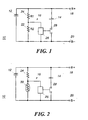
- the device 10 includes a first energy source 12 having a high energy density, and a high capacity, but which may not be able to provide high power as required by certain applications.
- the first energy source 12 may thus be one or more conventional battery cells, examples of which include, but are not limited to, a lead-acid battery, a nickel-cadmium battery, a nickel-metal hydride battery, a lithium ion battery, a lithium polymer battery, a lithium ion polymer electrolyte battery, a zinc air battery, and combinations thereof.
- the battery cell or cells may also be a primary battery, such as a conventional alkaline battery or even a compact portable fuel cell.
- the battery cell or cells may be disposed in a battery pack.
- the diagram 10 also shows that connected electrically in parallel with the first energy source 12, is a second energy source 14.
- the second energy source is capable of delivering a burst of high power, as may be required by a particular application.
- the second energy source 14 is preferably an electrochemical capacitor.
- the electrochemical capacitor devices typically include at least one electrode fabricated of a metal oxide material such as RuO 2 .
- the second electrode may also be a similar or different metal oxide, or may be of another type of material altogether.
- the second electrode may be a polymer such as polyanile, polypyrrole, polyurethane, polyacrylomide and combinations thereof.
- One or both of the electrodes may be fabricated of a carbon based material.
- the electrolyte may be alkaline, proton conducting, or organic solvent based.
- the capacitor is a thin device including a first electrode, a second electrode, and an electrolyte disposed therebetween.
- the capacitor may be fabricated as disclosed in one or more of United States Patent Application Serial Nos. 08/415,976 to Bai, et al, entitled “Electrochemical Capacitor and Method of Making Same”; 08/414,816 to Bai, et al entitled “Electrochemical Charge Storage Device Having Constant Voltage Discharge”; 08/513,648 to Bai, et al, entitled Electrochemical Cell Having Solid Polymer Electrolyte and Asymmetrical Inorganic Electrodes; 08/340,957 to Howard, et al., entitled “Polymer Gel Electrolyte and Electrochemical Capacitor Device Using Same”; 08/505,427 to Howard, entitled “Conducting Polymer Electrodes for Energy Storage Devices and Method of Making Same”; 08/358,294 to Li, et al, entitled “Electrode Material and Electrochemical Devices
- Electronic circuitry 16 Electrically connected between the first and second energy sources is electronic circuitry 16 adapted to determine which energy source to use in response to power demands from an associated electronic device.
- electronic circuitry 16 adapted to determine which energy source to use in response to power demands from an associated electronic device.
- Pulsed power communication devices such as digital cellular phones, two-way radios, and talk-back pagers all make such demands of their associated energy sources.
- the load which draws current is connected to the energy storage device at contacts 18 and 20.
- circuitry 16 must be adapted to determine which power source is best suited to respond to the power spike. For example, without circuitry, if the second power source delivers power only in response to a spike of greater than a pre-determined value, conditions may arise in which the first power source cannot respond, and the second power source will not respond since the triggering conditions have not been met. For example, as a battery ages, its internal impedance increases, thus rendering it less able to respond to any power spikes. Likewise, at low temperatures, i.e., less than about 0°C, most batteries' impedance increase. In either of these cases, a power spike below the capacitor threshold will not trigger the capacitor while conditions have changed such that the battery cannot respond. The result in both cases is that the load connected at the contacts will fail.
- circuitry 16 includes first and second resistors 22 and 24 to provide a measure of the impedance of the battery 12. As impedance changes due to changing internal factors, a controller 26 responds to changes in impedance and activates a switch 28 to electrically couple the capacitor 14 to the load. If the impedance change does not exceed a predetermined threshold, then the battery remains coupled to the load.
- one resistor may be replaced with a thermistor 30.
- the circuitry is particularly responsive to changes in impedance resulting from temperature changes.
- the controller enables the switch 28 to couple the capacitor 14 to the load.
- pulse currents are more acute under certain extreme conditions.
- certain battery types such as lithium ion batteries
- lithium ion batteries are adversely affected by excess heat. Accordingly, when the temperature of a lithium ion cell is elevated, its ability to respond to the burst current required of a digital cellular phone, may be compromised.
- nickel metal hydride batteries can deliver significantly less than full power (on the order of less than 40% of stored energy) at low temperatures. Accordingly, at temperatures as low as 0°C the performance of a nickel metal hydride battery may be so severely compromised that it cannot power a digital cellular phone.
Landscapes
- Engineering & Computer Science (AREA)
- Power Engineering (AREA)
- Chemical & Material Sciences (AREA)
- Chemical Kinetics & Catalysis (AREA)
- Electrochemistry (AREA)
- General Chemical & Material Sciences (AREA)
- Charge And Discharge Circuits For Batteries Or The Like (AREA)
- Electric Double-Layer Capacitors Or The Like (AREA)
- Direct Current Feeding And Distribution (AREA)
- Hybrid Cells (AREA)
- Secondary Cells (AREA)
- Battery Electrode And Active Subsutance (AREA)
Claims (9)
- Energie-Speichersystem (10), welches Folgendes aufweist:eine erste Energie-Speichervorrichtung (12), welche aus einer Batterie mit einer Impedanz zur Bereitstellung einer im Wesentlichen konstanten Nutzleistung gebildet ist;eine zweite Energie-Speichervorrichtung (14), welche mit der ersten Energie-Speichervorrichtung (12) elektrisch parallel geschaltet ist, und die zur Bereitstellung von intermittierenden Bursts hoher Spannungsleistung aus einer elektrochemischen Hochleistungs-Kondensatorvorrichtung gebildet ist; undeine Schaltkreisanordnung, welche mit der ersten (12) und der zweiten (14) Energie-Speichervorrichtung elektrisch verbunden ist, wobei die Schaltkreisanordnung eine Steuervorrichtung (26) aufweist, der während des Betriebs derart angeordnet ist, dass er zur Regelung eines Schalters (28) auf Veränderungen der Batterieimpedanz anspricht, um die Kondensatorvorrichtung elektrisch an eine Last zu koppeln.
- Energie-Speichersystem nach Anspruch 1, dadurch gekennzeichnet, dass die Last eine Kommunikationsvorrichtung mit Impulsleistung ist.
- Energie-Speichersystem nach Anspruch 1 oder 2, dadurch gekennzeichnet, dass die Schaltkreisanordnung weiter ein Paar von Widerständen (22, 24) aufweist, welches zur Messung der Batterieimpedanz mit der Steuervorrichtung (26) gekoppelt ist.
- Energie-Speichersystem nach Anspruch 1 oder 2, dadurch gekennzeichnet, dass die Schaltkreisanordnung weiter mindestens einen Widerstand (24) und einen Thermistor (30) aufweist, welche mit der Steuervorrichtung (26) elektrisch gekoppelt sind.
- Energie-Speichersystem nach Anspruch 1, 2, 3 oder 4, dadurch gekennzeichnet, dass die Steuervorrichtung (26) den Schalter (28) aktiviert, sobald die Batterieimpedanz einen vorbestimmten Wert überschreitet.
- Energie-Speichersystem nach einem der vorhergehenden Ansprüche, dadurch gekennzeichnet, dass es sich bei der Batterie um eine Sekundär- oder Sammelbatterie handelt.
- Energie-Speichersystem nach Anspruch 6, dadurch gekennzeichnet, dass die Sammelbatterie aus der Gruppe bestehend aus Bleibatterien, Nickel-Cadmium-Batterien, Nickel-Metallhydrid-Batterien, Lithiumionen-Batterien, Lithiumpolymer-Batterien und Kombinationen daraus ausgewählt wird.
- Energie-Speichersystem nach einem der vorhergehenden Ansprüche, dadurch gekennzeichnet, dass die erste Energie-Speichervorrichtung (12) eine Elementen- oder Primärbatterie ist.
- Energie-Speichersystem nach Anspruch 1, 2, 3, 4, 5, 6 oder 7, dadurch gekennzeichnet, dass die erste Energie-Speichervorrichtung (12) eine Brennstoffzelle ist.
Applications Claiming Priority (3)
| Application Number | Priority Date | Filing Date | Title |
|---|---|---|---|
| US08/739,475 US5670266A (en) | 1996-10-28 | 1996-10-28 | Hybrid energy storage system |
| PCT/US1997/017520 WO1998019357A1 (en) | 1996-10-28 | 1997-09-29 | Hybrid energy storage system |
| US739475 | 2000-12-18 |
Publications (3)
| Publication Number | Publication Date |
|---|---|
| EP0934607A1 EP0934607A1 (de) | 1999-08-11 |
| EP0934607A4 EP0934607A4 (de) | 2004-08-11 |
| EP0934607B1 true EP0934607B1 (de) | 2007-01-03 |
Family
ID=24972484
Family Applications (1)
| Application Number | Title | Priority Date | Filing Date |
|---|---|---|---|
| EP97945356A Expired - Lifetime EP0934607B1 (de) | 1996-10-28 | 1997-09-29 | Hybridenergiespeichersystem |
Country Status (5)
| Country | Link |
|---|---|
| US (1) | US5670266A (de) |
| EP (1) | EP0934607B1 (de) |
| JP (1) | JP2001503238A (de) |
| DE (1) | DE69737200T2 (de) |
| WO (1) | WO1998019357A1 (de) |
Cited By (7)
| Publication number | Priority date | Publication date | Assignee | Title |
|---|---|---|---|---|
| US7923151B2 (en) | 2003-09-18 | 2011-04-12 | Commonwealth Scientific And Industrial Research Organisation | High performance energy storage devices |
| US9203116B2 (en) | 2006-12-12 | 2015-12-01 | Commonwealth Scientific And Industrial Research Organisation | Energy storage device |
| US9450232B2 (en) | 2009-04-23 | 2016-09-20 | Commonwealth Scientific And Industrial Research Organisation | Process for producing negative plate for lead storage battery, and lead storage battery |
| US9508493B2 (en) | 2009-08-27 | 2016-11-29 | The Furukawa Battery Co., Ltd. | Hybrid negative plate for lead-acid storage battery and lead-acid storage battery |
| US9524831B2 (en) | 2009-08-27 | 2016-12-20 | The Furukawa Battery Co., Ltd. | Method for producing hybrid negative plate for lead-acid storage battery and lead-acid storage battery |
| US9666860B2 (en) | 2007-03-20 | 2017-05-30 | Commonwealth Scientific And Industrial Research Organisation | Optimised energy storage device having capacitor material on lead based negative electrode |
| US9812703B2 (en) | 2010-12-21 | 2017-11-07 | Commonwealth Scientific And Industrial Research Organisation | Electrode and electrical storage device for lead-acid system |
Families Citing this family (38)
| Publication number | Priority date | Publication date | Assignee | Title |
|---|---|---|---|---|
| US6677077B2 (en) | 1997-04-04 | 2004-01-13 | Wilson Greatbatch Ltd. | Electrochemical cell having multiplate electrodes with differing discharge rate regions |
| US5916699A (en) * | 1997-05-13 | 1999-06-29 | Motorola, Inc. | Hybrid energy storage system |
| US5821006A (en) * | 1997-07-07 | 1998-10-13 | Motorola, Inc. | Hybrid cell/capacitor assembly for use in a battery pack |
| WO1999024995A1 (en) | 1997-11-05 | 1999-05-20 | Danionics A/S | Double layer capacitor and its manufacturing method |
| FR2790148B1 (fr) * | 1999-02-22 | 2004-08-20 | Renault | Systeme de batterie flexible |
| EP1231656B1 (de) * | 1999-09-21 | 2009-04-29 | Panasonic Corporation | Polymer-elektrolyt-brennstoffzelle und herstellungsverfahren dafür |
| US6310760B1 (en) | 2000-03-15 | 2001-10-30 | Sandia Corporation | Adhesive, elastomeric gel impregnating composition |
| WO2001094450A2 (en) | 2000-06-02 | 2001-12-13 | Sri International | Polymer membrane composition |
| US6623884B1 (en) | 2000-08-07 | 2003-09-23 | Wilson Greatbatch Ltd. | Electrochemical lithium ion secondary cell having multiplate and jellyroll electrodes with differing discharge rate regions |
| US6541140B1 (en) * | 2000-08-07 | 2003-04-01 | Wilson Greatbatch Technologies, Inc. | Electrochemical lithium ion secondary cell having multiplate electrodes with differing discharge rate regions |
| US6577099B2 (en) | 2001-05-04 | 2003-06-10 | Delphi Technologies, Inc. | Method and apparatus for providing and storing power in a vehicle |
| ATE400904T1 (de) | 2001-06-01 | 2008-07-15 | Polyfuel Inc | Austauschbare brennstoffpatrone, brennstoffzellenaggregat mit besagter brennstoffpatrone für tragbare elektronische geräte und entsprechendes gerät |
| US7316855B2 (en) | 2001-06-01 | 2008-01-08 | Polyfuel, Inc. | Fuel cell assembly for portable electronic device and interface, control, and regulator circuit for fuel cell powered electronic device |
| US6672780B2 (en) | 2001-09-21 | 2004-01-06 | Panduit Corp. | Thermal printhead mechanism |
| US6830391B2 (en) * | 2001-09-21 | 2004-12-14 | Panduit Corp. | Media cartridge with printed circuit board for use in a printing system |
| US6774602B2 (en) | 2002-06-14 | 2004-08-10 | Delphi Technologies, Inc. | Apparatus and method for providing temporary power |
| US20030232229A1 (en) * | 2002-06-17 | 2003-12-18 | Bergqvist Rene Stig | Cooling arrangement |
| US7119458B2 (en) | 2002-10-01 | 2006-10-10 | Mti Microfuel Cells, Inc. | A/C—D/C power system with internal fuel cell |
| US7270900B2 (en) * | 2003-11-03 | 2007-09-18 | Mti Microfuel Cells, Inc. | Automatic measurement of fuel cell resistance |
| US7362073B2 (en) * | 2003-11-21 | 2008-04-22 | Mti Microfuel Cells, Inc. | Dynamic fuel cell system management controller |
| US7344788B2 (en) * | 2004-02-19 | 2008-03-18 | General Motors Corporation | Starting a fuel cell system using ambient air and a low voltage blower |
| KR100614118B1 (ko) * | 2006-02-24 | 2006-08-22 | 주식회사 비츠로셀 | 하이브리드 전지 |
| EP2127038A1 (de) * | 2007-02-16 | 2009-12-02 | Universal Supercapacitors LLC | Hybride elektrische energiespeichervorrichtung mit elektrochemischem superkondensator/bleibatterie |
| US8399134B2 (en) | 2007-11-20 | 2013-03-19 | Firefly Energy, Inc. | Lead acid battery including a two-layer carbon foam current collector |
| US9401508B2 (en) | 2009-08-27 | 2016-07-26 | Commonwealth Scientific And Industrial Research Organisation | Electrical storage device and electrode thereof |
| US20110189507A1 (en) * | 2010-02-03 | 2011-08-04 | International Battery, Inc. | Extended energy storage unit |
| US8481203B2 (en) * | 2010-02-03 | 2013-07-09 | Bren-Tronies Batteries International, L.L.C. | Integrated energy storage unit |
| EP2372864B1 (de) | 2010-03-29 | 2017-05-24 | Florian Gardes | Autonomes Motorisierungssystem |
| CN103547475B (zh) * | 2011-03-16 | 2017-05-24 | 约翰逊控制技术公司 | 具有带不同电荷状态的装置的能源系统 |
| US9056556B1 (en) | 2014-02-25 | 2015-06-16 | Elwha Llc | System and method for configuration and management of an energy storage system for a vehicle |
| US9878631B2 (en) | 2014-02-25 | 2018-01-30 | Elwha Llc | System and method for predictive control of an energy storage system for a vehicle |
| US9079505B1 (en) | 2014-02-25 | 2015-07-14 | Elwah LLC | System and method for management of a fleet of vehicles having an energy storage system |
| JP5961315B1 (ja) * | 2015-10-27 | 2016-08-02 | 古河電池株式会社 | 金属空気電池 |
| DE102017111942B9 (de) | 2017-05-31 | 2025-04-03 | Tdk Electronics Ag | Hybride Energieversorgungsschaltung und Verwendung einer hybriden Energieversorgungsschaltung |
| KR20250107799A (ko) | 2022-11-15 | 2025-07-14 | 닛테츠 케미컬 앤드 머티리얼 가부시키가이샤 | 다관능 비닐 수지, 그 제조 방법, 다관능 비닐 수지 조성물 및 그 경화물 |
| JP2025073902A (ja) | 2023-10-27 | 2025-05-13 | Dic株式会社 | 硬化性樹脂組成物、硬化物、ワニス、プリプレグ及び回路基板 |
| JP2025073903A (ja) | 2023-10-27 | 2025-05-13 | Dic株式会社 | 硬化性樹脂組成物、硬化物、ワニス、プリプレグ及び回路基板 |
| JP2025073904A (ja) | 2023-10-27 | 2025-05-13 | Dic株式会社 | 硬化性樹脂組成物、硬化物、ワニス、プリプレグ及び回路基板 |
Family Cites Families (14)
| Publication number | Priority date | Publication date | Assignee | Title |
|---|---|---|---|---|
| US3288641A (en) * | 1962-06-07 | 1966-11-29 | Standard Oil Co | Electrical energy storage apparatus |
| US3538394A (en) * | 1964-11-27 | 1970-11-03 | Johnson Matthey & Mallory Ltd | Multiterminal encapsulated resistance-capacitance device |
| US3423642A (en) * | 1966-10-18 | 1969-01-21 | Bissett Berman Corp | Electrolytic cells with at least three electrodes |
| US4223363A (en) * | 1978-11-24 | 1980-09-16 | Motorola, Inc. | Automotive voltage regulator system |
| SU843035A1 (ru) * | 1979-08-02 | 1981-06-30 | Ленинградское Производственноеобъединение "Красногвардеец" | Устройство дл ограничени разр даАККуМул ТОРНОгО иСТОчНиКА пиТАНи |
| JPS5914681A (ja) * | 1982-07-15 | 1984-01-25 | Matsushita Electric Works Ltd | 蓄電機能付太陽電池 |
| WO1986007495A1 (en) * | 1985-06-04 | 1986-12-18 | The Dow Chemical Company | Rechargeable secondary battery |
| US4900643A (en) * | 1988-04-08 | 1990-02-13 | Globe-Union Inc. | Lead acid bipolar battery plate and method of making the same |
| US4992340A (en) * | 1989-04-20 | 1991-02-12 | Motorola, Inc. | Intrinsic safe battery having self test capability |
| US5147739A (en) * | 1990-08-01 | 1992-09-15 | Honeywell Inc. | High energy electrochemical cell having composite solid-state anode |
| US5358798A (en) * | 1993-12-06 | 1994-10-25 | Motorola, Inc. | Battery assembly having a thermal fuse |
| US5421745A (en) * | 1994-01-03 | 1995-06-06 | Motorola, Inc. | Contact array |
| US5439756A (en) * | 1994-02-28 | 1995-08-08 | Motorola, Inc. | Electrical energy storage device and method of charging and discharging same |
| US5587250A (en) * | 1995-09-27 | 1996-12-24 | Motorola, Inc. | Hybrid energy storage system |
-
1996
- 1996-10-28 US US08/739,475 patent/US5670266A/en not_active Expired - Lifetime
-
1997
- 1997-09-29 WO PCT/US1997/017520 patent/WO1998019357A1/en not_active Ceased
- 1997-09-29 EP EP97945356A patent/EP0934607B1/de not_active Expired - Lifetime
- 1997-09-29 DE DE69737200T patent/DE69737200T2/de not_active Expired - Lifetime
- 1997-09-29 JP JP10520468A patent/JP2001503238A/ja active Pending
Cited By (8)
| Publication number | Priority date | Publication date | Assignee | Title |
|---|---|---|---|---|
| US7923151B2 (en) | 2003-09-18 | 2011-04-12 | Commonwealth Scientific And Industrial Research Organisation | High performance energy storage devices |
| US8232006B2 (en) | 2003-09-18 | 2012-07-31 | Commonwealth Scientific And Industrial Research Organisation | High performance energy storage devices |
| US9203116B2 (en) | 2006-12-12 | 2015-12-01 | Commonwealth Scientific And Industrial Research Organisation | Energy storage device |
| US9666860B2 (en) | 2007-03-20 | 2017-05-30 | Commonwealth Scientific And Industrial Research Organisation | Optimised energy storage device having capacitor material on lead based negative electrode |
| US9450232B2 (en) | 2009-04-23 | 2016-09-20 | Commonwealth Scientific And Industrial Research Organisation | Process for producing negative plate for lead storage battery, and lead storage battery |
| US9508493B2 (en) | 2009-08-27 | 2016-11-29 | The Furukawa Battery Co., Ltd. | Hybrid negative plate for lead-acid storage battery and lead-acid storage battery |
| US9524831B2 (en) | 2009-08-27 | 2016-12-20 | The Furukawa Battery Co., Ltd. | Method for producing hybrid negative plate for lead-acid storage battery and lead-acid storage battery |
| US9812703B2 (en) | 2010-12-21 | 2017-11-07 | Commonwealth Scientific And Industrial Research Organisation | Electrode and electrical storage device for lead-acid system |
Also Published As
| Publication number | Publication date |
|---|---|
| EP0934607A4 (de) | 2004-08-11 |
| DE69737200D1 (de) | 2007-02-15 |
| DE69737200T2 (de) | 2007-11-08 |
| US5670266A (en) | 1997-09-23 |
| EP0934607A1 (de) | 1999-08-11 |
| WO1998019357A1 (en) | 1998-05-07 |
| JP2001503238A (ja) | 2001-03-06 |
Similar Documents
| Publication | Publication Date | Title |
|---|---|---|
| EP0934607B1 (de) | Hybridenergiespeichersystem | |
| US5916699A (en) | Hybrid energy storage system | |
| US5738919A (en) | Energy storage system | |
| US5587250A (en) | Hybrid energy storage system | |
| US5849426A (en) | Hybrid energy storage system | |
| US6087812A (en) | Independent dual-switch system for extending battery life under transient loads | |
| US6628107B1 (en) | Power management for a portable electronic device | |
| US6117585A (en) | Hybrid energy storage device | |
| US5439756A (en) | Electrical energy storage device and method of charging and discharging same | |
| JP5281843B2 (ja) | バッテリパック及びその充電方法 | |
| US7071653B2 (en) | Method for charging a non-aqueous electrolyte secondary battery and charger therefor | |
| US5821006A (en) | Hybrid cell/capacitor assembly for use in a battery pack | |
| WO2003088375A3 (en) | Dual chemistry hybrid battery systems | |
| JP2006092901A (ja) | 充放電システム | |
| WO2003088374A2 (en) | Asymmetric supercapacitor device with extended capability | |
| JP2000150000A (ja) | バックアップ電源の管理方法 | |
| EP4287450B1 (de) | Batteriesteuerungsschaltung, elektronische vorrichtung und ladesteuerungsverfahren | |
| CN223638996U (zh) | 一种电源管理装置、电池装置和用电设备 | |
| JPH06237536A (ja) | 電池使用システム | |
| Barsukov | Battery selection, safety, and monitoring in mobile applications | |
| CA2432476C (en) | Battery pack | |
| KR200339410Y1 (ko) | 충방전이 가능한 전지 팩 | |
| JP2005093253A (ja) | 電池パック | |
| CA2596286C (en) | Battery pack | |
| JPH0568348A (ja) | 中間電極付二次電池の充電器 |
Legal Events
| Date | Code | Title | Description |
|---|---|---|---|
| PUAI | Public reference made under article 153(3) epc to a published international application that has entered the european phase |
Free format text: ORIGINAL CODE: 0009012 |
|
| 17P | Request for examination filed |
Effective date: 19990528 |
|
| AK | Designated contracting states |
Kind code of ref document: A1 Designated state(s): DE FR GB |
|
| A4 | Supplementary search report drawn up and despatched |
Effective date: 20040629 |
|
| RIC1 | Information provided on ipc code assigned before grant |
Ipc: 7H 01M 10/00 B Ipc: 7H 01G 9/00 B Ipc: 7H 02J 7/34 B Ipc: 7H 02J 7/00 B Ipc: 7H 01M 16/00 A |
|
| GRAP | Despatch of communication of intention to grant a patent |
Free format text: ORIGINAL CODE: EPIDOSNIGR1 |
|
| GRAS | Grant fee paid |
Free format text: ORIGINAL CODE: EPIDOSNIGR3 |
|
| GRAA | (expected) grant |
Free format text: ORIGINAL CODE: 0009210 |
|
| AK | Designated contracting states |
Kind code of ref document: B1 Designated state(s): DE FR GB |
|
| REG | Reference to a national code |
Ref country code: GB Ref legal event code: FG4D |
|
| REF | Corresponds to: |
Ref document number: 69737200 Country of ref document: DE Date of ref document: 20070215 Kind code of ref document: P |
|
| ET | Fr: translation filed | ||
| PLBE | No opposition filed within time limit |
Free format text: ORIGINAL CODE: 0009261 |
|
| STAA | Information on the status of an ep patent application or granted ep patent |
Free format text: STATUS: NO OPPOSITION FILED WITHIN TIME LIMIT |
|
| 26N | No opposition filed |
Effective date: 20071005 |
|
| REG | Reference to a national code |
Ref country code: GB Ref legal event code: 732E Free format text: REGISTERED BETWEEN 20110127 AND 20110202 |
|
| REG | Reference to a national code |
Ref country code: DE Ref legal event code: R081 Ref document number: 69737200 Country of ref document: DE Owner name: MOTOROLA MOBILITY, INC. ( N.D. GES. D. STAATES, US Free format text: FORMER OWNER: MOTOROLA, INC., SCHAUMBURG, ILL., US Effective date: 20110324 |
|
| REG | Reference to a national code |
Ref country code: FR Ref legal event code: TP Owner name: MOTOROLA MOBILITY, INC., US Effective date: 20110912 |
|
| REG | Reference to a national code |
Ref country code: FR Ref legal event code: PLFP Year of fee payment: 19 |
|
| PGFP | Annual fee paid to national office [announced via postgrant information from national office to epo] |
Ref country code: GB Payment date: 20150928 Year of fee payment: 19 |
|
| PGFP | Annual fee paid to national office [announced via postgrant information from national office to epo] |
Ref country code: FR Payment date: 20150917 Year of fee payment: 19 |
|
| PGFP | Annual fee paid to national office [announced via postgrant information from national office to epo] |
Ref country code: DE Payment date: 20160928 Year of fee payment: 20 |
|
| GBPC | Gb: european patent ceased through non-payment of renewal fee |
Effective date: 20160929 |
|
| REG | Reference to a national code |
Ref country code: FR Ref legal event code: ST Effective date: 20170531 |
|
| PG25 | Lapsed in a contracting state [announced via postgrant information from national office to epo] |
Ref country code: FR Free format text: LAPSE BECAUSE OF NON-PAYMENT OF DUE FEES Effective date: 20160930 Ref country code: GB Free format text: LAPSE BECAUSE OF NON-PAYMENT OF DUE FEES Effective date: 20160929 |
|
| REG | Reference to a national code |
Ref country code: DE Ref legal event code: R071 Ref document number: 69737200 Country of ref document: DE |