EP0934875A2 - Rotationshilfe für ein Flugzeugrad - Google Patents
Rotationshilfe für ein Flugzeugrad Download PDFInfo
- Publication number
- EP0934875A2 EP0934875A2 EP99106512A EP99106512A EP0934875A2 EP 0934875 A2 EP0934875 A2 EP 0934875A2 EP 99106512 A EP99106512 A EP 99106512A EP 99106512 A EP99106512 A EP 99106512A EP 0934875 A2 EP0934875 A2 EP 0934875A2
- Authority
- EP
- European Patent Office
- Prior art keywords
- wheel
- vent
- nozzle
- aircraft
- air
- Prior art date
- Legal status (The legal status is an assumption and is not a legal conclusion. Google has not performed a legal analysis and makes no representation as to the accuracy of the status listed.)
- Granted
Links
- 230000000694 effects Effects 0.000 description 4
- 230000009286 beneficial effect Effects 0.000 description 1
- 230000006835 compression Effects 0.000 description 1
- 238000007906 compression Methods 0.000 description 1
- 230000009977 dual effect Effects 0.000 description 1
- 239000012530 fluid Substances 0.000 description 1
- 238000000034 method Methods 0.000 description 1
- 230000002459 sustained effect Effects 0.000 description 1
Images




Classifications
-
- B—PERFORMING OPERATIONS; TRANSPORTING
- B64—AIRCRAFT; AVIATION; COSMONAUTICS
- B64C—AEROPLANES; HELICOPTERS
- B64C25/00—Alighting gear
- B64C25/32—Alighting gear characterised by elements which contact the ground or similar surface
- B64C25/405—Powered wheels, e.g. for taxing
-
- B—PERFORMING OPERATIONS; TRANSPORTING
- B64—AIRCRAFT; AVIATION; COSMONAUTICS
- B64C—AEROPLANES; HELICOPTERS
- B64C25/00—Alighting gear
- B64C25/32—Alighting gear characterised by elements which contact the ground or similar surface
- B64C25/40—Alighting gear characterised by elements which contact the ground or similar surface the elements being rotated before touch-down
Definitions
- the invention relates to apparatus for causing an aircraft wheel to rotate.
- One way to increase the turning moment during landing without increasing the drag during take-off is to provide rotating means which are movable between a deployed position and a retracted position. In the deployed position, used during landing, the rotating means are positioned so as to maximise the turning moment applied to the wheel. Increased drag is not problematic during landing; indeed, it can be beneficial. In the retracted position, used during take-off, drag is minimised along with the tuning moment which is not required on take-off.
- the invention provides an aircraft wheel including apparatus for causing an aircraft wheel to rotate as set out in Claim 1. Advantageous features are set out in the subsidiary claims. The invention also provides an aircraft as set out in Claim 10.
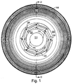
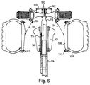
- FIGs. 1 to 6 An embodiment of the invention is illustrated in Figs. 1 to 6.
- the Figures illustrate the apparatus 100 in combination with a wheel 102, consisting of a hub 104 and a rim 106 on which a pneumatic tyre 108 is mounted, the wheel hub 104 being mounted in a conventional manner on an axle 110 by way of bearings 112.
- the axle 110 incorporates a hollow chamber 114 in which a hollow support member 115 is telescopically movable.
- a hollow rod member 116 forming part of the axle 110 extends coaxially with the chamber 114 and support member 115 towards the apparatus 100.
- a valve for emitting compressed air or other hydraulic or pneumatic fluid is arranged in the distal end of the rod member 116. The valve is connected in any convenient manner to an existing pneumatic or hydraulic system already incorporated within the aircraft.
- An upper housing 118 is rotatably mounted on the support member 115 above the wheel rim 106.
- the upper housing 118 is connected to the wheel 102 in that rotation of one about the axle 110 will cause rotation of the other.
- An upper reel 120 is also rotatably mounted with respect to the support member 115 and a braking member 122 is located on the side of the upper reel 120 remote from the upper housing 118.
- the braking member 122 is axially moveable with respect to the support member 115 but not rotatable with respect thereto.
- the upper housing 118 contains an interior chamber 124 which is in communication with a compressed air source (not shown) via the valve in the rod member 116.
- a plurality of air vents 126 are provided and a rotatably mounted fan arm 128 is associated with each air vent 126.
- the rotary mounting of each fan arm 128 is provided by means of a vertically extending axle 130 located adjacent the respective air vent 126 and about which the respective fan arm 128 is freely rotatable.
- tension cables 134 extend from the interior wall of the reel rim 106, to the upper reel 120, passing through the lower reel 132 and the distal ends of a plurality of the fan arms 128. The purpose of this arrangement will be described below.
- the fan arms 128 are generally angled or curved as shown in Fig. 1 so that, in the retracted position, they can overlap with one another and generally follow the shape of the upper housing 118. This minimises any drag effect during take-off.
- Each fan arm 128 consists of a plurality of substantially planar fan members 136 lying generally tangentially to the upper housing 118. These fan members 136 are illustrated most clearly in Fig. 4.
- the fan arms 128 also incorporate sail members 140 which extend generally perpendicular to the longitudinal axis of the apparatus 100 in the fully extended position.
- Figs. 1 and 2 illustrate the apparatus 100 in its fully retracted position.
- the support member 115 is fully retracted and the fan arms 128 are nested closely about the upper housing 118.
- the support member 115 is biased into this retracted position by means of, for example, a compression spring 138 located inside the axle 110.
- the compressed air entering the interior chamber 124 is allowed to exit via the air vents 126 which are arranged around the circumference of the interior chamber 124.
- the air vents 126 direct the compressed air onto the fan members 136 of the fan arms 128. This causes the fan arms 128 to rotate about the vertical axles 130 and move into the fully extended position illustrated in Figs. 4 and 5. In this fully extended position, continued expulsion of compressed air through the air vents 126 causes the compressed air to impinge upon the fan members 136 and this in turn causes the fan arms 128 to rotate thus causing rotation of the upper housing 118 and thereby causing rotation of the wheel 102.
- the sail members 140 encourage the compressed airstream to impinge upon the fan members 136 without becoming diverted.
- the compressed air supply is cut off.
- a throttle valve (not shown) in the hollow chamber 114 ensures that the apparatus 100 retracts relatively slowly to allow time for the fan arms 128 to return to their retracted positions before the upper housing 118 returns to its own retracted position.
- the cutting off of the compressed air supply means that the braking member 122 is no longer maintained spaced apart from the upper reel 120.
- the braking member 122 therefore comes into fictional contact with the rotating upper reel 120 and slows the rotation thereof.
- the tension cables 134 which are fixedly connected to the circumference of the upper reel 120, are therefore effectively wound onto the upper reel.
- the purpose of the lower reel 132 is to take up any slack in the tension cables 134 during the extension and retraction of the fan arms 128. Ideally, the lower reel 132 is kept under the action of biassing means so as to allow equilibrium to be maintained as far as possible without any slack being available.
- the apparatus 100 is also retracting in the axial direction of the wheel axle 110.
- the action of the throttle valve can be selected to ensure that the fan arms 128 do not come into contact with either the tyre 108 or the wheel rim 106.
- the wheel rim 106 or, indeed, the pneumatic tyre 108 can incorporate relatively small wind catching members 142 which are designed to encourage the wheel 102 to rotate in a direction opposite to that required for landing. This feature is utilised during the extension of the apparatus 100 in order to allow the tension in the tension cables 134 to be relaxed as the fan arms 128 are moving from their retracted position to their extended position. Thereafter, the effect of the fan arms 128 will override any effect of the wind catching members 142.
- a compressed air chamber or passageway 150 is provided. Looking firstly at Figs. 7 and 8, the chamber is bounded on one side by an upper cover 152 and by a lower passageway 154 on the other. At the radial extremes of the compressed air chamber 150, vents 156 are provided through which the compressed air introduced into the chamber 150 can escape. These vents 156 are arranged such that a tangential element of force is created, thereby ensuring that the wheel is rotated as compressed air passes through the vents 156. Arrangements different from that shown in Fig. 8 are, of course, possible and equally effective.
- the lower passageways 154 illustrated in Fig. 8 are arranged to pass through the wheel rim into the pneumatic tyre cavity before emerging again on the side of the tyre remote from the cover 152. This is done to avoid interference with the braking system. It also reduces the risk of an imbalance of the wheel occurring.
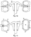
- FIG. 9 is a plan view of the air chamber illustrated on the left hand side of Fig. 10.
- compressed air is introduced to the chamber 150 via the axle.
- the compressed air passes along the radial passages 158 and then along the generally tangential passages 160 before exiting to atmosphere.
- the tangential arrangement of the passages 160 causes the wheel to which the chamber 150 is attached to rotate as compressed air is expelled.
- the chamber 150 described above is used in conjunction with a wheel having two adjacent tyres attached to a single wheel rim.
- the chamber 150 can be arranged so that the generally tangential passages 160 open in the area immediately between the two tyres. This reduces the risk of the passages 160 becoming inadvertently blocked by foreign matter, although care must be taken to ensure that the passages 160 do not extend radially to such a extent that they may become damaged during landing.
- FIG. 10 A similar but alternative arrangement is illustrated on the right hand side of Fig. 10. The only difference between this arrangement and that described above is the fact that the passages 162 extend substantially radially with respect to the wheel rim and incorporate tangential vents 164 at their distal ends. Again, the vents are effectively shielded from damage by the dual tyres and are positioned sufficiently near to the axle to avoid damage on landing.
- Fig. 11 illustrates two further variations on the same theme.
- the radially outward area of the chamber 150 is essentially incorporated into the tyre.
- the tyre 170 is mounted on a single wheel rim but incorporates two separate tubes 172, 174.
- the walls of the tubes 172, 174 also form the walls of the radial passage 176 which is located between the tubes 172, 174.
- a tangential vent 178 is arranged in the end of the passage 176.
- the outer wall of the tyre can incorporate passages which will create the desired effect.
- a tyre 180 is mounted on a wheel rim.
- the tyre 180 has a passage 182 moulded into the outer wall thereof which is in communication with the chamber 150 via a connection in the wheel rim.
- vents 184 are arranged which allow compressed air travelling down the passage 182 to escape to atmosphere.
- the vents 184 are arranged so as to produce a tangential element of flow in order to ensure that the passage of air therethrough creates a rotational movement of the wheel.
- the passage 182 is kept completely separate from the tyre proper; ie there is a substantial dividing wall between the tyre cavity 186 and the passage 182.
- the vents 184 can also be protected by means of shields (not shown) to prevent damage thereto on landing.
Landscapes
- Engineering & Computer Science (AREA)
- Mechanical Engineering (AREA)
- Aviation & Aerospace Engineering (AREA)
- Testing Of Balance (AREA)
- Tires In General (AREA)
- Electrophotography Configuration And Component (AREA)
- Friction Gearing (AREA)
- Braking Arrangements (AREA)
- Pulleys (AREA)
- Turbine Rotor Nozzle Sealing (AREA)
- Forklifts And Lifting Vehicles (AREA)
- Auxiliary Devices For And Details Of Packaging Control (AREA)
- Replacement Of Web Rolls (AREA)
- Devices For Checking Fares Or Tickets At Control Points (AREA)
- Toys (AREA)
- Wind Motors (AREA)
- Recording Measured Values (AREA)
- Jet Pumps And Other Pumps (AREA)
- Handcart (AREA)
- Transmission Devices (AREA)
- Motorcycle And Bicycle Frame (AREA)
Applications Claiming Priority (3)
| Application Number | Priority Date | Filing Date | Title |
|---|---|---|---|
| GB9523446 | 1995-11-15 | ||
| GB9523446A GB2307216A (en) | 1995-11-15 | 1995-11-15 | Apparatus for rotating an aircraft wheel prior to landing |
| EP96938347A EP0861189B1 (de) | 1995-11-15 | 1996-11-14 | Rotationshilfe für ein flugzeugrad |
Related Parent Applications (1)
| Application Number | Title | Priority Date | Filing Date |
|---|---|---|---|
| EP96938347A Division EP0861189B1 (de) | 1995-11-15 | 1996-11-14 | Rotationshilfe für ein flugzeugrad |
Publications (3)
| Publication Number | Publication Date |
|---|---|
| EP0934875A2 true EP0934875A2 (de) | 1999-08-11 |
| EP0934875A3 EP0934875A3 (de) | 1999-12-08 |
| EP0934875B1 EP0934875B1 (de) | 2002-08-14 |
Family
ID=10783985
Family Applications (2)
| Application Number | Title | Priority Date | Filing Date |
|---|---|---|---|
| EP96938347A Expired - Lifetime EP0861189B1 (de) | 1995-11-15 | 1996-11-14 | Rotationshilfe für ein flugzeugrad |
| EP99106512A Expired - Lifetime EP0934875B1 (de) | 1995-11-15 | 1996-11-14 | Rotationshilfe für ein Flugzeugrad |
Family Applications Before (1)
| Application Number | Title | Priority Date | Filing Date |
|---|---|---|---|
| EP96938347A Expired - Lifetime EP0861189B1 (de) | 1995-11-15 | 1996-11-14 | Rotationshilfe für ein flugzeugrad |
Country Status (10)
| Country | Link |
|---|---|
| US (1) | US6086017A (de) |
| EP (2) | EP0861189B1 (de) |
| AT (2) | ATE195473T1 (de) |
| AU (1) | AU7580396A (de) |
| DE (2) | DE69623056T2 (de) |
| DK (2) | DK0934875T3 (de) |
| ES (2) | ES2153131T3 (de) |
| GB (1) | GB2307216A (de) |
| PT (2) | PT934875E (de) |
| WO (1) | WO1997018127A1 (de) |
Cited By (1)
| Publication number | Priority date | Publication date | Assignee | Title |
|---|---|---|---|---|
| GB2356839A (en) * | 1999-11-03 | 2001-06-06 | Stanley Neil Whincup | Motor used to rotate an aircraft wheel prior to landing |
Families Citing this family (8)
| Publication number | Priority date | Publication date | Assignee | Title |
|---|---|---|---|---|
| US6450448B1 (en) * | 2001-08-17 | 2002-09-17 | Toshimi Suzuki | Airplane wheel unit |
| GB0129300D0 (en) * | 2001-12-07 | 2002-01-23 | Bae Systems Plc | Method of landing an aircraft and apparatus therefor |
| CA2508642A1 (en) * | 2005-06-09 | 2006-12-09 | Bela Bill Szoke | Airplane tire saver by protrusion airfoils |
| US8991752B2 (en) | 2011-11-07 | 2015-03-31 | Aerospin Corporation | Apparatus for pre-rotating aircraft tires |
| US20140048648A1 (en) * | 2012-08-17 | 2014-02-20 | Winter Karl | Free Spinning Wheel for Airplanes |
| MA35579B1 (fr) * | 2013-04-03 | 2014-11-01 | Aicha Farid | Système de contrôle de mise en rotation des roues avions à géométrie variable. |
| US11260967B1 (en) * | 2017-12-11 | 2022-03-01 | James Robert Davis | No/low skid device |
| US12473081B2 (en) | 2023-03-16 | 2025-11-18 | James Hooey | Aircraft wheel rotating device |
Citations (5)
| Publication number | Priority date | Publication date | Assignee | Title |
|---|---|---|---|---|
| FR912891A (fr) | 1945-03-07 | 1946-08-22 | Lanceur de roues d'atterrissage | |
| US2414849A (en) | 1944-12-08 | 1947-01-28 | Robert H Beazley | Aircraft wheel spinner and control |
| US2666604A (en) | 1952-01-14 | 1954-01-19 | Albert P Davis | Retractable wind scoop |
| US4385739A (en) | 1980-04-28 | 1983-05-31 | Soderberg John V | System for enhancing airborne safety of airborne vehicles as well as reducing tire wear thereof |
| US4732350A (en) | 1985-11-07 | 1988-03-22 | Lamont John S | Aircraft wheel rotation apparatus |
Family Cites Families (17)
| Publication number | Priority date | Publication date | Assignee | Title |
|---|---|---|---|---|
| US2435459A (en) * | 1943-02-19 | 1948-02-03 | William L Oden | Airplane landing gear |
| US2386301A (en) * | 1943-08-14 | 1945-10-09 | Duke Earl Hamilton | Mechanism for accelerating the wheels of the landing gear of an airplane |
| US2412406A (en) * | 1944-07-10 | 1946-12-10 | Kerezi Joseph | Aircraft landing wheel |
| GB588959A (en) * | 1944-08-11 | 1947-06-06 | Wingfoot Corp | Prerotation airplane tire and method of making it |
| GB584638A (en) * | 1945-01-15 | 1947-01-20 | John Foster Kendrick | Aeroplane landing gear |
| GB603804A (en) * | 1945-10-30 | 1948-06-23 | Lyndon White Manheim Sr | Wheel mountings for aircraft |
| US3026069A (en) * | 1960-04-12 | 1962-03-20 | Leparis D Young | Wheel rotating device for airplanes |
| US3741503A (en) * | 1972-04-10 | 1973-06-26 | H Cabeza | Aircraft landing gear |
| US3866860A (en) * | 1973-09-24 | 1975-02-18 | Sr John M Opitz | Airplane wheel rotator |
| DE3241908A1 (de) * | 1982-11-12 | 1984-05-17 | Manfred Dipl.-Ing. Hübbers (FH), 4450 Lingen | Fahrwerk fuer ein flugzeug |
| DE3420507A1 (de) * | 1984-06-01 | 1985-12-05 | Joachim Dipl.-Ing. 7900 Ulm Nedtwig | Verfahren zur vermeidung von differenzgeschwindigkeiten zwischen der landebahn und reifen von flugzeugen beim landeanflug |
| DE3504675A1 (de) * | 1985-02-12 | 1986-04-17 | Bernhard Ing.(grad.) 7536 Ispringen Reichle | Antriebsklappen fuer flugzeugreifen |
| GB2256402B (en) * | 1991-06-05 | 1995-01-25 | Kevin Mchale | Aircraft undercarriages |
| US5213285A (en) * | 1992-04-10 | 1993-05-25 | Stanko John J | Rotating aircraft tire/landing gear apparatus |
| US5251848A (en) * | 1992-05-14 | 1993-10-12 | The United States Of America As Represented By The Secretary Of The Navy | Space shuttle wheel acceleration system |
| DE4235815C2 (de) * | 1992-10-23 | 1995-01-05 | Deutsche Aerospace Airbus | Anordnung zur Steuerung der Antriebs- und Kühlfunktionen für ein Flugzeugfahrwerk |
| US5417387A (en) * | 1994-02-18 | 1995-05-23 | Jennings; Blake | Aircraft landing wheel rotator |
-
1995
- 1995-11-15 GB GB9523446A patent/GB2307216A/en not_active Withdrawn
-
1996
- 1996-11-14 WO PCT/GB1996/002791 patent/WO1997018127A1/en not_active Ceased
- 1996-11-14 DK DK99106512T patent/DK0934875T3/da active
- 1996-11-14 EP EP96938347A patent/EP0861189B1/de not_active Expired - Lifetime
- 1996-11-14 ES ES96938347T patent/ES2153131T3/es not_active Expired - Lifetime
- 1996-11-14 ES ES99106512T patent/ES2184366T3/es not_active Expired - Lifetime
- 1996-11-14 DE DE69623056T patent/DE69623056T2/de not_active Expired - Fee Related
- 1996-11-14 AU AU75803/96A patent/AU7580396A/en not_active Abandoned
- 1996-11-14 US US09/068,580 patent/US6086017A/en not_active Expired - Fee Related
- 1996-11-14 DE DE69609856T patent/DE69609856T2/de not_active Expired - Fee Related
- 1996-11-14 PT PT99106512T patent/PT934875E/pt unknown
- 1996-11-14 AT AT96938347T patent/ATE195473T1/de not_active IP Right Cessation
- 1996-11-14 AT AT99106512T patent/ATE222197T1/de not_active IP Right Cessation
- 1996-11-14 DK DK96938347T patent/DK0861189T3/da active
- 1996-11-14 PT PT96938347T patent/PT861189E/pt unknown
- 1996-11-14 EP EP99106512A patent/EP0934875B1/de not_active Expired - Lifetime
Patent Citations (5)
| Publication number | Priority date | Publication date | Assignee | Title |
|---|---|---|---|---|
| US2414849A (en) | 1944-12-08 | 1947-01-28 | Robert H Beazley | Aircraft wheel spinner and control |
| FR912891A (fr) | 1945-03-07 | 1946-08-22 | Lanceur de roues d'atterrissage | |
| US2666604A (en) | 1952-01-14 | 1954-01-19 | Albert P Davis | Retractable wind scoop |
| US4385739A (en) | 1980-04-28 | 1983-05-31 | Soderberg John V | System for enhancing airborne safety of airborne vehicles as well as reducing tire wear thereof |
| US4732350A (en) | 1985-11-07 | 1988-03-22 | Lamont John S | Aircraft wheel rotation apparatus |
Cited By (1)
| Publication number | Priority date | Publication date | Assignee | Title |
|---|---|---|---|---|
| GB2356839A (en) * | 1999-11-03 | 2001-06-06 | Stanley Neil Whincup | Motor used to rotate an aircraft wheel prior to landing |
Also Published As
| Publication number | Publication date |
|---|---|
| EP0861189A1 (de) | 1998-09-02 |
| EP0861189B1 (de) | 2000-08-16 |
| US6086017A (en) | 2000-07-11 |
| WO1997018127A1 (en) | 1997-05-22 |
| DE69609856T2 (de) | 2001-04-12 |
| EP0934875B1 (de) | 2002-08-14 |
| ATE195473T1 (de) | 2000-09-15 |
| DK0861189T3 (da) | 2000-12-18 |
| AU7580396A (en) | 1997-06-05 |
| EP0934875A3 (de) | 1999-12-08 |
| DE69623056D1 (de) | 2002-09-19 |
| DE69623056T2 (de) | 2003-04-17 |
| GB2307216A (en) | 1997-05-21 |
| GB9523446D0 (en) | 1996-01-17 |
| DK0934875T3 (da) | 2002-12-09 |
| ATE222197T1 (de) | 2002-08-15 |
| PT934875E (pt) | 2002-11-29 |
| ES2184366T3 (es) | 2003-04-01 |
| PT861189E (pt) | 2001-02-28 |
| DE69609856D1 (de) | 2000-09-21 |
| ES2153131T3 (es) | 2001-02-16 |
Similar Documents
| Publication | Publication Date | Title |
|---|---|---|
| EP0934875A2 (de) | Rotationshilfe für ein Flugzeugrad | |
| JP6742114B2 (ja) | 逆推力装置及び方法 | |
| US4732350A (en) | Aircraft wheel rotation apparatus | |
| US8636248B2 (en) | Retracting tailwheel assembly and fin | |
| CN102202967B (zh) | 发动机防碎片装置 | |
| US5259431A (en) | Aircraft tire with sidewall vanes | |
| CA2274336A1 (en) | Expandable belt and tread drum | |
| US5417387A (en) | Aircraft landing wheel rotator | |
| US4491288A (en) | Aircraft landing wheel rotating means | |
| EP3892080B1 (de) | Fadenschneider | |
| US6983911B1 (en) | Aviation tire | |
| US4102423A (en) | Ground traction devices | |
| US5746393A (en) | Aircraft wheel rotating apparatus | |
| US2424941A (en) | Wheel gear | |
| US20150021435A1 (en) | Apparatus for causing an aircraft wheel to rotate | |
| US2884633A (en) | Vertical take off and landing apparatus for use with aircraft | |
| US2412033A (en) | Tire prerotating device | |
| US2372207A (en) | Airplane landing gear | |
| DE2109563A1 (de) | Antrieb für ein Flugzeug-Fahrwerkrad | |
| WO1992015483A1 (en) | Aircraft wheel prerotation apparatus | |
| US6390415B1 (en) | Wheel rotation device | |
| US5810276A (en) | Turbine head assembly with inlet valve driven by a forward positioned actuation assembly | |
| GB2256402A (en) | Aircraft undercarriages with means to rotate the wheels. | |
| GB2242401A (en) | Aircraft wheel and means to reduce tyre wear on landing | |
| SE506091C2 (sv) | Förfarande och anordning vid stamkvistning |
Legal Events
| Date | Code | Title | Description |
|---|---|---|---|
| PUAI | Public reference made under article 153(3) epc to a published international application that has entered the european phase |
Free format text: ORIGINAL CODE: 0009012 |
|
| 17P | Request for examination filed |
Effective date: 19990429 |
|
| AC | Divisional application: reference to earlier application |
Ref document number: 861189 Country of ref document: EP |
|
| AK | Designated contracting states |
Kind code of ref document: A2 Designated state(s): AT BE CH DE DK ES FI FR GB GR IE IT LI LU MC NL PT SE |
|
| PUAL | Search report despatched |
Free format text: ORIGINAL CODE: 0009013 |
|
| AK | Designated contracting states |
Kind code of ref document: A3 Designated state(s): AT BE CH DE DK ES FI FR GB GR IE IT LI LU MC NL PT SE |
|
| 17Q | First examination report despatched |
Effective date: 20001017 |
|
| GRAG | Despatch of communication of intention to grant |
Free format text: ORIGINAL CODE: EPIDOS AGRA |
|
| GRAG | Despatch of communication of intention to grant |
Free format text: ORIGINAL CODE: EPIDOS AGRA |
|
| GRAH | Despatch of communication of intention to grant a patent |
Free format text: ORIGINAL CODE: EPIDOS IGRA |
|
| GRAH | Despatch of communication of intention to grant a patent |
Free format text: ORIGINAL CODE: EPIDOS IGRA |
|
| GRAA | (expected) grant |
Free format text: ORIGINAL CODE: 0009210 |
|
| AC | Divisional application: reference to earlier application |
Ref document number: 861189 Country of ref document: EP |
|
| AK | Designated contracting states |
Kind code of ref document: B1 Designated state(s): AT BE CH DE DK ES FI FR GB GR IE IT LI LU MC NL PT SE |
|
| PG25 | Lapsed in a contracting state [announced via postgrant information from national office to epo] |
Ref country code: GR Free format text: LAPSE BECAUSE OF FAILURE TO SUBMIT A TRANSLATION OF THE DESCRIPTION OR TO PAY THE FEE WITHIN THE PRESCRIBED TIME-LIMIT Effective date: 20020814 |
|
| REF | Corresponds to: |
Ref document number: 222197 Country of ref document: AT Date of ref document: 20020815 Kind code of ref document: T |
|
| REG | Reference to a national code |
Ref country code: GB Ref legal event code: FG4D |
|
| REG | Reference to a national code |
Ref country code: CH Ref legal event code: EP |
|
| REG | Reference to a national code |
Ref country code: IE Ref legal event code: FG4D |
|
| REF | Corresponds to: |
Ref document number: 69623056 Country of ref document: DE Date of ref document: 20020919 |
|
| ET | Fr: translation filed | ||
| PG25 | Lapsed in a contracting state [announced via postgrant information from national office to epo] |
Ref country code: LU Free format text: LAPSE BECAUSE OF NON-PAYMENT OF DUE FEES Effective date: 20021114 Ref country code: IE Free format text: LAPSE BECAUSE OF NON-PAYMENT OF DUE FEES Effective date: 20021114 Ref country code: GB Free format text: LAPSE BECAUSE OF NON-PAYMENT OF DUE FEES Effective date: 20021114 Ref country code: FI Free format text: LAPSE BECAUSE OF NON-PAYMENT OF DUE FEES Effective date: 20021114 Ref country code: AT Free format text: LAPSE BECAUSE OF NON-PAYMENT OF DUE FEES Effective date: 20021114 |
|
| PG25 | Lapsed in a contracting state [announced via postgrant information from national office to epo] |
Ref country code: SE Free format text: LAPSE BECAUSE OF NON-PAYMENT OF DUE FEES Effective date: 20021115 Ref country code: ES Free format text: LAPSE BECAUSE OF NON-PAYMENT OF DUE FEES Effective date: 20021115 |
|
| REG | Reference to a national code |
Ref country code: PT Ref legal event code: SC4A Free format text: AVAILABILITY OF NATIONAL TRANSLATION Effective date: 20020829 |
|
| PG25 | Lapsed in a contracting state [announced via postgrant information from national office to epo] |
Ref country code: LI Free format text: LAPSE BECAUSE OF NON-PAYMENT OF DUE FEES Effective date: 20021130 Ref country code: CH Free format text: LAPSE BECAUSE OF NON-PAYMENT OF DUE FEES Effective date: 20021130 Ref country code: BE Free format text: LAPSE BECAUSE OF NON-PAYMENT OF DUE FEES Effective date: 20021130 |
|
| REG | Reference to a national code |
Ref country code: DK Ref legal event code: T3 |
|
| PG25 | Lapsed in a contracting state [announced via postgrant information from national office to epo] |
Ref country code: DK Free format text: LAPSE BECAUSE OF NON-PAYMENT OF DUE FEES Effective date: 20021231 |
|
| REG | Reference to a national code |
Ref country code: ES Ref legal event code: FG2A Ref document number: 2184366 Country of ref document: ES Kind code of ref document: T3 |
|
| REG | Reference to a national code |
Ref country code: CH Ref legal event code: NV Representative=s name: RITSCHER & PARTNER AG PATENTANWAELTE |
|
| BERE | Be: lapsed |
Owner name: *AL-THANI HAMAD ALI JASSIM Effective date: 20021130 |
|
| PG25 | Lapsed in a contracting state [announced via postgrant information from national office to epo] |
Ref country code: NL Free format text: LAPSE BECAUSE OF NON-PAYMENT OF DUE FEES Effective date: 20030601 Ref country code: MC Free format text: LAPSE BECAUSE OF NON-PAYMENT OF DUE FEES Effective date: 20030601 |
|
| PG25 | Lapsed in a contracting state [announced via postgrant information from national office to epo] |
Ref country code: DE Free format text: LAPSE BECAUSE OF NON-PAYMENT OF DUE FEES Effective date: 20030603 |
|
| PLBE | No opposition filed within time limit |
Free format text: ORIGINAL CODE: 0009261 |
|
| STAA | Information on the status of an ep patent application or granted ep patent |
Free format text: STATUS: NO OPPOSITION FILED WITHIN TIME LIMIT |
|
| EUG | Se: european patent has lapsed | ||
| GBPC | Gb: european patent ceased through non-payment of renewal fee | ||
| REG | Reference to a national code |
Ref country code: DK Ref legal event code: EBP |
|
| REG | Reference to a national code |
Ref country code: CH Ref legal event code: PL |
|
| PG25 | Lapsed in a contracting state [announced via postgrant information from national office to epo] |
Ref country code: FR Free format text: LAPSE BECAUSE OF NON-PAYMENT OF DUE FEES Effective date: 20030731 |
|
| NLV4 | Nl: lapsed or anulled due to non-payment of the annual fee |
Effective date: 20030601 |
|
| 26N | No opposition filed |
Effective date: 20030515 |
|
| REG | Reference to a national code |
Ref country code: IE Ref legal event code: MM4A |
|
| REG | Reference to a national code |
Ref country code: FR Ref legal event code: ST |
|
| REG | Reference to a national code |
Ref country code: ES Ref legal event code: FD2A Effective date: 20031213 |
|
| PG25 | Lapsed in a contracting state [announced via postgrant information from national office to epo] |
Ref country code: PT Free format text: LAPSE BECAUSE OF NON-PAYMENT OF DUE FEES Effective date: 20040531 |
|
| REG | Reference to a national code |
Ref country code: PT Ref legal event code: MM4A Free format text: LAPSE DUE TO NON-PAYMENT OF FEES Effective date: 20040531 |
|
| PG25 | Lapsed in a contracting state [announced via postgrant information from national office to epo] |
Ref country code: IT Free format text: LAPSE BECAUSE OF NON-PAYMENT OF DUE FEES Effective date: 20051114 |
|
| PG25 | Lapsed in a contracting state [announced via postgrant information from national office to epo] |
Ref country code: PT Free format text: LAPSE BECAUSE OF NON-PAYMENT OF DUE FEES Effective date: 20021114 |