EP0934887A1 - Verschlussvorrichtung für Getränkedose, insbesondere für kohlensäurehaltige Getränke - Google Patents
Verschlussvorrichtung für Getränkedose, insbesondere für kohlensäurehaltige Getränke Download PDFInfo
- Publication number
- EP0934887A1 EP0934887A1 EP99400238A EP99400238A EP0934887A1 EP 0934887 A1 EP0934887 A1 EP 0934887A1 EP 99400238 A EP99400238 A EP 99400238A EP 99400238 A EP99400238 A EP 99400238A EP 0934887 A1 EP0934887 A1 EP 0934887A1
- Authority
- EP
- European Patent Office
- Prior art keywords
- box
- skirt
- clamping ring
- rim
- bearing surface
- Prior art date
- Legal status (The legal status is an assumption and is not a legal conclusion. Google has not performed a legal analysis and makes no representation as to the accuracy of the status listed.)
- Granted
Links
- 235000013361 beverage Nutrition 0.000 title claims abstract description 12
- 235000014171 carbonated beverage Nutrition 0.000 title description 2
- 230000002093 peripheral effect Effects 0.000 claims description 19
- 230000000694 effects Effects 0.000 claims description 7
- 239000000463 material Substances 0.000 description 3
- 240000008042 Zea mays Species 0.000 description 2
- 230000000903 blocking effect Effects 0.000 description 2
- 238000002788 crimping Methods 0.000 description 2
- 230000004308 accommodation Effects 0.000 description 1
- XAGFODPZIPBFFR-UHFFFAOYSA-N aluminium Chemical compound [Al] XAGFODPZIPBFFR-UHFFFAOYSA-N 0.000 description 1
- 229910052782 aluminium Inorganic materials 0.000 description 1
- 210000000481 breast Anatomy 0.000 description 1
- 238000006073 displacement reaction Methods 0.000 description 1
- 230000035622 drinking Effects 0.000 description 1
- 229920001903 high density polyethylene Polymers 0.000 description 1
- 239000004700 high-density polyethylene Substances 0.000 description 1
- 230000003100 immobilizing effect Effects 0.000 description 1
- 238000009434 installation Methods 0.000 description 1
- 239000007788 liquid Substances 0.000 description 1
- 210000002445 nipple Anatomy 0.000 description 1
- 230000000750 progressive effect Effects 0.000 description 1
- 238000007789 sealing Methods 0.000 description 1
Images


Classifications
-
- B—PERFORMING OPERATIONS; TRANSPORTING
- B65—CONVEYING; PACKING; STORING; HANDLING THIN OR FILAMENTARY MATERIAL
- B65D—CONTAINERS FOR STORAGE OR TRANSPORT OF ARTICLES OR MATERIALS, e.g. BAGS, BARRELS, BOTTLES, BOXES, CANS, CARTONS, CRATES, DRUMS, JARS, TANKS, HOPPERS, FORWARDING CONTAINERS; ACCESSORIES, CLOSURES, OR FITTINGS THEREFOR; PACKAGING ELEMENTS; PACKAGES
- B65D51/00—Closures not otherwise provided for
- B65D51/18—Arrangements of closures with protective outer cap-like covers or of two or more co-operating closures
- B65D51/20—Caps, lids, or covers co-operating with an inner closure arranged to be opened by piercing, cutting, or tearing
-
- B—PERFORMING OPERATIONS; TRANSPORTING
- B65—CONVEYING; PACKING; STORING; HANDLING THIN OR FILAMENTARY MATERIAL
- B65D—CONTAINERS FOR STORAGE OR TRANSPORT OF ARTICLES OR MATERIALS, e.g. BAGS, BARRELS, BOTTLES, BOXES, CANS, CARTONS, CRATES, DRUMS, JARS, TANKS, HOPPERS, FORWARDING CONTAINERS; ACCESSORIES, CLOSURES, OR FITTINGS THEREFOR; PACKAGING ELEMENTS; PACKAGES
- B65D47/00—Closures with filling and discharging, or with discharging, devices
- B65D47/04—Closures with discharging devices other than pumps
- B65D47/06—Closures with discharging devices other than pumps with pouring spouts or tubes; with discharge nozzles or passages
- B65D47/12—Closures with discharging devices other than pumps with pouring spouts or tubes; with discharge nozzles or passages having removable closures
- B65D47/14—Closures with discharging devices other than pumps with pouring spouts or tubes; with discharge nozzles or passages having removable closures and closure-retaining means
- B65D47/141—Closures with discharging devices other than pumps with pouring spouts or tubes; with discharge nozzles or passages having removable closures and closure-retaining means for stoppers
-
- B—PERFORMING OPERATIONS; TRANSPORTING
- B65—CONVEYING; PACKING; STORING; HANDLING THIN OR FILAMENTARY MATERIAL
- B65D—CONTAINERS FOR STORAGE OR TRANSPORT OF ARTICLES OR MATERIALS, e.g. BAGS, BARRELS, BOTTLES, BOXES, CANS, CARTONS, CRATES, DRUMS, JARS, TANKS, HOPPERS, FORWARDING CONTAINERS; ACCESSORIES, CLOSURES, OR FITTINGS THEREFOR; PACKAGING ELEMENTS; PACKAGES
- B65D2251/00—Details relating to container closures
- B65D2251/0003—Two or more closures
- B65D2251/0006—Upper closure
- B65D2251/0025—Upper closure of the 47-type
-
- B—PERFORMING OPERATIONS; TRANSPORTING
- B65—CONVEYING; PACKING; STORING; HANDLING THIN OR FILAMENTARY MATERIAL
- B65D—CONTAINERS FOR STORAGE OR TRANSPORT OF ARTICLES OR MATERIALS, e.g. BAGS, BARRELS, BOTTLES, BOXES, CANS, CARTONS, CRATES, DRUMS, JARS, TANKS, HOPPERS, FORWARDING CONTAINERS; ACCESSORIES, CLOSURES, OR FITTINGS THEREFOR; PACKAGING ELEMENTS; PACKAGES
- B65D2251/00—Details relating to container closures
- B65D2251/0003—Two or more closures
- B65D2251/0068—Lower closure
- B65D2251/0071—Lower closure of the 17-type
Definitions
- the present invention relates to a closure device for a box of drink, especially carbonated drink, of the type having a side wall cylindrical closed at its base by a bottom and at its upper part by a cover irremovable which is provided with an at least partially separable cover and a rim peripheral and which is connected, from its periphery, to the upper end of said side wall by a portion flared radially outwards.
- any user of such a beverage can in particular a can of which the cover is removed by tearing, which has not consumed all of its content, one day or another wished to close this box tightly to avoid loss of the liquid remaining due to the overturning of the box and / or to keep the drink all its properties and qualities.
- the object of the present invention therefore lies in the development of a device simple design, easily adaptable to a non-sealed beverage can reusable, ensuring a watertight closure of the box once its cover removed and which is also provided with means facilitating the consumption of the drink.
- the present invention provides a closure device which comprises the means (a) and (b) above and which is characterized in that said means of pressure include a concentric clamping ring with said peripheral skirt around the axis of symmetry of the box, said clamping ring having a first face inner consisting of at least one cylindrical surface eccentric with respect to said axis of symmetry and cooperating with a corresponding cylindrical surface defining a outer face of the peripheral skirt.
- the device according to the invention advantageously comprises blocking means to prevent any rotation of said cap relative to the box.
- These blocking means may simply include a protuberance arising on the upper element of the cap and extending below this element over a sufficient length to be able to penetrate the orifice which is formed in the cover of the box after removal of said removable cover.
- the skirt cap peripheral includes at least one additional annular housing axially and radially offset from the first housing and intended to receive the rim of a beverage can of different diameter than that of the can whose rim is intended to be received in the first accommodation.
- the peripheral skirt comprises at least one additional continuous bearing surface axially and radially offset from the first bearing surface and the ring clamping device has at least one additional inner face axially and radially offset from the first inner face and consisting of at least a cylindrical surface eccentric with respect to the axis of symmetry of the base and cooperating with a corresponding cylindrical surface defining another external face of the peripheral skirt.
- each inner face of the clamping ring is preferably constituted by several successive cylindrical surfaces which meet and eccentric each relative to the axis of symmetry of the box, these surfaces having the same length angular, which ensures rapid and uniform tightening.
- each bearing surface is preferably substantially parallel to the flared part of the box and arranged to be opposite this part flared.
- the upper element of the cap prefferably has a groove concentric in the vicinity of its periphery; the purpose of this groove is to remove rigidity to this upper element and therefore facilitate the installation of the device on the box.
- each housing has a bearing surface extending over its entire internal periphery and which, under the effect said pressure means, is applied against the inner face of the rim of the box ; this measure further improves, if necessary, the sealing of the device.
- this device can also advantageously include means attachment capable of coming to bear elastically on the side wall of the box.
- the device-drink can assembly can be easily attached to any available support such as bag or belt, making it very easy transport.
- attachment means preferably comprise a tab extending axially and integral with the clamping ring.
- the device according to the invention is intended to achieve the closure in particular of a beverage can as shown in Figure 1.
- This can is formed by a body metallic usually aluminum, which generally has a side wall 1 cylindrical, closed by a bottom 2 and by a slightly domed cover 3.
- This last is provided with a tear-off lid 4 of substantially circular shape initially closed, but which can easily be removed by lifting a tab 5 which acts as a lever for tearing said cover 4 and thus clearing an orifice for the flow of the beverage.
- the cover 3 is also provided, along its periphery, with a flange 6 protruding above said cover.
- This rim 6, which has an annular lip outer 7, results from the crimping of a peripheral zone of said cover 3 with the upper end of the side wall 1, this crimping operation having the effect to give the upper part of the side wall 1 the shape of a flared zone 8 radially outward from the periphery of the cover.
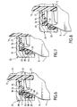
- the device according to the invention comprises, in a manner known per se, a cap 9 formed by an upper plate 10 and a peripheral skirt 11 and means pressure of said skirt against the box.
- the plate 10 is circular in shape and its diameter is substantially equal to that of the cover 3.
- a circular bore 12 positioned for come substantially opposite the orifice intended to be formed by removal of the cover 4.
- This bore 12 is extended at its periphery by a neck 13 extending vertically above the plate 10, the free edge of this neck being shaped rounded.
- this neck 13 is provided on its internal surface with a thread 14; the latter is intended to cooperate with a helical groove dug in the part cylindrical 15 of a plug 16 intended to be hermetically screwed into said neck 13.
- a protuberance 17 on its underside and shaped to engage in the orifice intended to be formed in the cover 3 by tearing the cover 4.
- the peripheral skirt 11 of the cap 9 has on the side of its internal face a first annular housing 18 shaped to receive the upper end (including the lip 7) of the rim 6 of the box and, axially below this housing 18, a first bearing surface 19 extending over the entire periphery of the skirt.
- the skirt comprises, also on the side of its face internal, an additional annular housing 20 located below the housing 18 in being offset axially and radially with respect to the latter; in addition, said skirt comprises, axially below the housing 20, an additional bearing surface 21 extending over the entire periphery of the internal face of the skirt.
- the additional housing 20 is also shaped to receive the upper end (including the lip 7) of the rim 6 of a box, the diameter of this last being greater than that of the box whose rim 6 is intended to be housed in housing 18.
- the internal face of the housing 18 intended to cooperate with the lip 7 of the rim 6, is connected to the first bearing surface 19 by a shoulder radial 22 able to be fitted under the lip 7; the same is true of the internal face of the housing 20 intended to cooperate with the lip 7, which is connected to the bearing surface 21 by a radial shoulder 23 also capable of being fitted under the lip 7 of the ledge 6.
- the cap 9 is made of an elastically deformable and compressible material, such as for example high density polyethylene.
- an elastically deformable and compressible material such as for example high density polyethylene.
- bearing surfaces 19, 21 are preferably substantially parallel, at least over part of their height, at the flared part 8 of the box and arranged to be in front of this flared part.
- the aforementioned pressure means include a clamping ring 25.
- This ring 25 has an upper wall 26 in the form of flat disc, provided with an opening 27 sized to allow free passage to the neck 13.
- This upper wall 26, which is intended to come to bear on the plate 10, is connected by its periphery to an annular side wall 28 concentric with the skirt 11 around the axis of symmetry A-A of the box.
- this annular wall 28 of the clamping ring has a first inner face 29 originating on the underside of the upper wall 26 and extending axially until it reaches a level slightly below the shoulder 22.
- the annular wall 28 also has a second inner face 30 offset axially and radially with respect to the first inner face 29, this second face 30 extending axially substantially up to the end lower of the support surface 21.
- the first inner face 29 is formed by several (three in the mode of embodiment shown in the drawings) successive cylindrical surfaces 31, 32, 33, of same angular length, each eccentric with respect to the axis of symmetry A-A. These cylindrical surfaces cooperate respectively with three cylindrical surfaces 34, 35, 36 corresponding defining a first external face of the skirt 11.
- the second inner face 30 is formed by several (for example three) successive cylindrical surfaces, of the same angular length, each eccentric with respect to the axis of symmetry A-A, these cylindrical surfaces cooperating respectively with three corresponding surfaces defining a second external face of the skirt 11; we will specify that these three cylindrical surfaces have respectively the same center as surfaces 31, 32, 33.
- a flexible tongue 37 connecting the part top of the plug 16 to the upper wall 26 of the clamping ring.
- the tongue 37 is fixed to the wall 26 by a stud 38 integral with the tongue, extending axially downwards and the free end of which lower ends with an enlarged part 39.
- This nipple is forced into a notch 40 having a narrowing at its Entrance.
- this enlarged part 39 can circulate in an enlarged area 41 of the groove 24 as shown in FIG. 5.
- the device according to the invention is finally completed by an elastic tab 42 extending axially and secured by its upper end to the side wall 28 of the clamping ring, this tab being intended to bear elastically against the side wall 1 of the box.
- the user After tearing of the cover 4 by lifting the tab 5, the user releases an opening in the cover 3 of the box, opening through which it consumes part of the drink contained in said box. To avoid everything spilling the remaining drink and preserving the quality and properties of this last, the user applies said device on the box.
- this device On the upper face (cover) 3 of this box, engages the protrusion 17 in the aforementioned opening in the cover, then apply to the device a slight force directed axially from top to bottom to bring, thanks to the elasticity of the skirt 11, the shoulder 22 to slide axially along the lip 7 until it come and fit under this lip.
- the rim 6 of this box will take place either in the upper housing 18 (small diameter box), or in the lower housing 20 (large diameter box).
- the user then communicates to the clamping ring 25 a rotational movement, movement which is not transmitted to the cap 9 since the latter is immobilized in rotation by the protrusion 17. Due to the rotational movement communicated to the ring 25, by the play of the eccentric cylindrical surfaces present on the internal faces side wall 28 of the ring and the external faces of the skirt 11, we then assist a progressive tightening which results in a pressure of said side wall 28 on the skirt 11, which has the effect of pressing the bearing surface 19 against the flared part of the box ; due to the elastic and compressible nature of the material constituting the skirt, this results in the desired seal between the inside of the box and the atmosphere outside.
- each housing 18, 20 may include a bearing surface 43, 44 positioned to be pressed, under the effect of the tightening produced by the ring, against the inner face of the rim 6, which contributes, if necessary, to achieve this seal.
- the box-closing device assembly resulting can then for example be stored in a refrigerator awaiting further use. It can still be hung by means of the tab 42 for example to a belt or a bag or a thong of a any equipment such as that of a hiker, a skier, etc ...
- the device can be easily separated from the box vacuum by rotation in opposite direction of the clamping ring, then axial traction upwards.
Landscapes
- Engineering & Computer Science (AREA)
- Mechanical Engineering (AREA)
- Closures For Containers (AREA)
- Non-Alcoholic Beverages (AREA)
- Devices For Dispensing Beverages (AREA)
- Filling Of Jars Or Cans And Processes For Cleaning And Sealing Jars (AREA)
- Basic Packing Technique (AREA)
Applications Claiming Priority (2)
| Application Number | Priority Date | Filing Date | Title |
|---|---|---|---|
| FR9801300 | 1998-02-04 | ||
| FR9801300A FR2774364B1 (fr) | 1998-02-04 | 1998-02-04 | Dispositif de fermeture pour une boite de boisson, notamment de boisson gazeuse |
Publications (2)
| Publication Number | Publication Date |
|---|---|
| EP0934887A1 true EP0934887A1 (de) | 1999-08-11 |
| EP0934887B1 EP0934887B1 (de) | 2002-08-28 |
Family
ID=9522591
Family Applications (1)
| Application Number | Title | Priority Date | Filing Date |
|---|---|---|---|
| EP99400238A Expired - Lifetime EP0934887B1 (de) | 1998-02-04 | 1999-02-03 | Verschlussvorrichtung für Getränkedose, insbesondere für kohlensäurehaltige Getränke |
Country Status (4)
| Country | Link |
|---|---|
| EP (1) | EP0934887B1 (de) |
| AT (1) | ATE222874T1 (de) |
| DE (1) | DE69902601D1 (de) |
| FR (1) | FR2774364B1 (de) |
Cited By (6)
| Publication number | Priority date | Publication date | Assignee | Title |
|---|---|---|---|---|
| WO2001092133A2 (en) | 2000-06-01 | 2001-12-06 | Jan Essebaggers | Carbonated beverage container with suction spout |
| GB2413791A (en) * | 2004-04-27 | 2005-11-09 | David Dennis Dunkley | Closure device for a beverage can |
| GB2457944A (en) * | 2008-02-29 | 2009-09-02 | Tullman Design Ltd | A cap fixture including a spout |
| US8469221B2 (en) | 2004-07-09 | 2013-06-25 | Ball Packaging Europe Gmbh | Floating multi-chambered insert for liquid containers |
| FR3027593A1 (fr) * | 2014-10-23 | 2016-04-29 | Soc Viaplast | Dispositif monobloc pour refermer hermetiquement les recipients metalliques appeles canettes apres ouverture par l'utilisateur |
| CN111994450A (zh) * | 2019-05-27 | 2020-11-27 | 农夫山泉(淳安茶园)饮料有限公司 | 易穿破的饮水机水桶的桶盖和饮水机水桶 |
Families Citing this family (2)
| Publication number | Priority date | Publication date | Assignee | Title |
|---|---|---|---|---|
| FR2814153A1 (fr) | 2000-09-15 | 2002-03-22 | Siid | Dispositif bec verseur / bouchon adaptable sur une canette |
| DE10258791B4 (de) | 2002-12-16 | 2007-03-22 | Ball Packaging Europe Gmbh | Flüssigkeitsbehälter-Einsatz mit zeitdeterminierter Positionierung in einer unter Gasdruck stehenden Flüssigkeit |
Citations (5)
| Publication number | Priority date | Publication date | Assignee | Title |
|---|---|---|---|---|
| EP0112306A2 (de) * | 1982-12-15 | 1984-06-27 | Sergio Tontarelli | Kappe zum zeitlichen hermetischen Verschluss von zylindrischen metallischen Büchsen mit zerreissbarer Öffnungslasche |
| US4579257A (en) * | 1983-06-25 | 1986-04-01 | Braendlein Manfred | Closure for beverage cans or the like |
| US5062552A (en) * | 1989-01-11 | 1991-11-05 | Walter Heubel | Spout for different size cans |
| US5176278A (en) * | 1992-01-31 | 1993-01-05 | Quarberg Craig D | Beverage can resealing device |
| FR2750111A1 (fr) * | 1996-06-25 | 1997-12-26 | Karol Genesi | Bouchon gobelet pour canette de boissons |
-
1998
- 1998-02-04 FR FR9801300A patent/FR2774364B1/fr not_active Expired - Fee Related
-
1999
- 1999-02-03 DE DE69902601T patent/DE69902601D1/de not_active Expired - Lifetime
- 1999-02-03 EP EP99400238A patent/EP0934887B1/de not_active Expired - Lifetime
- 1999-02-03 AT AT99400238T patent/ATE222874T1/de not_active IP Right Cessation
Patent Citations (5)
| Publication number | Priority date | Publication date | Assignee | Title |
|---|---|---|---|---|
| EP0112306A2 (de) * | 1982-12-15 | 1984-06-27 | Sergio Tontarelli | Kappe zum zeitlichen hermetischen Verschluss von zylindrischen metallischen Büchsen mit zerreissbarer Öffnungslasche |
| US4579257A (en) * | 1983-06-25 | 1986-04-01 | Braendlein Manfred | Closure for beverage cans or the like |
| US5062552A (en) * | 1989-01-11 | 1991-11-05 | Walter Heubel | Spout for different size cans |
| US5176278A (en) * | 1992-01-31 | 1993-01-05 | Quarberg Craig D | Beverage can resealing device |
| FR2750111A1 (fr) * | 1996-06-25 | 1997-12-26 | Karol Genesi | Bouchon gobelet pour canette de boissons |
Cited By (6)
| Publication number | Priority date | Publication date | Assignee | Title |
|---|---|---|---|---|
| WO2001092133A2 (en) | 2000-06-01 | 2001-12-06 | Jan Essebaggers | Carbonated beverage container with suction spout |
| GB2413791A (en) * | 2004-04-27 | 2005-11-09 | David Dennis Dunkley | Closure device for a beverage can |
| US8469221B2 (en) | 2004-07-09 | 2013-06-25 | Ball Packaging Europe Gmbh | Floating multi-chambered insert for liquid containers |
| GB2457944A (en) * | 2008-02-29 | 2009-09-02 | Tullman Design Ltd | A cap fixture including a spout |
| FR3027593A1 (fr) * | 2014-10-23 | 2016-04-29 | Soc Viaplast | Dispositif monobloc pour refermer hermetiquement les recipients metalliques appeles canettes apres ouverture par l'utilisateur |
| CN111994450A (zh) * | 2019-05-27 | 2020-11-27 | 农夫山泉(淳安茶园)饮料有限公司 | 易穿破的饮水机水桶的桶盖和饮水机水桶 |
Also Published As
| Publication number | Publication date |
|---|---|
| FR2774364B1 (fr) | 2000-04-14 |
| ATE222874T1 (de) | 2002-09-15 |
| EP0934887B1 (de) | 2002-08-28 |
| DE69902601D1 (de) | 2002-10-02 |
| FR2774364A1 (fr) | 1999-08-06 |
Similar Documents
| Publication | Publication Date | Title |
|---|---|---|
| EP0889846B1 (de) | Zapfhahn für flüssigkeiten | |
| EP0667301B1 (de) | Ausgabevorrichtung für Flüssigkeiten oder Pulver | |
| FR2617134A1 (fr) | Obturateur a embout verseur et bouchon doseur a bec verseur | |
| FR2569666A1 (fr) | Dispositif permettant de conserver, separes l'un de l'autre, au moins deux produits et d'effectuer leur melange ulterieurement, notamment au moment de l'utilisation | |
| LU86294A1 (fr) | Monture de tetine et ensemble a tetine | |
| CA2290672A1 (fr) | Capsule de fermeture pour boite metallique pour boissons | |
| FR2502591A1 (fr) | Assemblage de liaison pour systemes a deux composantes | |
| EP0934887B1 (de) | Verschlussvorrichtung für Getränkedose, insbesondere für kohlensäurehaltige Getränke | |
| FR2736620A1 (fr) | Element de fermeture pour boite de boisson | |
| FR2838715A1 (fr) | Dispositif de bouchage et recipient equipe d'un tel dispositif | |
| CA2094679A1 (fr) | Capsule distributrice pour produits liquides ou pateux | |
| FR2913677A1 (fr) | Decapsuleur pour capsule de bouchage du col d'une bouteille. | |
| EP2146908A1 (de) | Behälterkappe mit zusätzlicher aufnahmekapazität | |
| EP0659147A1 (de) | Trinkbecher zum anbringen an einen getränkebehälter | |
| FR2516899A1 (fr) | Dispositif pour prelever des substances pateuses dans des recipients remplis avec un gaz propulseur | |
| FR2712261A1 (fr) | Dispositif pour boire une boisson en boîte. | |
| FR2735754A1 (fr) | Pot, notamment pour le conditionnement de produits alimentaires | |
| FR2748260A1 (fr) | Dispositif de bouchage inviolable pour un recipient tel qu'en particulier une bouteille ou un flacon | |
| FR2593145A1 (fr) | Recipient comprenant un col et un capuchon amovible. | |
| FR2572749A1 (fr) | Dispositif pour distribuer une dose d'un produit liquide dans un reservoir de liquide, en particulier un reservoir de chasse d'eau | |
| FR2953814A1 (fr) | Recipient equipe d'un bouchon d'ouverture et de refermeture etanche | |
| FR2733739A1 (fr) | Bouchon adaptable pour canette | |
| EP0742776A1 (de) | Dicht verschlossenes gefäss mit einer ausstülpbaren ausgiesstülle | |
| FR2791649A1 (fr) | Recipient de stockage et de distribution de produits pulverulents | |
| FR2589445A1 (fr) | Conteneur rigide en plusieurs elements equipe d'une outre interne pour le conditionnement des liquides. |
Legal Events
| Date | Code | Title | Description |
|---|---|---|---|
| PUAI | Public reference made under article 153(3) epc to a published international application that has entered the european phase |
Free format text: ORIGINAL CODE: 0009012 |
|
| AK | Designated contracting states |
Kind code of ref document: A1 Designated state(s): AT BE CH DE DK ES GB GR IE IT LI NL PT SE |
|
| AX | Request for extension of the european patent |
Free format text: AL;LT;LV;MK;RO;SI |
|
| RTI1 | Title (correction) |
Free format text: CLOSURE DEVICE FOR A BEVERAGE CAN, ESPECIALLY FOR CARBONATED BEVERAGES |
|
| RTI1 | Title (correction) |
Free format text: CLOSURE DEVICE FOR A BEVERAGE CAN, ESPECIALLY FOR CARBONATED BEVERAGES |
|
| 17P | Request for examination filed |
Effective date: 19991109 |
|
| AKX | Designation fees paid |
Free format text: AT BE CH DE DK ES GB GR IE IT LI NL PT SE |
|
| GRAG | Despatch of communication of intention to grant |
Free format text: ORIGINAL CODE: EPIDOS AGRA |
|
| 17Q | First examination report despatched |
Effective date: 20011205 |
|
| GRAG | Despatch of communication of intention to grant |
Free format text: ORIGINAL CODE: EPIDOS AGRA |
|
| GRAH | Despatch of communication of intention to grant a patent |
Free format text: ORIGINAL CODE: EPIDOS IGRA |
|
| GRAH | Despatch of communication of intention to grant a patent |
Free format text: ORIGINAL CODE: EPIDOS IGRA |
|
| GRAA | (expected) grant |
Free format text: ORIGINAL CODE: 0009210 |
|
| AK | Designated contracting states |
Kind code of ref document: B1 Designated state(s): AT BE CH DE DK ES GB GR IE IT LI NL PT SE |
|
| PG25 | Lapsed in a contracting state [announced via postgrant information from national office to epo] |
Ref country code: NL Free format text: LAPSE BECAUSE OF FAILURE TO SUBMIT A TRANSLATION OF THE DESCRIPTION OR TO PAY THE FEE WITHIN THE PRESCRIBED TIME-LIMIT Effective date: 20020828 Ref country code: IT Free format text: LAPSE BECAUSE OF FAILURE TO SUBMIT A TRANSLATION OF THE DESCRIPTION OR TO PAY THE FEE WITHIN THE PRESCRIBED TIME-LIMIT;WARNING: LAPSES OF ITALIAN PATENTS WITH EFFECTIVE DATE BEFORE 2007 MAY HAVE OCCURRED AT ANY TIME BEFORE 2007. THE CORRECT EFFECTIVE DATE MAY BE DIFFERENT FROM THE ONE RECORDED. Effective date: 20020828 Ref country code: IE Free format text: LAPSE BECAUSE OF FAILURE TO SUBMIT A TRANSLATION OF THE DESCRIPTION OR TO PAY THE FEE WITHIN THE PRESCRIBED TIME-LIMIT Effective date: 20020828 Ref country code: GR Free format text: LAPSE BECAUSE OF FAILURE TO SUBMIT A TRANSLATION OF THE DESCRIPTION OR TO PAY THE FEE WITHIN THE PRESCRIBED TIME-LIMIT Effective date: 20020828 Ref country code: GB Free format text: LAPSE BECAUSE OF FAILURE TO SUBMIT A TRANSLATION OF THE DESCRIPTION OR TO PAY THE FEE WITHIN THE PRESCRIBED TIME-LIMIT Effective date: 20020828 Ref country code: AT Free format text: LAPSE BECAUSE OF FAILURE TO SUBMIT A TRANSLATION OF THE DESCRIPTION OR TO PAY THE FEE WITHIN THE PRESCRIBED TIME-LIMIT Effective date: 20020828 |
|
| REF | Corresponds to: |
Ref document number: 222874 Country of ref document: AT Date of ref document: 20020915 Kind code of ref document: T |
|
| REG | Reference to a national code |
Ref country code: CH Ref legal event code: EP |
|
| REF | Corresponds to: |
Ref document number: 69902601 Country of ref document: DE Date of ref document: 20021002 |
|
| REG | Reference to a national code |
Ref country code: IE Ref legal event code: FG4D Free format text: FRENCH |
|
| PG25 | Lapsed in a contracting state [announced via postgrant information from national office to epo] |
Ref country code: SE Free format text: LAPSE BECAUSE OF FAILURE TO SUBMIT A TRANSLATION OF THE DESCRIPTION OR TO PAY THE FEE WITHIN THE PRESCRIBED TIME-LIMIT Effective date: 20021128 Ref country code: DK Free format text: LAPSE BECAUSE OF FAILURE TO SUBMIT A TRANSLATION OF THE DESCRIPTION OR TO PAY THE FEE WITHIN THE PRESCRIBED TIME-LIMIT Effective date: 20021128 |
|
| PG25 | Lapsed in a contracting state [announced via postgrant information from national office to epo] |
Ref country code: DE Free format text: LAPSE BECAUSE OF FAILURE TO SUBMIT A TRANSLATION OF THE DESCRIPTION OR TO PAY THE FEE WITHIN THE PRESCRIBED TIME-LIMIT Effective date: 20021129 |
|
| PG25 | Lapsed in a contracting state [announced via postgrant information from national office to epo] |
Ref country code: PT Free format text: LAPSE BECAUSE OF FAILURE TO SUBMIT A TRANSLATION OF THE DESCRIPTION OR TO PAY THE FEE WITHIN THE PRESCRIBED TIME-LIMIT Effective date: 20021211 |
|
| NLV1 | Nl: lapsed or annulled due to failure to fulfill the requirements of art. 29p and 29m of the patents act | ||
| GBV | Gb: ep patent (uk) treated as always having been void in accordance with gb section 77(7)/1977 [no translation filed] |
Effective date: 20020828 |
|
| PG25 | Lapsed in a contracting state [announced via postgrant information from national office to epo] |
Ref country code: LI Free format text: LAPSE BECAUSE OF NON-PAYMENT OF DUE FEES Effective date: 20030228 Ref country code: ES Free format text: LAPSE BECAUSE OF FAILURE TO SUBMIT A TRANSLATION OF THE DESCRIPTION OR TO PAY THE FEE WITHIN THE PRESCRIBED TIME-LIMIT Effective date: 20030228 Ref country code: CH Free format text: LAPSE BECAUSE OF NON-PAYMENT OF DUE FEES Effective date: 20030228 Ref country code: BE Free format text: LAPSE BECAUSE OF NON-PAYMENT OF DUE FEES Effective date: 20030228 |
|
| REG | Reference to a national code |
Ref country code: IE Ref legal event code: FD4D Ref document number: 0934887E Country of ref document: IE |
|
| PLBE | No opposition filed within time limit |
Free format text: ORIGINAL CODE: 0009261 |
|
| STAA | Information on the status of an ep patent application or granted ep patent |
Free format text: STATUS: NO OPPOSITION FILED WITHIN TIME LIMIT |
|
| 26N | No opposition filed |
Effective date: 20030530 |
|
| REG | Reference to a national code |
Ref country code: CH Ref legal event code: PL |