EP0935027A2 - Kehrvorrichtung - Google Patents
Kehrvorrichtung Download PDFInfo
- Publication number
- EP0935027A2 EP0935027A2 EP99200330A EP99200330A EP0935027A2 EP 0935027 A2 EP0935027 A2 EP 0935027A2 EP 99200330 A EP99200330 A EP 99200330A EP 99200330 A EP99200330 A EP 99200330A EP 0935027 A2 EP0935027 A2 EP 0935027A2
- Authority
- EP
- European Patent Office
- Prior art keywords
- sweeping device
- brush element
- sweeping
- frame
- drive shaft
- Prior art date
- Legal status (The legal status is an assumption and is not a legal conclusion. Google has not performed a legal analysis and makes no representation as to the accuracy of the status listed.)
- Withdrawn
Links
Images

Classifications
-
- E—FIXED CONSTRUCTIONS
- E01—CONSTRUCTION OF ROADS, RAILWAYS, OR BRIDGES
- E01C—CONSTRUCTION OF, OR SURFACES FOR, ROADS, SPORTS GROUNDS, OR THE LIKE; MACHINES OR AUXILIARY TOOLS FOR CONSTRUCTION OR REPAIR
- E01C23/00—Auxiliary devices or arrangements for constructing, repairing, reconditioning, or taking-up road or like surfaces
- E01C23/06—Devices or arrangements for working the finished surface; Devices for repairing or reconditioning the surface of damaged paving; Recycling in place or on the road
- E01C23/09—Devices or arrangements for working the finished surface; Devices for repairing or reconditioning the surface of damaged paving; Recycling in place or on the road for forming cuts, grooves, or recesses, e.g. for making joints or channels for markings, for cutting-out sections to be removed; for cleaning, treating, or filling cuts, grooves, recesses, or fissures; for trimming paving edges
- E01C23/0966—Devices or arrangements for working the finished surface; Devices for repairing or reconditioning the surface of damaged paving; Recycling in place or on the road for forming cuts, grooves, or recesses, e.g. for making joints or channels for markings, for cutting-out sections to be removed; for cleaning, treating, or filling cuts, grooves, recesses, or fissures; for trimming paving edges for filling or priming, with or without working the surface of the filling or applying particulate material thereto, e.g. for filling the joints of stone-sett paving
- E01C23/0973—Devices or arrangements for working the finished surface; Devices for repairing or reconditioning the surface of damaged paving; Recycling in place or on the road for forming cuts, grooves, or recesses, e.g. for making joints or channels for markings, for cutting-out sections to be removed; for cleaning, treating, or filling cuts, grooves, recesses, or fissures; for trimming paving edges for filling or priming, with or without working the surface of the filling or applying particulate material thereto, e.g. for filling the joints of stone-sett paving with liquid or semi-liquid materials, e.g. crack sealants
- E01C23/098—Devices or arrangements for working the finished surface; Devices for repairing or reconditioning the surface of damaged paving; Recycling in place or on the road for forming cuts, grooves, or recesses, e.g. for making joints or channels for markings, for cutting-out sections to be removed; for cleaning, treating, or filling cuts, grooves, recesses, or fissures; for trimming paving edges for filling or priming, with or without working the surface of the filling or applying particulate material thereto, e.g. for filling the joints of stone-sett paving with liquid or semi-liquid materials, e.g. crack sealants and working the surface of the filling or applying particulate material thereto, e.g. smoothing, gritting
-
- E—FIXED CONSTRUCTIONS
- E01—CONSTRUCTION OF ROADS, RAILWAYS, OR BRIDGES
- E01H—STREET CLEANING; CLEANING OF PERMANENT WAYS; CLEANING BEACHES; DISPERSING OR PREVENTING FOG IN GENERAL CLEANING STREET OR RAILWAY FURNITURE OR TUNNEL WALLS
- E01H1/00—Removing undesirable matter from roads or like surfaces, with or without moistening of the surface
- E01H1/02—Brushing apparatus, e.g. with auxiliary instruments for mechanically loosening dirt
- E01H1/05—Brushing apparatus, e.g. with auxiliary instruments for mechanically loosening dirt with driven brushes
- E01H1/053—Brushing apparatus, e.g. with auxiliary instruments for mechanically loosening dirt with driven brushes having vertical axes
Definitions
- the present invention relates to a sweeping device, for example for sweeping sand into paving or tiling joints, comprising a frame, a chassis fitted with at least three wheels rotatable about a horizontal axis for running support of the frame, and at least one brush element which can be rotatably driven about an upright drive shaft by means of a motor.
- a sweeping device of this kind is known from Dutch patent No. 1000876.
- This known device comprises a rear supporting arm fitted with a footrest and with a castor, so that the operator can stand on the sweeping device and ride on the device if said device is provided with a drive unit for the wheels.
- the brush is operated by means of a handle, by means of which the frame can be pivoted about the horizontal axis for lifting and lowering the brush element.
- the objective of the invention is to provide an improved sweeping device.
- the sweeping device according to the invention is characterized in that the brush element is vertically adjustable with respect to the chassis.
- This vertical adjustment of the brush element makes it possible in a simple manner to compensate for the wear of the brush element by (automatically) lowering the brush element.
- the operator does not need to exert a force on a handle thereby in order to keep the brush element in a particular position, which makes for pleasant working conditions.
- the brush element can be adjusted to a height which is most favourable for the conditions in question.
- moist sand for example, the brush element must be set to a lower position than in the case of light and dry sand.
- Vertical adjustment of the brush element with respect to the chassis can be achieved by making at least one wheel adjustable with respect to the frame, for example in that said at least one wheel is suspended from an arm which is capable of pivoting movement about a horizontal transverse axis.
- an operating element for the vertical adjustment of the brush means is provided, which operating element can be controlled from the driver's position, because this makes it possible to change the height position in a simple manner during operation if the circumstances require so.
- An advantageous embodiment of the sweeping device according to the invention is characterized in that the brush element is disposed within a circle defined by the points of contact between the wheels and the ground, seen in horizontal direction, and in that the wheel axles, which are fixed, extend parallel to each other.
- a stable chassis for the sweeping device which does not require any pivoting of the frame and which can be simply pushed or pulled, if desired, without the operator having to exert a force in vertical direction.
- said wheels ensure that the reaction forces from the rotating brush element are taken up by said wheels and that said forces are hardly exerted on the operator, if at all.
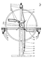
- Figs. 1 and 2 are a plan view and a side view respectively of the first embodiment of the sweeping device according to the invention.
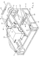
- Fig. 3 is a perspective view of a part of a second embodiment of the sweeping device according to the invention.
- the sweeping device which is shown in the drawing comprises a frame 1, which in this case consists of a horizontal cross beam 2 and a forwardly projecting longitudinal beam 3.
- a frame 1 which in this case consists of a horizontal cross beam 2 and a forwardly projecting longitudinal beam 3.
- wheels 4, 5 and 6, respectively which are rotatable about parallel horizontal axes.
- the wheels are not capable of pivoting movement about a vertical axis, but they are suspended from the associated beam 2, 3 via arms 7, 8 and 9, respectively, which are each capable of pivoting movement about an axis 10 extending parallel to the axes of wheels 4 - 6.
- Wheels 4, 5 and 6 together form the chassis of the sweeping device.
- Frame 1 supports a brush element 11 (yet to be described), which is suspended from a vertical shaft 12, which can be rotatably driven by means of a motor 13, such as a combustion engine or an electric motor. In most cases, the outgoing shaft of motor 13 will drive shaft 12 via a transmission 14. Preferably, shaft 12 can be driven at varying speeds, possibly also in opposite direction.
- An operating arm 15 comprising an operating handle 16 and being disposed in the same vertical plane as longitudinal beam 3, is provided for the purpose of driving the sweeping device. An operator can push, pull and also steer the sweeping device by means of said operating arm. Means 17 for controlling motor 13 may be present on operating arm 15, near handle 16.
- Operating arm 15 is furthermore fitted with a control lever 18, which is capable of pivoting movement about a horizontal axis and which is connected to links of a linkage system 19, which links of linkage system 19 engage arms 7 - 9 of wheels 4 - 6 in such a manner that pivoting movement of control lever 18 results in pivoting movement of arms 7 - 9 of wheels 4 - 6.
- Frame 1, and thus brush element 11, will be adjusted for height relative to the ground by the pivoting of arms 7 - 9.
- Control lever 18 is provided with a locking mechanism 20 comprising teeth 21, by means of which the control lever 18 and thus arms 7 - 9 of wheels 4 - 6 can be locked in various positions so as to make it possible to operate the brush element 11 at different heights relative to the ground.
- the brush element consists of two or four rectangular brushes 22, which are secured to a cross-like suspension 23.
- each brush 22 may be adjustably secured to suspension member 23, in such a manner that the angle in a horizontal plane between the longitudinal direction of brush 22 and the associated radial of suspension member 23 is adjustable.
- suitable adjustment of brushes 22 makes it possible to sweep the sand outwards for the final sweep-in operation, or precisely to keep the sand under the device during movement thereof for the coarser preliminary sweep-in operations. Since axis 10 extends vertically, the brush element will be in contact with the ground surface during its entire revolution, thus ensuring an efficient operation.
- the figures furthermore show that a provision 24 is present for preventing persons from coming into contact with the brushes while they are rotating.
- Said provision 24 may consist of plating or covers or the like. Also other provisions will be present so as to comply with the current standards.
- Fig. 3 shows a part of the second embodiment.
- the main difference with the first embodiment is the fact that the drive shaft 12 fitted with brush element 11, which is shown to occupy its released position, is now freely adjustable in vertical direction, so that an automatic vertical adjustment is effected. This can take place under the influence of the self-weight of the movable parts, but also under the influence of pressure means such as a (mechanical) spring member, if desired.
- brushes 22 are each capable of pivoting movement about a horizontal (radial) pivot 25. Furthermore, a rocker arm construction enables vertical movement of wheel 6, as a result of which the device can be placed in a slightly sloping position, so that the brushes 22 will only sweep flat across the ground on the side of the device remote from wheel 6. As a result of this, sand or the like will be swept to one side.
- the operating arm or pushing handle 15 is collapsible so as to make it possible to position the device with the nose wheel 5 directed upwards, for example during transport.
- the invention provides a sweeping device by means of which an operator can sweep sand into the joints of new paving or tiling without much effort.
- the device can easily be pushed ahead without reaction forces from the rotating brushes being exerted on the operator via the device.
- the working height of the brushes can be adjusted automatically or manually, by means of control lever 18 during use of the device, so as to obtain and maintain a satisfactory sweeping performance under varying sweeping conditions, also after some wear of the brushes.
- the invention is not limited to the above-described embodiment as shown in the drawing, which can be varied in several ways within the scope of the invention.
- the chassis could be fitted with a different number of, possibly pivot-mounted, wheels.
- the brush element may also consist of a large, circular brush.
- the device can also be adapted for other sweeping or polishing operations of other kinds of ground contact operations.
Landscapes
- Engineering & Computer Science (AREA)
- Architecture (AREA)
- Civil Engineering (AREA)
- Structural Engineering (AREA)
- Mining & Mineral Resources (AREA)
- Cleaning Of Streets, Tracks, Or Beaches (AREA)
- Soil Working Implements (AREA)
- Road Paving Machines (AREA)
Applications Claiming Priority (2)
| Application Number | Priority Date | Filing Date | Title |
|---|---|---|---|
| NL1008211A NL1008211C2 (nl) | 1998-02-05 | 1998-02-05 | Veeginrichting. |
| NL1008211 | 1998-02-05 |
Publications (2)
| Publication Number | Publication Date |
|---|---|
| EP0935027A2 true EP0935027A2 (de) | 1999-08-11 |
| EP0935027A3 EP0935027A3 (de) | 2000-05-24 |
Family
ID=19766473
Family Applications (1)
| Application Number | Title | Priority Date | Filing Date |
|---|---|---|---|
| EP99200330A Withdrawn EP0935027A3 (de) | 1998-02-05 | 1999-02-05 | Kehrvorrichtung |
Country Status (2)
| Country | Link |
|---|---|
| EP (1) | EP0935027A3 (de) |
| NL (1) | NL1008211C2 (de) |
Cited By (6)
| Publication number | Priority date | Publication date | Assignee | Title |
|---|---|---|---|---|
| AT407267B (de) * | 1999-03-12 | 2001-02-26 | Feurstein Guntram Ing | Vorrichtung zum einbringen von streugut in fugen eines bodenbelages |
| WO2004018775A1 (en) * | 2002-08-20 | 2004-03-04 | Zamir Manor | Apparatus and method for erasing road lane markings |
| US7003841B2 (en) | 2001-05-31 | 2006-02-28 | Johnsondiversey, Inc. | Surface treating machine |
| CN104818681A (zh) * | 2015-04-28 | 2015-08-05 | 徐趁义 | 无动力手推扫地车 |
| CN105544367A (zh) * | 2015-12-15 | 2016-05-04 | 重庆亘宇园林景观工程有限公司 | 用于道路铺砖的填缝装置 |
| CN107988973A (zh) * | 2018-01-02 | 2018-05-04 | 林继承 | 一种室外地面瓷砖缝隙自动清洁设备 |
Families Citing this family (1)
| Publication number | Priority date | Publication date | Assignee | Title |
|---|---|---|---|---|
| CN107190623B (zh) * | 2017-06-19 | 2019-05-07 | 浙江省东阳市市政环境工程有限公司 | 一种沥青路面修补车 |
Family Cites Families (6)
| Publication number | Priority date | Publication date | Assignee | Title |
|---|---|---|---|---|
| US3045267A (en) * | 1961-02-07 | 1962-07-24 | Wagner Richard Valentin | Self-adjustable rotatable surface conditioning device |
| US3115654A (en) * | 1963-02-18 | 1963-12-31 | Zimmerman Lawrence | Barn sweeper |
| CA916867A (en) * | 1970-06-03 | 1972-12-19 | Horst Elias | Sweeper |
| US3947912A (en) * | 1974-09-13 | 1976-04-06 | Abraham Michaels | Manually operated sweeper |
| DE3911291C1 (en) * | 1989-04-07 | 1990-07-26 | Sobernheimer Maschinenbau Gmbh, 6553 Sobernheim, De | Apparatus for sanding paved surfaces |
| DE4019550A1 (de) * | 1989-06-19 | 1991-01-24 | Bernhard Lamping | Kehrmaschine |
-
1998
- 1998-02-05 NL NL1008211A patent/NL1008211C2/nl not_active IP Right Cessation
-
1999
- 1999-02-05 EP EP99200330A patent/EP0935027A3/de not_active Withdrawn
Cited By (8)
| Publication number | Priority date | Publication date | Assignee | Title |
|---|---|---|---|---|
| AT407267B (de) * | 1999-03-12 | 2001-02-26 | Feurstein Guntram Ing | Vorrichtung zum einbringen von streugut in fugen eines bodenbelages |
| US7003841B2 (en) | 2001-05-31 | 2006-02-28 | Johnsondiversey, Inc. | Surface treating machine |
| WO2004018775A1 (en) * | 2002-08-20 | 2004-03-04 | Zamir Manor | Apparatus and method for erasing road lane markings |
| US7192215B2 (en) | 2002-08-20 | 2007-03-20 | Zamir Manor | Apparatus and method for erasing road lane markings |
| CN104818681A (zh) * | 2015-04-28 | 2015-08-05 | 徐趁义 | 无动力手推扫地车 |
| CN104818681B (zh) * | 2015-04-28 | 2016-06-08 | 徐趁义 | 无动力手推扫地车 |
| CN105544367A (zh) * | 2015-12-15 | 2016-05-04 | 重庆亘宇园林景观工程有限公司 | 用于道路铺砖的填缝装置 |
| CN107988973A (zh) * | 2018-01-02 | 2018-05-04 | 林继承 | 一种室外地面瓷砖缝隙自动清洁设备 |
Also Published As
| Publication number | Publication date |
|---|---|
| NL1008211C2 (nl) | 1999-08-06 |
| EP0935027A3 (de) | 2000-05-24 |
Similar Documents
| Publication | Publication Date | Title |
|---|---|---|
| US5238323A (en) | Riding trowel for concrete finishing | |
| US4602400A (en) | Sweeping apparatus | |
| US5284218A (en) | Motorized cart with front wheel drive | |
| EP0800809B1 (de) | Rollstuhlrahmen | |
| US5039123A (en) | Wheel trolley | |
| US4483041A (en) | Support for a squeegee assembly | |
| JPH0351362B2 (de) | ||
| AU7884898A (en) | Invalid hoists | |
| US2709269A (en) | Floor sweeper | |
| CA2389442A1 (en) | An articulated rotary mower | |
| EP0965259B1 (de) | Verbindungsmechanismus | |
| EP0120931A1 (de) | Schmutzaufnahmesystem für strassenkehrmaschinen | |
| US4836320A (en) | Turning apparatus for handle-operated equipment | |
| US5181294A (en) | Support and manipulation mechanism for leaf and debris collector | |
| CA2207767A1 (en) | Lost motion lift control for a mower deck | |
| EP0866172A2 (de) | Saug- und Kehrvorrichtung | |
| US6299257B1 (en) | Machine for removing tile with articulated frame | |
| US2263722A (en) | Power sweeper | |
| US3087180A (en) | Power sweeper | |
| JPH1129914A (ja) | 除雪機の除雪高さ調節機構 | |
| NL1008211C2 (nl) | Veeginrichting. | |
| EP0199370B1 (de) | Kehrmaschine | |
| EP0843046A1 (de) | Vorrichtung zum Kehren und Aufnehmen von Material | |
| JPH0124180Y2 (de) | ||
| FR2943211A1 (fr) | Faneuse equipee d'une roue palpeuse a adaptabilite amelioree |
Legal Events
| Date | Code | Title | Description |
|---|---|---|---|
| PUAI | Public reference made under article 153(3) epc to a published international application that has entered the european phase |
Free format text: ORIGINAL CODE: 0009012 |
|
| AK | Designated contracting states |
Kind code of ref document: A2 Designated state(s): AT BE CH CY DE DK ES FI FR GB GR IE IT LI LU MC NL PT SE |
|
| AX | Request for extension of the european patent |
Free format text: AL;LT;LV;MK;RO;SI |
|
| PUAL | Search report despatched |
Free format text: ORIGINAL CODE: 0009013 |
|
| AK | Designated contracting states |
Kind code of ref document: A3 Designated state(s): AT BE CH CY DE DK ES FI FR GB GR IE IT LI LU MC NL PT SE |
|
| AX | Request for extension of the european patent |
Free format text: AL;LT;LV;MK;RO;SI |
|
| AKX | Designation fees paid | ||
| REG | Reference to a national code |
Ref country code: DE Ref legal event code: 8566 |
|
| STAA | Information on the status of an ep patent application or granted ep patent |
Free format text: STATUS: THE APPLICATION IS DEEMED TO BE WITHDRAWN |
|
| 18D | Application deemed to be withdrawn |
Effective date: 20001127 |