EP0935062A2 - Dieselmotorzylinderkopf mit obenliegenden Ventilen - Google Patents
Dieselmotorzylinderkopf mit obenliegenden Ventilen Download PDFInfo
- Publication number
- EP0935062A2 EP0935062A2 EP99101501A EP99101501A EP0935062A2 EP 0935062 A2 EP0935062 A2 EP 0935062A2 EP 99101501 A EP99101501 A EP 99101501A EP 99101501 A EP99101501 A EP 99101501A EP 0935062 A2 EP0935062 A2 EP 0935062A2
- Authority
- EP
- European Patent Office
- Prior art keywords
- inlet
- head
- exhaust
- head according
- valve
- Prior art date
- Legal status (The legal status is an assumption and is not a legal conclusion. Google has not performed a legal analysis and makes no representation as to the accuracy of the status listed.)
- Withdrawn
Links
- 238000002485 combustion reaction Methods 0.000 claims description 7
- 239000000446 fuel Substances 0.000 claims description 4
- 230000000295 complement effect Effects 0.000 claims description 2
- 230000006835 compression Effects 0.000 description 6
- 238000007906 compression Methods 0.000 description 6
- 230000002000 scavenging effect Effects 0.000 description 6
- 239000007789 gas Substances 0.000 description 4
- 238000002347 injection Methods 0.000 description 4
- 239000007924 injection Substances 0.000 description 4
- 238000001816 cooling Methods 0.000 description 3
- 238000004880 explosion Methods 0.000 description 2
- 239000007788 liquid Substances 0.000 description 2
- 238000012986 modification Methods 0.000 description 2
- 230000004048 modification Effects 0.000 description 2
- 238000005266 casting Methods 0.000 description 1
- 238000010276 construction Methods 0.000 description 1
- 239000000110 cooling liquid Substances 0.000 description 1
- 238000006073 displacement reaction Methods 0.000 description 1
- 230000000694 effects Effects 0.000 description 1
- 230000000670 limiting effect Effects 0.000 description 1
- 239000000463 material Substances 0.000 description 1
- 229910001092 metal group alloy Inorganic materials 0.000 description 1
- 230000001681 protective effect Effects 0.000 description 1
- 238000005096 rolling process Methods 0.000 description 1
- 238000007789 sealing Methods 0.000 description 1
Images


Classifications
-
- F—MECHANICAL ENGINEERING; LIGHTING; HEATING; WEAPONS; BLASTING
- F02—COMBUSTION ENGINES; HOT-GAS OR COMBUSTION-PRODUCT ENGINE PLANTS
- F02F—CYLINDERS, PISTONS OR CASINGS, FOR COMBUSTION ENGINES; ARRANGEMENTS OF SEALINGS IN COMBUSTION ENGINES
- F02F1/00—Cylinders; Cylinder heads
- F02F1/24—Cylinder heads
- F02F1/26—Cylinder heads having cooling means
- F02F1/36—Cylinder heads having cooling means for liquid cooling
- F02F1/38—Cylinder heads having cooling means for liquid cooling the cylinder heads being of overhead valve type
-
- F—MECHANICAL ENGINEERING; LIGHTING; HEATING; WEAPONS; BLASTING
- F02—COMBUSTION ENGINES; HOT-GAS OR COMBUSTION-PRODUCT ENGINE PLANTS
- F02B—INTERNAL-COMBUSTION PISTON ENGINES; COMBUSTION ENGINES IN GENERAL
- F02B2275/00—Other engines, components or details, not provided for in other groups of this subclass
- F02B2275/16—Indirect injection
-
- F—MECHANICAL ENGINEERING; LIGHTING; HEATING; WEAPONS; BLASTING
- F02—COMBUSTION ENGINES; HOT-GAS OR COMBUSTION-PRODUCT ENGINE PLANTS
- F02B—INTERNAL-COMBUSTION PISTON ENGINES; COMBUSTION ENGINES IN GENERAL
- F02B2275/00—Other engines, components or details, not provided for in other groups of this subclass
- F02B2275/18—DOHC [Double overhead camshaft]
-
- F—MECHANICAL ENGINEERING; LIGHTING; HEATING; WEAPONS; BLASTING
- F02—COMBUSTION ENGINES; HOT-GAS OR COMBUSTION-PRODUCT ENGINE PLANTS
- F02B—INTERNAL-COMBUSTION PISTON ENGINES; COMBUSTION ENGINES IN GENERAL
- F02B3/00—Engines characterised by air compression and subsequent fuel addition
- F02B3/06—Engines characterised by air compression and subsequent fuel addition with compression ignition
-
- F—MECHANICAL ENGINEERING; LIGHTING; HEATING; WEAPONS; BLASTING
- F02—COMBUSTION ENGINES; HOT-GAS OR COMBUSTION-PRODUCT ENGINE PLANTS
- F02F—CYLINDERS, PISTONS OR CASINGS, FOR COMBUSTION ENGINES; ARRANGEMENTS OF SEALINGS IN COMBUSTION ENGINES
- F02F1/00—Cylinders; Cylinder heads
- F02F1/24—Cylinder heads
- F02F2001/244—Arrangement of valve stems in cylinder heads
- F02F2001/247—Arrangement of valve stems in cylinder heads the valve stems being orientated in parallel with the cylinder axis
-
- Y—GENERAL TAGGING OF NEW TECHNOLOGICAL DEVELOPMENTS; GENERAL TAGGING OF CROSS-SECTIONAL TECHNOLOGIES SPANNING OVER SEVERAL SECTIONS OF THE IPC; TECHNICAL SUBJECTS COVERED BY FORMER USPC CROSS-REFERENCE ART COLLECTIONS [XRACs] AND DIGESTS
- Y02—TECHNOLOGIES OR APPLICATIONS FOR MITIGATION OR ADAPTATION AGAINST CLIMATE CHANGE
- Y02T—CLIMATE CHANGE MITIGATION TECHNOLOGIES RELATED TO TRANSPORTATION
- Y02T10/00—Road transport of goods or passengers
- Y02T10/10—Internal combustion engine [ICE] based vehicles
- Y02T10/12—Improving ICE efficiencies
Definitions
- the present invention relates to a Diesel engine head with overhead inlet and exhaust valves, particularly for two-stroke engines.
- Two-stroke Diesel engines are known, although their use is limited; their operating cycle is composed of a compression and explosion stroke followed by an expansion and burnt-gas exhaust stroke.
- An adapted injector operated by a pump, is used to inject the atomized fuel in the combustion chamber, while the stroke for expelling the combustion products and introducing air, called scavenging, is managed by means of the stroke of the piston, which opens and closes the inlet and exhaust ports for the gases.
- Such ports are normally formed in the rim of the cylinder and have a rather small surface
- valves As regards four-stroke engines, an overhead arrangement of the valves is very common; such valves usually have a rather small circular cross-section, and the impulses for opening the valves are transmitted by means of one or more camshafts which can be installed in the head or externally thereto.
- the aim of the present invention is to obviate the drawbacks of conventional devices by providing a Diesel engine head which is provided with overhead inlet and exhaust valves having a large cross-section, adapted to be fitted to a cylinder having walls with no openings, and adapted to let a large inflow of air into the cylinder during scavenging.
- an object of the present invention is to provide an engine head which is capable of adapting, with a small number of simple modifications, even to four-stroke or gasoline-fueled engines, and capable of working with a sufficiently low compression ratio and of being particularly quiet.
- Another object of the present invention is to achieve the above aim with a structure which is simple, relatively easy to provide in practice, safe in use, effective in operation and having a relatively low cost.
- a head for a Diesel engine with overhead inlet and exhaust valves comprising a base which is meant to close the cylinder and is crossed by an inlet port and by an exhaust port, characterized in that said inlet and exhaust ports have an annular shape and are substantially coaxial to a vertical axis of the head.
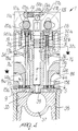
- the reference numeral 1 generally designates a head for a two-stroke Diesel engine with overhead inlet and exhaust valves according to the invention.
- the head comprises a block 2 which is substantially shaped like a parallelepiped and is advantageously obtained by casting metal alloys.
- a frustum-shaped protrusion 3 protrudes downwards from the base of the block 2, is axially aligned with the cylinder and is internally provided with a seat for an injector 4.
- the smaller inner one, 5, is meant to act as exhaust, while the larger outer one, 6, is meant to act as inlet.
- the ports 5 and 6 are connected to respective bell-shaped cavities 5a, 6a which are coaxial to the protrusion 3 and are formed in the block 2.
- the bell-shaped cavities 5a and 6a in turn open onto each one of two parallel sides of the block 1 with two respective mutually opposite exhaust and inlet openings 7a, 7b and 8a, 8b.
- the ports 5 and 6 can be closed by two annular valves, an exhaust valve 9 and an inlet valve 10. Both the exhaust valve 9 and the inlet valve 10 have frustum-shaped inner and outer edges which are shaped complementarily to the ports that they close and respectively form inner and outer double seats, both of which are advantageously inclined at 45°.
- Two front shoulders 11a and 11b are fixed in the upper part of the head, as a continuation of the faces of the block 2 that are not affected by the exhaust and inlet ports 7 and 8.
- Two camshafts 12a and 12b are rotatably mounted in the shoulders and are thus arranged on axes which are parallel to the sides of the block 2 onto which the openings 7 and 8 open.
- gears 13a and 13b which are keyed symmetrically and mesh together so as to make the two shafts rotate in mutually opposite directions.
- the valve 9 is rigidly coupled to two stems 14a and 14b which are perpendicular to the plane of the valve, are arranged at 180° with respect to each other and are fixed to the valve by screwing their threaded ends in respective threaded holes 15a and 15b.
- stems 16a, 16b, 16c, 16d are fixed above the inlet valve 10 and are distributed symmetrically at 90° with respect to each other.
- stem 14a is described in detail as regards the parts that are similar in all the stems.
- the stem 14a passes vertically through the block 2 inside a respective guiding seat 18a until it reaches a cavity 17a which has a wider diameter and is located in the upper part of the block 2.
- the upper end of the stem 14a has a sort of mushroom-shaped part 141 which is rigidly coupled thereto and forms, in a downward region, an annular seat which accommodates one end of a helical compression spring 19.
- Spring 19 is mounted coaxially on the stem 14a and presses, with its other end, against the base of the respective cavity 17a.
- the mushroom-shaped part 141 has, on its outer lateral surface, two mutually opposite upper flat regions which, during assembly, facilitate engagement with an adapted wrench for screwing in a threaded hole 15a formed in the exhaust valve 9; with its upper face, the mushroom-shaped part 141 is in contact with a cap-shaped tappet 20a which closes the upper opening of the cavity 17a.
- tappets 20a, 20b and 21a, 21b, 21c, 21d are provided and specifically tappets 20a, 20b and 21a, 21b, 21c, 21d, arranged in sets of three along the two axes of the shafts 12a and 12b, and a respective actuation cam is mounted on each shaft above each tappet.
- the cams 22a, 22b, 22c, 22d act on the tappets 21a, 21b, 21c, 21d which actuate the opening of the inlet valve 10, while the cams 23a and 23b, which are respectively interposed on the two shafts between the cams 22a, 22b and 22c, 22d, actuate the tappets 20a, 20b which actuate the exhaust valve 9; the closure of the exhaust and inlet valves 9 and 10 is actuated by the helical compression springs 19.
- a rocker 24 is pivoted between the shoulders 11a and 11b to a shaft 24a which is parallel to, and arranged above, the axes of the shafts 12.
- the rocker is meant to actuate a pump in axial alignment with the injector 4, and has a substantially T-like shape in plan view.
- the rocker forms, in a rear part of the shaft 24a, two forks 24c, 24d which lie above the shaft 12a and in which two rolling rollers 25a and 25c are pivoted so as to rotate with axes which are parallel to said shaft.
- the rollers rest rotatably on the respective cams 22a and 22c.
- the other front part 24e of the rocker 24 of the pump rests on a roller 26 which is mounted so that it can rotate by means of a pivot 26a at the upper fork-like end 27a of a tappet 27b which actuates an injection pump 28 in axial alignment with the injector 4.
- the pump 28 is inserted in a respective vertical cylindrical cavity 29 formed at the center of the block 2 and has, according to the prior art, two rings 30 and 31 (which are coaxial to the pump 28 and are formed between three sealing rings which are known by the trade-name O-Ring and are designated by the reference numerals 32a, 32b and 32c) which are connected respectively to the exhaust duct 33 and inlet duct 34 through a series of radial perforations formed in their surface.
- a nozzle 35 is fixed to the lower end of the pump, passes through the frustum-shaped protrusion 3 and ends with the injector 4.
- the combustion chamber 37 is preferably spherical and is formed inside the piston top 38: a frustum-shaped opening of appropriate diameter is formed on the upper face of the piston and its oblique lateral wall 39 is parallel to the lateral surface of the protrusion, so that when the piston is in the top dead center the inlet of the combustion chamber 37 is closed almost hermetically by the protrusion 3, forming a choke for the forced passage of the gases.
- the operation of the head according to the invention is as follows. During the descent of the piston, the inlet and exhaust valves 10, 9 are open, allowing to expel the burnt gases and to draw air (cylinder scavenging). When the piston begins its upward movement, approximately 20° after the lower dead center, the exhaust valve 9 closes, while the inlet valve 10 remains open to approximately 30° or more, when it too closes.
- the upward movement of the piston compresses the air inside the cylinder and consequently increases the temperature.
- the frustum-shaped protrusion 3 enters the upper opening of the combustion chamber 37 and the particular complementary configuration of the contour 39 of the opening and of the protrusion 3 determines, due to the known Venturi effect, a further increase in the temperature inside the combustion chamber.
- This further temperature increase allows to ignite the fuel with a rather low compression ratio of approximately 16:1.
- valves 9 and 10 The opening of the valves 9 and 10 is actuated by the two contrarotating overhead distribution camshafts 12a, 12b: the cams 22 act simultaneously on the four tappets 21 for actuating the stems connected to the inlet valve 10, provided with a larger diameter, while the cams 23 act simultaneously on the two tappets 20 related to the stems that are fixed to the exhaust valve 9, having a smaller diameter, so as to move the valves parallel to themselves.
- the cams 22a and 22c also synchronously actuate the injection pump by acting on the rollers 25a and 25c of the rocker 24 of the pump.
- connection of the exhaust and inlet ports to two openings 7 and to two openings 8 on the two mutually opposite sides of the block 2 allows to add a series of devices meant to improve the overall performance of the engine.
- the cylinders are mutually aligned so that the two distribution camshafts 12a and 12b lie above all of the head, so that the pairs of lateral openings 7 and 8 of the various cylinders are aligned and arranged side by side to be connected to two inlet ducts and to two exhaust ducts which are arranged laterally and longitudinally and so that the various cylinders affect a lower longitudinal crankshaft which is parallel to the distribution shafts 12.
- Any cavities 36 for circulating the liquid for cooling the various cylinders are also mutually aligned and connected.
Landscapes
- Engineering & Computer Science (AREA)
- Chemical & Material Sciences (AREA)
- Combustion & Propulsion (AREA)
- Mechanical Engineering (AREA)
- General Engineering & Computer Science (AREA)
- Valve-Gear Or Valve Arrangements (AREA)
- Cylinder Crankcases Of Internal Combustion Engines (AREA)
Applications Claiming Priority (2)
| Application Number | Priority Date | Filing Date | Title |
|---|---|---|---|
| ITBO980055 | 1998-02-04 | ||
| IT98BO000055A IT1299831B1 (it) | 1998-02-04 | 1998-02-04 | Testata per motore diesel con valvole di aspirazione e scarico in testa. |
Publications (2)
| Publication Number | Publication Date |
|---|---|
| EP0935062A2 true EP0935062A2 (de) | 1999-08-11 |
| EP0935062A3 EP0935062A3 (de) | 2000-04-26 |
Family
ID=11342832
Family Applications (1)
| Application Number | Title | Priority Date | Filing Date |
|---|---|---|---|
| EP99101501A Withdrawn EP0935062A3 (de) | 1998-02-04 | 1999-01-27 | Dieselmotorzylinderkopf mit obenliegenden Ventilen |
Country Status (2)
| Country | Link |
|---|---|
| EP (1) | EP0935062A3 (de) |
| IT (1) | IT1299831B1 (de) |
Cited By (1)
| Publication number | Priority date | Publication date | Assignee | Title |
|---|---|---|---|---|
| DE102014009349A1 (de) * | 2014-06-29 | 2015-12-31 | Dirk Ohlmann | Verbrennungsmotor |
Family Cites Families (3)
| Publication number | Priority date | Publication date | Assignee | Title |
|---|---|---|---|---|
| AU4838990A (en) * | 1989-02-02 | 1990-08-24 | Helmut Konig | Internal combustion engine |
| DE4003498A1 (de) * | 1990-02-06 | 1990-07-05 | Schwartz Helma | Zylinderkopf fuer hochleistungs-brennkraftmaschinen, insbesondere ottomotoren, mit neuartigen doppelsitz-ringventilen, dual-beatmungssystem und drial-zuendanlage |
| DE19705659A1 (de) * | 1997-02-14 | 1998-08-20 | Guenter Dr Ing Slowik | Verfahren zum Betreiben einer Brennkraftmaschine |
-
1998
- 1998-02-04 IT IT98BO000055A patent/IT1299831B1/it active IP Right Grant
-
1999
- 1999-01-27 EP EP99101501A patent/EP0935062A3/de not_active Withdrawn
Cited By (3)
| Publication number | Priority date | Publication date | Assignee | Title |
|---|---|---|---|---|
| DE102014009349A1 (de) * | 2014-06-29 | 2015-12-31 | Dirk Ohlmann | Verbrennungsmotor |
| WO2016000672A1 (de) | 2014-06-29 | 2016-01-07 | Dirk Ohlmann | Zvlinderkopf und verbrennungsmotor |
| DE102014009349B4 (de) * | 2014-06-29 | 2016-01-28 | Dirk Ohlmann | Verbrennungsmotor |
Also Published As
| Publication number | Publication date |
|---|---|
| EP0935062A3 (de) | 2000-04-26 |
| IT1299831B1 (it) | 2000-04-04 |
| ITBO980055A1 (it) | 1999-08-04 |
| ITBO980055A0 (it) | 1998-02-04 |
Similar Documents
| Publication | Publication Date | Title |
|---|---|---|
| US3774581A (en) | Combination poppet and reed valve | |
| US4067302A (en) | Two-stroke internal combustion engine and method of operation thereof | |
| US6443110B2 (en) | Rotary valve head system for multi-cylinder internal combustion engines | |
| JPH10184323A (ja) | 4サイクルエンジン | |
| KR940009517A (ko) | 스파크 점화되는 내연 기관 | |
| JP2001050102A (ja) | 4サイクルエンジン | |
| US3987769A (en) | Jet ignition engine with valve-carried ignition chamber | |
| US3182645A (en) | Internal combustion engine | |
| US4307687A (en) | Internal combustion engines | |
| JP3333298B2 (ja) | 筒内燃料噴射式の多気筒エンジン | |
| AU669404B2 (en) | Exhaust control device for a two-cycle engine | |
| US4458635A (en) | Two-cycle internal combustion engine | |
| US5908012A (en) | Combustion control device for an engine | |
| US5816202A (en) | High efficiency explosion engine with a double acting piston | |
| JPH07102915A (ja) | 4サイクルエンジン | |
| EP0935062A2 (de) | Dieselmotorzylinderkopf mit obenliegenden Ventilen | |
| WO2006024082A3 (en) | Internal combustion engine with rotary valve | |
| IT9019920A1 (it) | Motore a combustione interna con luce di scarico sul cilindro | |
| US5603291A (en) | Internal combustion engine with valve built into piston head | |
| EP0342893A1 (de) | Brennkraftmaschine | |
| US3905344A (en) | Internal combustion engine | |
| CN100416060C (zh) | 双冲程发动机 | |
| US6209512B1 (en) | Small-dimension two or four stroke vehicle engine with stratified feed | |
| CN107110042A (zh) | 柴油发动机以及用于起动柴油发动机的方法 | |
| GB2272941A (en) | Two-stroke engine. |
Legal Events
| Date | Code | Title | Description |
|---|---|---|---|
| PUAI | Public reference made under article 153(3) epc to a published international application that has entered the european phase |
Free format text: ORIGINAL CODE: 0009012 |
|
| AK | Designated contracting states |
Kind code of ref document: A2 Designated state(s): AT BE CH CY DE DK ES FI FR GB GR IE IT LI LU MC NL PT SE |
|
| AX | Request for extension of the european patent |
Free format text: AL;LT;LV;MK;RO;SI |
|
| PUAL | Search report despatched |
Free format text: ORIGINAL CODE: 0009013 |
|
| AK | Designated contracting states |
Kind code of ref document: A3 Designated state(s): AT BE CH CY DE DK ES FI FR GB GR IE IT LI LU MC NL PT SE |
|
| AX | Request for extension of the european patent |
Free format text: AL;LT;LV;MK;RO;SI |
|
| RIC1 | Information provided on ipc code assigned before grant |
Free format text: 7F 02F 1/38 A, 7F 01L 1/28 B |
|
| AKX | Designation fees paid | ||
| STAA | Information on the status of an ep patent application or granted ep patent |
Free format text: STATUS: THE APPLICATION IS DEEMED TO BE WITHDRAWN |
|
| 18D | Application deemed to be withdrawn |
Effective date: 20001027 |
|
| REG | Reference to a national code |
Ref country code: DE Ref legal event code: 8566 |