EP0935121B1 - Verfahren zur Verbesserung der Leistung eines optischen Faserkreisels - Google Patents
Verfahren zur Verbesserung der Leistung eines optischen Faserkreisels Download PDFInfo
- Publication number
- EP0935121B1 EP0935121B1 EP99102242A EP99102242A EP0935121B1 EP 0935121 B1 EP0935121 B1 EP 0935121B1 EP 99102242 A EP99102242 A EP 99102242A EP 99102242 A EP99102242 A EP 99102242A EP 0935121 B1 EP0935121 B1 EP 0935121B1
- Authority
- EP
- European Patent Office
- Prior art keywords
- fiber
- bias
- light
- determining
- phase
- Prior art date
- Legal status (The legal status is an assumption and is not a legal conclusion. Google has not performed a legal analysis and makes no representation as to the accuracy of the status listed.)
- Expired - Lifetime
Links
- 238000000034 method Methods 0.000 title claims description 18
- 239000013307 optical fiber Substances 0.000 claims description 16
- 230000000694 effects Effects 0.000 description 5
- 239000000835 fiber Substances 0.000 description 5
- 230000010363 phase shift Effects 0.000 description 5
- 230000001419 dependent effect Effects 0.000 description 2
- 238000010586 diagram Methods 0.000 description 2
- 230000014509 gene expression Effects 0.000 description 2
- 238000005259 measurement Methods 0.000 description 2
- 230000001427 coherent effect Effects 0.000 description 1
- 238000006880 cross-coupling reaction Methods 0.000 description 1
- 230000007423 decrease Effects 0.000 description 1
- 230000003247 decreasing effect Effects 0.000 description 1
- 239000000284 extract Substances 0.000 description 1
- 230000003287 optical effect Effects 0.000 description 1
- 230000010287 polarization Effects 0.000 description 1
- 230000001902 propagating effect Effects 0.000 description 1
- 238000005295 random walk Methods 0.000 description 1
- 238000007670 refining Methods 0.000 description 1
Images

Classifications
-
- G—PHYSICS
- G01—MEASURING; TESTING
- G01C—MEASURING DISTANCES, LEVELS OR BEARINGS; SURVEYING; NAVIGATION; GYROSCOPIC INSTRUMENTS; PHOTOGRAMMETRY OR VIDEOGRAMMETRY
- G01C19/00—Gyroscopes; Turn-sensitive devices using vibrating masses; Turn-sensitive devices without moving masses; Measuring angular rate using gyroscopic effects
- G01C19/58—Turn-sensitive devices without moving masses
- G01C19/64—Gyrometers using the Sagnac effect, i.e. rotation-induced shifts between counter-rotating electromagnetic beams
- G01C19/72—Gyrometers using the Sagnac effect, i.e. rotation-induced shifts between counter-rotating electromagnetic beams with counter-rotating light beams in a passive ring, e.g. fibre laser gyrometers
- G01C19/721—Details, e.g. optical or electronical details
Definitions
- This invention relates generally to fiber-optic gyros and more specifically to the signal processing associated with fiber-optic gyros.
- Fiber-optic gyros measure rate of rotation by determining the phase difference in light waves that propagate in opposite directions through a coil wound with optical fiber.
- Light waves that propagate through the coil in the direction of rotation take a longer time than light waves that propagate through the coil in the direction opposite to the direction of rotation. This difference in time, measured as the phase difference between counter-propagating light waves, is proportional to the angular velocity of the coil.
- FIG. 1 A typical block diagram for a fiber-optic gyro is shown in Fig. 1.
- a light source 2 supplies a reasonably coherent light beam to the optical-fiber interferometer 4 which causes the input light beam to be split into two light beams that are fed into opposite ends of an optical fiber configured as a coil.
- the light beams emerging from opposite ends of the optical fiber are recombined into a single output light beam which feeds into the detector 6.
- ⁇ ( t ) is the phase-modulation generating function
- ⁇ ( t ) mod 2 ⁇ is the phase modulation introduced by a phase modulator at one end of the fiber-optic coil in the interferometer 4
- ⁇ is the propagation time through the fiber optic coil
- ( ⁇ s + 2 ⁇ n ) is the so-called Sagnac phase resulting from the rotation of the fiber-optic coil about its axis.
- the integer n (called the Sagnac fringe number) is either positive or negative and the Sagnac residual phase ⁇ s is constrained to the range - ⁇ ⁇ ⁇ s ⁇ ⁇ .
- the output of the detector 6 is converted to digital form by the analog-to-digital converter 8 and then processed in the digital processor 10 to yield at the output a measure of the rate and angle of rotation of the interferometer 4.
- the digital processor 10 generates a phase-modulation generating function ⁇ ( t ), the modulo-2 ⁇ portion of which is converted to analog form by the digital-to-analog converter 12 and supplied to the phase modulator in the interferometer 4.
- the phase-modulation generating function ⁇ ( t ) typically consists of a number of phase-modulation components among which are ⁇ SE ( t ) and ⁇ M ( t ).
- the phase- modulation component ⁇ SE ( t ) is typically a stepped waveform with steps that change in height by - ⁇ SE at ⁇ intervals where ⁇ SE is an estimate of ⁇ s .
- the ⁇ SE ( t ) modulation cancels in large part ⁇ s .
- the accurate measurement of the uncancelled portion of the Sagnac residual phase ⁇ s is of great importance in that it is the quantity that is used in refining the estimate of the Sagnac phase and generating the ⁇ SE ( t ) phase-modulation component.
- ⁇ M ( t ) phase-modulation component such that [ ⁇ M ( t )- ⁇ M ( t - ⁇ )] is equal to j ⁇ M where the permitted values of j are the values -1 and 1 and ⁇ M is a predetermined positive phase angle somewhere in the vicinity ⁇ /2 radians where the slope of the cosine function is greatest.
- ⁇ M ( t ) be a square wave with amplitude ⁇ /2 and period 2 ⁇ .
- the ⁇ M ( t ) modulation can also be a stepped function wherein the phase increases or decreases at ⁇ intervals by ⁇ M .
- [ ⁇ ( t )] mod 2 ⁇ - [ ⁇ ( t - ⁇ )] mod 2 ⁇ 2 ⁇ k - ⁇ SE + j ⁇ M
- Fiber optic gyros generally employ broadband light sources in order to avoid polarization cross-coupling effects as the light propagates through the fiber.
- coherence is lost as non-reciprocal phase shifts between the clockwise and counter-clockwise beams are introduced. This leads to the "fringe visibility effect" whereby the interference pattern between the two beams loses contrast as the difference in optical paths increases.
- a method for determining a bias in a fiber-optic gyro comprising counter-propagating light beams from a broadband source as set forth in claim 1, is provided.
- Preferred embodiments of the present invention are disclosed in the dependent claims.
- the invention is a method for improving the performance of a fiber-optic gyro comprising counter-propagating light beams from a broadband source in an optical fiber configured as a coil.
- the fiber-optic gyro is of the type where the phases of the light beams are step-modulated at one or both ends of the optical fiber at time intervals equal to the light propagation time ⁇ through the optical fiber, the step being in the range from 0 to 2 ⁇ - ⁇ radians where ⁇ is an infinitesimal.
- the step is the sum of an estimate of the Sagnac phase residual ⁇ SE with reversed sign and the quantity (2 ⁇ k + j ⁇ M ) where the index k can take on the values -1, 0, and 1, and the index j can take on the values -1 and 1.
- the phase angle ⁇ M is a positive constant less than ⁇ radians.
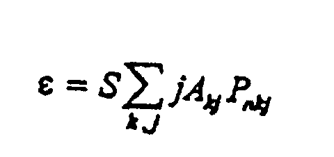
- the method comprises the steps of determining the interferometer output light intensity, determining the Sagnac fringe number n , calculating the error P nkj in the interferometer output light intensity attributable to the use of a broadband light-beam source for particular values of an index pair ( k,j ), determining estimates A kj of the probabilities of the index pairs ( k,j ) by counting the occurrences of each index pair ( k,j ) over a period of time, and determining the bias ⁇ in the output of a fiber-optic gyro using the equation where S is the scale factor that translates interferometer output light intensity error into rotation rate of the fiber-optic gyro.
- the presence of the j within the summation represents the demodulation of the interferometer output which extracts the rate information.
- FIG. 1 is a block diagram of a fiber-optic gyro and associated control loop.
- the quantity P nkj is the error in the measured intensity I from the interferometer.
- the resulting bias ⁇ in the output from the fiber-optic gyro is then given by where S is the scale factor that translates interferometer intensity variations into rotation rate of the fiber-optic coil and A kj is an estimate of the probability of the index pair ( k,j) .
- S is inversely proportional to the Sagnac scale factor of the gyro.
- phase-modulating function having the prescribed statistical properties results in a bias ⁇ in the output from the fiber-optic gyro that is independent of the Sagnac fringe number n .
- Estimates of the A's can be obtained by counting the occurrences of the index pairs ( k,j ) during operation.
- the invention relates to a method for determining bias in a fiber-optic gyro comprising counter-propagating light beams from a broadband source in an optical fiber, the phases of the light beams being step-modulated at one or both ends of the optical fiber at time intervals approximately equal to the light propagation time ⁇ through the optical fiber, the step being in the range from 0 to 2 ⁇ - ⁇ radians, ⁇ being an infinitesimal, the step being the sum of an estimate of the Sagnac phase residual ⁇ SE with reversed sign and the quantity (2 ⁇ k + j ⁇ M ), the permitted values of the index k being the values -1, 0, and 1, the permitted values of the index j being the values -1 and 1, the phase angle ⁇ M being a positive constant less than ⁇ radians, the method comprising the step: determining the interferometer output light intensity.
Landscapes
- Physics & Mathematics (AREA)
- Engineering & Computer Science (AREA)
- Optics & Photonics (AREA)
- Electromagnetism (AREA)
- Power Engineering (AREA)
- General Physics & Mathematics (AREA)
- Radar, Positioning & Navigation (AREA)
- Remote Sensing (AREA)
- Gyroscopes (AREA)
Claims (10)
- Ein Verfahren zur Bestimmung der Vorspannung in einem faseroptischen Kreisel, der sich entgegengesetzt fortpflanzende Lichtstrahlen von einer Breitbandquelle (2) in einer optische Faser aufweist, wobei die Phasen der Lichtstrahlen schrittmoduliert sind, an einem oder beiden Enden der optischen Faser, und zwar zu Zeitintervallen annähernd gleich der Lichtfortpflanzungszeit τ durch die optische Faser, wobei der Schritt im Bereich von 0 bis 2 π - δ Radian liegt, wobei δ ein infinitesimaler Wert ist, wobei der Schritt die Summe einer Schätzung des Sagnac Phasenrests ϕSE ist mit umgekehrten Vorzeichen und der Größe (2πk + jM), die gestatteten Werte des Index k die Werte -1, 0 und 1 sind, die gestatteten Werte des Index j die Werte -1 und 1 sind, der Phasenwinkel M eine positive Konstante kleiner als π Radian ist und das Verfahren die folgenden Schritte aufweist:Bestimmen einer Interferometer (4) Ausgangslichtintensität;Berechnen der Vorspannung ε in der Interferometer (4) Ausgangslichtintensität die zurückzuführen ist auf die Verwendung der Breitbandlichtstrahlquelle (2).
- Verfahren nach Anspruch 1, wobei eine Phasenmodulations-Erzeugungsfunktion { (t)} mod2π definiert wird durch die GleichungBestimmen des Wertes des Index k aus den Werten von h und c, wobei h gleich Null ist, wenn das Zeichen von {-SE + jM) positiv ist, wobei h ansonsten gleich Eins ist, wobei c gleich Null ist, wenn {(t-τ)}mod2π + 2πh - SE + jM kleiner als 2π ist, wobei c ansonsten gleich 1 ist.
- Verfahren gemäß Anspruch 1, wobei ferner der folgende Schritt vorgesehen ist:Bestimmung der Vorspannung ε in der Ausgangsgröße des faseroptischen Kreisels, zurückzuführen auf die Verwendung der Breitbandlichtstrahlenquelle (2) unter Verwendung von Lichtintensitätsfehlern Pakj, wobei n die Sagnac Rand- oder Fringezahl ist.
- Verfahren nach Anspruch 3, wobei die Vorspannung ε unabhängig von der Sagnac Fringe- oder Randzahl ist.
- Verfahren nach Anspruch 1, wobei ferner der folgende Schritt vorgesehen ist:Bestimmung von Schätzungen Akj der Wahrscheinlichkeiten von Indexpaaren (kj) durch Zählen der Auftritte jedes Indexpaars (kj) über eine Zeitperiode hinweg.
- Verfahren nach Anspruch 5, wobei ferner der folgende Schritt vorgesehen ist:Bestimmung der Vorspannung ε in der Ausgangsgröße des faseroptischen Kreisels, zurückzuführen auf die Verwendung einer Breitband-Lichtstrahlquelle (2) unter Verwendung der Gleichung:oder einem Äquivalent davon, wobei Pakj die Lichtintensitätsfehler sind, n die Sagnac Randzahl ist, S der Maßstabs- oder Scale-Faktor ist, der die Interferometerintensitätsvariation in die Rotationsrate oder Rotationsgeschwindigkeit des faseroptischen Kreisels überträgt.
- Verfahren nach Anspruch 6, wobei die Vorspannung unabhängig von der Sagnac Randzahl ist.
- Verfahren nach Anspruch 5, wobei der folgende Schritt vorgesehen ist:Bestimmung der Vorspannung ε in der Ausgangsgröße des faseroptischen Kreisels zurückzuführen auf die Verwendung einer Breitbandlichtstrahlquelle (2) unter Verwendung der Gleichungoder einem Äquivalent davon, wobei S der Skalen- oder Maßstabsfaktor ist, der die Interferometerintensitätsvariationen in die Drehrate bzw. Drehgeschwindigkeit des faseroptischen Kreisels überträgt, und wobei β eine Konstante ist für eine spezielle faseroptische Kreiselkonfiguration.

- Verfahren nach Anspruch 1, wobei der Lichtintensitätsfehler Pakj annähernd proportional zu 2cos ist, wobei die Differenz in der Phase der Lichtstrahlen ist, die aus jedem Ende der optischen Faser austreten, wobei n die Sagnac Randzahl ist.
- Verfahren nach Anspruch 1, wobei der Lichtintensitätsfehler Pakj annähernd proportional zu (n+k)(n+k+j M / π) ist.
Applications Claiming Priority (2)
| Application Number | Priority Date | Filing Date | Title |
|---|---|---|---|
| US19848 | 1987-02-27 | ||
| US09/019,848 US5963323A (en) | 1998-02-06 | 1998-02-06 | Method for improving the performance of fiber-optic gyros by calculating the bias from using a broadband source |
Publications (2)
| Publication Number | Publication Date |
|---|---|
| EP0935121A1 EP0935121A1 (de) | 1999-08-11 |
| EP0935121B1 true EP0935121B1 (de) | 2002-10-02 |
Family
ID=21795360
Family Applications (1)
| Application Number | Title | Priority Date | Filing Date |
|---|---|---|---|
| EP99102242A Expired - Lifetime EP0935121B1 (de) | 1998-02-06 | 1999-02-04 | Verfahren zur Verbesserung der Leistung eines optischen Faserkreisels |
Country Status (5)
| Country | Link |
|---|---|
| US (1) | US5963323A (de) |
| EP (1) | EP0935121B1 (de) |
| JP (1) | JP2984269B2 (de) |
| CA (1) | CA2254493A1 (de) |
| DE (1) | DE69903203T2 (de) |
Families Citing this family (3)
| Publication number | Priority date | Publication date | Assignee | Title |
|---|---|---|---|---|
| US6268922B1 (en) * | 1998-12-10 | 2001-07-31 | Litton Systems, Inc. | Method and apparatus for determining fringe number in a fiber-optic gyro |
| CN105547275B (zh) * | 2016-01-15 | 2018-10-09 | 北京航天时代光电科技有限公司 | 一种干涉型数字闭环光纤陀螺超光学测量量程的启动方法 |
| CN108871309B (zh) * | 2018-06-27 | 2020-10-23 | 湖北三江航天红峰控制有限公司 | 一种光纤陀螺的跨条纹修正方法 |
Family Cites Families (4)
| Publication number | Priority date | Publication date | Assignee | Title |
|---|---|---|---|---|
| FR2660996B1 (fr) * | 1990-04-17 | 1992-08-07 | Photonetics | Dispositif de mesure a fibre optique, gyrometre, centrale de navigation et de stabilisation, capteur de courant. |
| JPH0711423B2 (ja) * | 1990-06-29 | 1995-02-08 | 日本航空電子工業株式会社 | 光干渉角速度計 |
| US5530545A (en) * | 1994-07-29 | 1996-06-25 | Litton Systems, Inc. | Method for reducing random walk in fiber optic gyroscopes |
| US5682241A (en) * | 1996-03-11 | 1997-10-28 | Litton Systems, Inc. | Method and apparatus for overcoming cross-coupling in a fiber optic gyroscope employing overmodulation |
-
1998
- 1998-02-06 US US09/019,848 patent/US5963323A/en not_active Expired - Lifetime
- 1998-11-25 CA CA002254493A patent/CA2254493A1/en not_active Abandoned
-
1999
- 1999-02-03 JP JP11026001A patent/JP2984269B2/ja not_active Expired - Fee Related
- 1999-02-04 EP EP99102242A patent/EP0935121B1/de not_active Expired - Lifetime
- 1999-02-04 DE DE69903203T patent/DE69903203T2/de not_active Expired - Lifetime
Also Published As
| Publication number | Publication date |
|---|---|
| DE69903203D1 (de) | 2002-11-07 |
| JP2984269B2 (ja) | 1999-11-29 |
| US5963323A (en) | 1999-10-05 |
| EP0935121A1 (de) | 1999-08-11 |
| CA2254493A1 (en) | 1999-08-06 |
| DE69903203T2 (de) | 2003-08-28 |
| JPH11281373A (ja) | 1999-10-15 |
Similar Documents
| Publication | Publication Date | Title |
|---|---|---|
| JP4034847B2 (ja) | 過変調を採用している光ファイバ・ジャイロスコープにおけるクロスカップリングを抑制するための方法および装置 | |
| US5999304A (en) | Fiber optic gyroscope with deadband error reduction | |
| EP0393987A2 (de) | Optischer Ringresonatorkreisel | |
| JP5026882B2 (ja) | 高解像度iocドライブおよび光ファイバジャイロスコープを駆動する方法 | |
| WO1998022779A2 (en) | Backscatter error reducer for interferometric fiber optic gyroscope | |
| EP0396632B1 (de) | Gyroskop aus optischer faser mit geschlossener schleife | |
| JPH11511246A (ja) | 光ファイバ感知コイル用の固有周波数トラッカ | |
| US5189488A (en) | Fiber optical gyroscope utilizing orthogonal sequences | |
| US6377351B1 (en) | Fiber laser gyroscope with phase sensitive detection | |
| JPH04130212A (ja) | 回転速度の測定のための光ファイバサニャック干渉計 | |
| US5963323A (en) | Method for improving the performance of fiber-optic gyros by calculating the bias from using a broadband source | |
| JP4520560B2 (ja) | 光ファイバジャイロの縞数を決定するための方法および装置 | |
| CN114459457B (zh) | 基于互易调制二次解调的谐振式光纤陀螺系统及方法 | |
| US6008903A (en) | Method for compensating for fringe visibility errors in a fiber-optic gyro | |
| EP0388530A1 (de) | Optischer Faserkreisel | |
| JP3245796B2 (ja) | 光ファイバジャイロ | |
| EP1031816B1 (de) | Faseroptischer Kreisel welcher Lichtmodulation mit Pseudozufallssequenzen verwendet | |
| US5999260A (en) | Method and apparatus for initialization of a fiber optic gyroscope | |
| KR100719648B1 (ko) | 광섬유자이로스코프에서교차결선을극복하기위한장치및방법 | |
| KR100416283B1 (ko) | 광섬유자이로스코프변조방법및광섬유자이로스코프출력랜덤워크(randomwalk)소음조정방법 | |
| CA2020379C (en) | Digital synthetic serrodyne for fiber optic gyroscope | |
| RU2194247C1 (ru) | Способ фазовой модуляции в кольцевом интерферометре волоконно-оптического гироскопа | |
| GB2227833A (en) | Fibre-optic gyroscope |
Legal Events
| Date | Code | Title | Description |
|---|---|---|---|
| PUAI | Public reference made under article 153(3) epc to a published international application that has entered the european phase |
Free format text: ORIGINAL CODE: 0009012 |
|
| AK | Designated contracting states |
Kind code of ref document: A1 Designated state(s): DE FR GB IT |
|
| AX | Request for extension of the european patent |
Free format text: AL;LT;LV;MK;RO;SI |
|
| K1C3 | Correction of patent application (complete document) published |
Effective date: 19990811 |
|
| 17P | Request for examination filed |
Effective date: 20000204 |
|
| AKX | Designation fees paid |
Free format text: DE FR GB IT |
|
| 17Q | First examination report despatched |
Effective date: 20010220 |
|
| GRAG | Despatch of communication of intention to grant |
Free format text: ORIGINAL CODE: EPIDOS AGRA |
|
| GRAG | Despatch of communication of intention to grant |
Free format text: ORIGINAL CODE: EPIDOS AGRA |
|
| GRAH | Despatch of communication of intention to grant a patent |
Free format text: ORIGINAL CODE: EPIDOS IGRA |
|
| GRAH | Despatch of communication of intention to grant a patent |
Free format text: ORIGINAL CODE: EPIDOS IGRA |
|
| GRAA | (expected) grant |
Free format text: ORIGINAL CODE: 0009210 |
|
| AK | Designated contracting states |
Kind code of ref document: B1 Designated state(s): DE FR GB IT |
|
| REG | Reference to a national code |
Ref country code: GB Ref legal event code: FG4D |
|
| REF | Corresponds to: |
Ref document number: 69903203 Country of ref document: DE Date of ref document: 20021107 |
|
| ET | Fr: translation filed | ||
| PLBE | No opposition filed within time limit |
Free format text: ORIGINAL CODE: 0009261 |
|
| STAA | Information on the status of an ep patent application or granted ep patent |
Free format text: STATUS: NO OPPOSITION FILED WITHIN TIME LIMIT |
|
| 26N | No opposition filed |
Effective date: 20030703 |
|
| PGFP | Annual fee paid to national office [announced via postgrant information from national office to epo] |
Ref country code: IT Payment date: 20070518 Year of fee payment: 9 |
|
| PG25 | Lapsed in a contracting state [announced via postgrant information from national office to epo] |
Ref country code: IT Free format text: LAPSE BECAUSE OF NON-PAYMENT OF DUE FEES Effective date: 20080204 |
|
| REG | Reference to a national code |
Ref country code: FR Ref legal event code: PLFP Year of fee payment: 18 |
|
| REG | Reference to a national code |
Ref country code: FR Ref legal event code: PLFP Year of fee payment: 19 |
|
| PGFP | Annual fee paid to national office [announced via postgrant information from national office to epo] |
Ref country code: DE Payment date: 20170217 Year of fee payment: 19 Ref country code: FR Payment date: 20170217 Year of fee payment: 19 |
|
| PGFP | Annual fee paid to national office [announced via postgrant information from national office to epo] |
Ref country code: GB Payment date: 20170216 Year of fee payment: 19 |
|
| REG | Reference to a national code |
Ref country code: DE Ref legal event code: R119 Ref document number: 69903203 Country of ref document: DE |
|
| GBPC | Gb: european patent ceased through non-payment of renewal fee |
Effective date: 20180204 |
|
| REG | Reference to a national code |
Ref country code: FR Ref legal event code: ST Effective date: 20181031 |
|
| PG25 | Lapsed in a contracting state [announced via postgrant information from national office to epo] |
Ref country code: DE Free format text: LAPSE BECAUSE OF NON-PAYMENT OF DUE FEES Effective date: 20180901 |
|
| PG25 | Lapsed in a contracting state [announced via postgrant information from national office to epo] |
Ref country code: FR Free format text: LAPSE BECAUSE OF NON-PAYMENT OF DUE FEES Effective date: 20180228 Ref country code: GB Free format text: LAPSE BECAUSE OF NON-PAYMENT OF DUE FEES Effective date: 20180204 |