EP0935142B1 - Capteur optoélectronique - Google Patents
Capteur optoélectronique Download PDFInfo
- Publication number
- EP0935142B1 EP0935142B1 EP98124878A EP98124878A EP0935142B1 EP 0935142 B1 EP0935142 B1 EP 0935142B1 EP 98124878 A EP98124878 A EP 98124878A EP 98124878 A EP98124878 A EP 98124878A EP 0935142 B1 EP0935142 B1 EP 0935142B1
- Authority
- EP
- European Patent Office
- Prior art keywords
- lens
- receiver
- transmitter
- front lens
- transmission
- Prior art date
- Legal status (The legal status is an assumption and is not a legal conclusion. Google has not performed a legal analysis and makes no representation as to the accuracy of the status listed.)
- Expired - Lifetime
Links
- 230000005693 optoelectronics Effects 0.000 title claims description 8
- 230000005540 biological transmission Effects 0.000 claims description 50
- 238000001514 detection method Methods 0.000 claims description 2
- 230000023077 detection of light stimulus Effects 0.000 claims 1
- 238000012544 monitoring process Methods 0.000 description 18
- 230000003287 optical effect Effects 0.000 description 7
- 238000010276 construction Methods 0.000 description 5
- 230000003993 interaction Effects 0.000 description 3
- 238000013459 approach Methods 0.000 description 2
- 230000001419 dependent effect Effects 0.000 description 1
- 238000011156 evaluation Methods 0.000 description 1
- 238000013507 mapping Methods 0.000 description 1
- 238000002310 reflectometry Methods 0.000 description 1
- 230000000717 retained effect Effects 0.000 description 1
- 239000007787 solid Substances 0.000 description 1
- 230000001629 suppression Effects 0.000 description 1
- 238000013519 translation Methods 0.000 description 1
Images
Classifications
-
- G—PHYSICS
- G01—MEASURING; TESTING
- G01S—RADIO DIRECTION-FINDING; RADIO NAVIGATION; DETERMINING DISTANCE OR VELOCITY BY USE OF RADIO WAVES; LOCATING OR PRESENCE-DETECTING BY USE OF THE REFLECTION OR RERADIATION OF RADIO WAVES; ANALOGOUS ARRANGEMENTS USING OTHER WAVES
- G01S7/00—Details of systems according to groups G01S13/00, G01S15/00, G01S17/00
- G01S7/48—Details of systems according to groups G01S13/00, G01S15/00, G01S17/00 of systems according to group G01S17/00
- G01S7/481—Constructional features, e.g. arrangements of optical elements
- G01S7/4811—Constructional features, e.g. arrangements of optical elements common to transmitter and receiver
-
- G—PHYSICS
- G01—MEASURING; TESTING
- G01S—RADIO DIRECTION-FINDING; RADIO NAVIGATION; DETERMINING DISTANCE OR VELOCITY BY USE OF RADIO WAVES; LOCATING OR PRESENCE-DETECTING BY USE OF THE REFLECTION OR RERADIATION OF RADIO WAVES; ANALOGOUS ARRANGEMENTS USING OTHER WAVES
- G01S17/00—Systems using the reflection or reradiation of electromagnetic waves other than radio waves, e.g. lidar systems
- G01S17/02—Systems using the reflection of electromagnetic waves other than radio waves
- G01S17/04—Systems determining the presence of a target
-
- G—PHYSICS
- G01—MEASURING; TESTING
- G01S—RADIO DIRECTION-FINDING; RADIO NAVIGATION; DETERMINING DISTANCE OR VELOCITY BY USE OF RADIO WAVES; LOCATING OR PRESENCE-DETECTING BY USE OF THE REFLECTION OR RERADIATION OF RADIO WAVES; ANALOGOUS ARRANGEMENTS USING OTHER WAVES
- G01S7/00—Details of systems according to groups G01S13/00, G01S15/00, G01S17/00
- G01S7/48—Details of systems according to groups G01S13/00, G01S15/00, G01S17/00 of systems according to group G01S17/00
- G01S7/481—Constructional features, e.g. arrangements of optical elements
- G01S7/4811—Constructional features, e.g. arrangements of optical elements common to transmitter and receiver
- G01S7/4813—Housing arrangements
-
- G—PHYSICS
- G01—MEASURING; TESTING
- G01S—RADIO DIRECTION-FINDING; RADIO NAVIGATION; DETERMINING DISTANCE OR VELOCITY BY USE OF RADIO WAVES; LOCATING OR PRESENCE-DETECTING BY USE OF THE REFLECTION OR RERADIATION OF RADIO WAVES; ANALOGOUS ARRANGEMENTS USING OTHER WAVES
- G01S17/00—Systems using the reflection or reradiation of electromagnetic waves other than radio waves, e.g. lidar systems
- G01S17/02—Systems using the reflection of electromagnetic waves other than radio waves
- G01S17/06—Systems determining position data of a target
- G01S17/46—Indirect determination of position data
-
- G—PHYSICS
- G01—MEASURING; TESTING
- G01S—RADIO DIRECTION-FINDING; RADIO NAVIGATION; DETERMINING DISTANCE OR VELOCITY BY USE OF RADIO WAVES; LOCATING OR PRESENCE-DETECTING BY USE OF THE REFLECTION OR RERADIATION OF RADIO WAVES; ANALOGOUS ARRANGEMENTS USING OTHER WAVES
- G01S7/00—Details of systems according to groups G01S13/00, G01S15/00, G01S17/00
- G01S7/48—Details of systems according to groups G01S13/00, G01S15/00, G01S17/00 of systems according to group G01S17/00
- G01S7/491—Details of non-pulse systems
- G01S7/4912—Receivers
Definitions
- the invention relates to an optoelectronic sensor for detecting Objects within an adjustable, spatially limited surveillance area with a transmitter for emitting a transmission light beam along a transmission beam axis in the direction of the monitoring area, with a receiver for detecting light emitted by one object located within the surveillance area a received beam axis is reflected or remitted, and with a the transmitter focusing lens assigned and / or the receiver assigned receiving front lens, according to the Claim 1.
- Such sensors are used to detect objects that are within of the surveillance area and from there the one that affects them Reflect light from the transmitter towards the receiver or remit.
- the transmit beam axis and the receive beam axis fall not together, so the spatial limitation of the surveillance area, in particular its distance from the sensor (scanning range), according to the triangulation principle is defined by the spatial area in which the transmitted light beam from the receiving front lens to the receiver crosses the pictured area. Objects at a closer distance from the sensor as its sensing range (foreground) or objects in larger distances (background) are hidden accordingly, therefore not detected by the sensor.
- the sensing range of the sensor can be particularly by appropriate selection of the crossing point of the transmission beam axis and set the receiving beam axis.
- EP 0801315 A1 describes an electro-optical device for detection of an object known at an adjustable distance, the one Background suppression enabled. For this are the transmission optics and the Reception optics movable and pivotable on a pivot Carrying structure of the device attached.
- the transmit focus lens or the receive front lens relative to the sensor housing can thus in the inventive Sensor the triangulation angle and the base distance can be changed around the monitoring area of the sensor, in particular its scanning range, adapt to any specific application.
- a short one can be used for short scanning distances and for long scanning distances a correspondingly large base distance can be set. This advantageously allows along one large possible scanning range a high and essentially linear Resolution of the sensor, i.e. a corresponding spatial discrimination of the sensor with regard to the set monitoring range.
- the possibility of setting the basic distance depending on The set triangulation angle allows for certain Scanning distances each the spatial extent of the monitoring area to specify along the transmit beam axis, i.e. the extension of the Cutting area of the transmitted light beam and the one imaged on the receiver Space area. This allows short ranges for any range Realize black / white shifts; i.e. Mislocations of Objects located at different positions along the transmit beam axis because of the very different reflectivities the same amount of light on their surface in the direction of the recipient can be largely avoided.
- the focal length is also changed, i.e. the distance between them Lens and the transmitter or receiver.
- the transmitted light bundle can correspond to the scanning range Distance from the sensor to be focused on only one an object within the surveillance area to generate concentrated transmitted light spot.
- the transmission focal length can thus be the resolution of the setting of the Sensor increased and in particular the monitoring area vertically be spatially limited to the transmit beam axis.
- the reception focal length for each set scanning distance the image of an optimally focused receiving light spot on the receiver and thus also a high resolution the setting of the monitoring area can be achieved.
- the orientation, i.e. the angular position, of the optical Axis of the lens changed with respect to the sensor housing.
- different triangulation angles or base distances can be set by simultaneously corresponding Aligning the reception front lens, in particular by tilting it, can be achieved that a corresponding to the set monitoring area Receiving light spot always optimally applied to the receiver.
- the corresponding advantage also applies to the transmission focusing lens.
- the sensor according to the invention thus has a simple mechanism on, for the high-resolution setting of a certain Monitoring area of the triangulation angle, the base distance, the Focal length and the orientation of the lens in question all be changed simultaneously and in dependence on each other so that a Object that is within the surveillance area and thus in a distance from the sensor corresponding to the set scanning range is optimally illuminated by the transmitter and / or optimal is mapped to the recipient.
- the setting means form an elongated actuating pin and / or it directly or indirectly to connect with the lens in question, in particular by means of a Articulated connection when the adjustment means moves in a straight line a tilting movement simultaneously with a corresponding translation movement the lens and thus, for example, a change in orientation whose optical axis enables.
- Such a tilting movement can occur when the adjusting means moves in a straight line in a simple manner by at least one transmitting end or guidance means can be achieved on the receiving side, which a certain Force course of the movement of the lens associated with the guide means.
- This guide means can, for example, from guide groove and assigned guide pin or from guide rail and assigned Guide bracket exist.
- the sensor according to the invention is based on the above explained manner by means of the setting means movable front lens has a housing-fixed transmission front lens and a transmission focusing lens, the due to a corresponding interaction the setting means and a guide means to and dependent at the same time moved in such a straight line by the movement of the reception front lens is that only their distance to the transmitter and thus the transmission focal length is changed (see figures).
- This embodiment ensures an optimal focus of both the transmitted light beam and the Receiving light with a simple construction of the sensor.
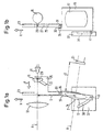
- FIG. 1a and 1b schematically show a side view and a front view of a sensor according to the invention, the scanning range a long range is set.
- This sensor has a transmitter 11, for example a light-emitting one Diode, for emitting a transmission light bundle along a transmission beam axis A.
- the transmitter 11 is on a not shown in the figures Fixed housing.
- a transmission optical system is arranged along the transmission beam axis A.
- This on the one hand has a round, transmission-fixed front lens 13, which is not shown in the front view of FIG. 1b.
- it On the other hand it has a substantially round, between the transmitter 11 and the Transmitting front lens 13 arranged and displaceable along the transmitting beam axis A. mounted focusing lens 15.
- a movable front reception lens is located below the transmission optics 17, which is fastened within a rectangular lens frame 19.
- the optical axis of the reception front lens 17 defines a reception beam axis B, at the end located within the sensor at a distance D a receiver 21 is arranged by the reception front lens 17. This distance D corresponds to the reception focal length.
- At the recipient 21 is a photosensitive photo element.
- the reception front lens 17 or the reception beam axis B is relative the transmission optics inclined so that the receive beam axis B Transmitting beam axis A at a certain triangulation angle and in intersects a crossing point, which in the illustration according to FIG. 1a is no longer shown, in one of the set sensing range of the sensor appropriate distance from the transmission front lens 13 and that Center of the set monitoring area defined.
- the center of the reception front lens 17 is at a distance S from the transmit beam axis A, which in the following is the basic distance of the triangulation is equated.
- the sensor shown in FIGS. 1a and 1b has an elongated, along a direction X aligned and slidable actuating pin 23 on. This is halfway up with a flat, parallel arranged adjacent to the transmission beam axis A and the transmission focusing lens 15 transmission-side guide link 25 and with a diagonal therein provided guide groove 27. Engages in the guide groove 27 Guide pin 29, the one facing the guide link 25 Side of the transmission focusing lens 15 is formed.
- the actuating pin 23 has a hinge hole at its lower end 31, into which a pivot pin 33 protrudes, which with one on the Molded top of the lens frame 19 of the receiving front lens 17 Triangular approach 35 is connected.
- the lens frame 19 laterally adjacent and within that of the transmit beam axis A and the receiving beam axis B spanned plane there is a flat, housing-mounted guide link on the reception side 37.
- This has on its front lens 17 facing Side on a curved guide groove 39.
- In this guide groove 39 protrudes from the lower region of the lens frame 19 Receiving front lens 17 molded guide pin 41 into it.
- the sensor according to the invention shown in FIGS. 1a and 1b serves for detecting objects that are within an adjustable Monitoring area.
- the transmitter 11 emits light along the transmission beam axis A.
- This transmission light is transmitted by means of the transmission focusing lens 15 and the transmission front lens 13 to form a transmission light beam focused so that an object is within the surveillance area located, struck by a concentrated transmitted light spot becomes.
- An object so acted upon by transmission light reflects or remits light, among other things, along the received beam axis B in Direction of the reception front lens 17.
- Light on the receiver 21, which corresponds to the received light signal can output electrical signal.
- This electrical signal can by means of evaluation electronics, not shown in the figures Determining the presence of an object in the surveillance area be evaluated, for example by exceeding a predetermined minimum signal is checked.
- the senor is at a maximum possible scanning distance set.
- a suitable triangulation angle is set to the receiver 21 fixed to the housing, under which the transmit beam axis A and the receive beam axis B cross at the desired distance (scanning distance) from the sensor, this triangulation angle due to the housing-fixed Mounting the receiver 21 exactly the base distance S shown in Fig. 1a equivalent.
- the sensor according to the invention allows different settings than in the 1a and 1b.
- the actuating pin 23 is in the direction X moves.
- the leadership backdrop 25 can only be moved in a straight line in the direction of the transmission beam axis A. stored so that a movement of the guide link 25 in the direction X the transmitting focusing lens 15 by means of the guide pin 29 to one Forces movement towards Y.
- a movement of the Transmitting focus lens 15 in the Y direction is the one emanating from the transmitter 11 Focused on a shorter and shorter scanning distance.
- the movement of the actuating pin 23 in the direction X a corresponding movement of the pivot pin 33 of the lens frame 19, so that the receiving front lens 17 a movement in the direction X performs.
- This crossing point of transmit beam axis A and receive beam axis B is therefore the new location of the monitoring area is set in principle.
- reception front lens 17 takes place due to the interaction of reception-side guide link 37 and guide pin 41 the lens frame 19 simultaneously with its rectilinear movement X one Tilting movement Z, in such a way that its optical axis is set at each Position on the light entry side towards the monitoring area and on the light exit side towards the receiver 21 is aligned.
- the curved course of the guide groove 39 is therefore chosen exactly that with every setting defined in principle by the basic distance S a monitoring area or a scanning range and a triangulation angle at the same time the alignment of the reception front lens 17 and the receiving focal length D is an optimal optical image of this Ensure monitoring area on the receiver 21.
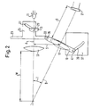
- the sensor shown in FIG. 2 is set to a minimum scanning range W.
- the reception front lens 17 is located at a small base distance S from the transmit beam axis A, and the transmit beam axis A and the received beam axis B close a comparatively large one Triangulation angle T on. Due to the position of the Transmission focusing lens 15 is the transmission light bundle along a point the transmitted beam axis A, which is exactly in one of the Distance W corresponding to the scanning distance from the transmission front lens 13. Light from an object that is at this distance W on the transmit beam axis A is located, due to the linear movement X and tilting movement Z of the reception front lens 17 or the one achieved thereby Setting the reception focal length D and the orientation of the Front receiving lens 17 optimally focused on the receiver 21.
- the sensor according to the invention thus enables any setting of scanning distances W within the two in FIGS. 1a and 1b and in the Fig. 2 shown extremes.
- the actuating mechanism accordingly, in particular the course of the guide grooves 27, 39, it is possible to optimally map for each set scanning range W. both the transmission light on the surveillance area and the Reaching reception light on the receiver 21.
- the receiver 21 is arranged that the receiving light beam has its photosensitive surface at the between the two extreme settings of the sensor mentioned Sensing ranges applied in a symmetrical angular range.
- the receiver can compensate 21 with higher intensity also be arranged so that it is exactly at the maximum remote setting of the sensor with the greatest possible intensity, i.e. essentially in parallel to the surface normal of its light-sensitive surface, receiving light becomes.
- the resolution-optimized scanning range setting of the sensor is easy and space-saving construction achieved.
- the transmit focusing lens 15, the receiving front lens 17, the actuating pin 23 and the receiving end Guide link 37 only guide elements fixed to the housing are required, which a linear movement of the actuating pin 23 in the direction X or the transmit focusing lens 15 along the transmit beam axis A guarantee.
- the actuating pin 23 is not directly articulated with the lens frame 19 to connect the receiving front lens 17, but one at the To provide actuating pin 23 molded guide link, by means of which the reception front lens 17 is indirectly caused to move, corresponding to that shown in the figures for the transmission focusing lens 15 Mechanism.
Landscapes
- Engineering & Computer Science (AREA)
- Physics & Mathematics (AREA)
- Computer Networks & Wireless Communication (AREA)
- General Physics & Mathematics (AREA)
- Radar, Positioning & Navigation (AREA)
- Remote Sensing (AREA)
- Electromagnetism (AREA)
- Measurement Of Optical Distance (AREA)
- Length Measuring Devices By Optical Means (AREA)
- Geophysics And Detection Of Objects (AREA)
Claims (5)
- Capteur optoélectronique pour reconnaítre des objets à l'intérieur d'une zone de surveillance limitée dans l'espace et réglable, comportant
un émetteur (11) pour émettre un faisceau de lumière d'émission le long d'un axe d'injection d'émission (A) en direction de la zone de surveillance,
un récepteur (21) pour détecter de la lumière qui est réfléchie ou réémise le long d'un axe d'injection de réception (B) par un objet situé à l'intérieur de la zone de surveillance,
ainsi qu'une lentille de focalisation d'émission (15) associée à l'émetteur (11) et une lentille frontale de réception (17) associée au récepteur (21),
l'émetteur (11) et le récepteur (21) étant chacun agencés de manière stationnaire à l'intérieur d'un boítier, et
la lentille de focalisation d'émission (15) et la lentille frontale de réception (17) pouvant être déplacées par rapport au boítier à l'aide d'un moyen de réglage,
caractérisé en ce que
lors de l'actionnement du moyen de réglage, le tracé du mouvement de la lentille de focalisation d'émission (15) peut être commandé par un moyen de guidage côté émission, et le tracé du mouvement de la lentille frontale de réception (17) peut être commandé simultanément par un moyen de guidage côté réception, de telle sorte quepar le mouvement de la lentille de focalisation d'émission (15) peut être modifiée la distance entre la lentille de focalisation d'émission (15) et l'émetteur (11), etpar le mouvement de la lentille frontale de réception (17) peuvent être modifiés l'angle de triangulation (T) entre l'axe d'injection d'émission (A) et l'axe d'injection de réception (B), la distance de base (S) entre l'axe d'injection d'émission (A) et l'axe d'injection de réception (B) à l'emplacement du capteur, la distance (D) entre la lentille frontale de réception (17) et le récepteur (21), et l'alignement de la lentille frontale de réception (17). - Capteur optoélectronique selon la revendication 1, caractérisé en ce qu'en actionnant le moyen de réglage, l'angle de triangulation (T), la distance de base (S), la distance focale d'émission, la distance focale de réception (D) et l'alignement de la lentille frontale de réception (17) peuvent être modifiés de telle sorte que
dans chaque position du moyen de réglage, le faisceau de lumière d'émission de l'émetteur (11) est focalisé sensiblement sur la zone de surveillance, et/ou
dans chaque position du moyen de réglage, la lumière, qui est réfléchie ou réémise le long de l'axe d'injection de réception (B) par un objet se trouvant à l'intérieur de la zone de surveillance, est focalisée sensiblement sur le récepteur (21). - Capteur optoélectronique selon l'une des revendications précédentes, caractérisé en ce que
le moyen de réglage est relié en particulier de manière articulée à la lentille de focalisation d'émission (15) ou à une monture de lentille sur laquelle est fixée la lentille de focalisation d'émission (15), et/ou
en ce que le moyen de réglage est relié en particulier de manière articulée à la lentille frontale de réception (17) ou à une monture de lentille sur laquelle est fixée la lentille frontale de réception (17). - Capteur optoélectronique selon l'une des revendications précédentes, caractérisé en ce que le moyen de réglage présente une goupille d'actionnement (23).
- Capteur optoélectronique selon l'une des revendications précédentes, caractérisé en ce que le moyen de guidage côté émission ou le moyen de guidage côté réception présente une coulisse (25, 37) avec un élément de guidage (27, 39), dans lequel fait saillie un élément d'engagement (29, 41) associé, dans lequel
soit la coulisse (37) est agencée solidaire du boítier et l'élément d'engagement (41) est relié à la lentille (17) associée au moyen de guidage ou à une monture de lentille (19) sur laquelle est fixée la lentille (17), soit la coulisse est reliée à la lentille associée au moyen de guidage ou à une monture de lentille sur laquelle est fixée la lentille associée, et l'élément d'engagement est agencé solidaire du boítier, ou
soit la coulisse (25) est reliée au moyen de réglage (23) et l'élément d'engagement (29) est relié à la lentille (15) associée au moyen de guidage ou à une monture de lentille sur laquelle est fixée la lentille (15) associée, soit la coulisse est reliée à la lentille associée au moyen de guidage ou à une monture de lentille sur laquelle est fixée la lentille associée, et l'élément d'engagement est relié au moyen de réglage.
Applications Claiming Priority (2)
| Application Number | Priority Date | Filing Date | Title |
|---|---|---|---|
| DE19804803 | 1998-02-06 | ||
| DE19804803A DE19804803A1 (de) | 1998-02-06 | 1998-02-06 | Optoelektronischer Sensor |
Publications (3)
| Publication Number | Publication Date |
|---|---|
| EP0935142A2 EP0935142A2 (fr) | 1999-08-11 |
| EP0935142A3 EP0935142A3 (fr) | 2000-04-05 |
| EP0935142B1 true EP0935142B1 (fr) | 2004-03-10 |
Family
ID=7856884
Family Applications (1)
| Application Number | Title | Priority Date | Filing Date |
|---|---|---|---|
| EP98124878A Expired - Lifetime EP0935142B1 (fr) | 1998-02-06 | 1998-12-30 | Capteur optoélectronique |
Country Status (2)
| Country | Link |
|---|---|
| EP (1) | EP0935142B1 (fr) |
| DE (2) | DE19804803A1 (fr) |
Families Citing this family (4)
| Publication number | Priority date | Publication date | Assignee | Title |
|---|---|---|---|---|
| JPH11352434A (ja) | 1998-06-08 | 1999-12-24 | Sankyo Seiki Mfg Co Ltd | ビーム走査装置 |
| DE10006321A1 (de) * | 2000-02-12 | 2001-08-23 | Daimler Chrysler Ag | Verfahren zur Herstellung einer optischen Überwachungseinrichtung sowie Optik und Optikaufnehmer zur Durchführung des Verfahrens |
| US6611318B2 (en) | 2001-03-23 | 2003-08-26 | Automatic Timing & Controls, Inc. | Adjustable mirror for collimated beam laser sensor |
| ES2346376T3 (es) | 2008-04-22 | 2010-10-14 | Sick Ag | Dispositivo de identificacion para la deteccion lineal de un codigo dispuesto en un plano del objeto. |
Family Cites Families (5)
| Publication number | Priority date | Publication date | Assignee | Title |
|---|---|---|---|---|
| DE2456248A1 (de) * | 1974-11-28 | 1976-08-12 | Sick Optik Elektronik Erwin | Einrichtung zur feststellung der anwesenheit eines gegenstandes in einem erkennungsgebiet |
| JPS5931814B2 (ja) * | 1978-06-19 | 1984-08-04 | オムロン株式会社 | 反射形光電スイッチ |
| US4412129A (en) * | 1981-04-01 | 1983-10-25 | Eaton Corporation | Adjustable photoelectric detector head for solid state limit switch |
| DE4013743A1 (de) * | 1990-04-28 | 1991-11-07 | Klaschka Ind Elektronik | Optischer abstandsschalter |
| IT1283729B1 (it) * | 1996-04-12 | 1998-04-30 | Datologic S P A | Dispositivo elettroottico per rilevare la presenza di un corpo a distanza regolabile con soppressione di sfondo |
-
1998
- 1998-02-06 DE DE19804803A patent/DE19804803A1/de not_active Withdrawn
- 1998-12-30 EP EP98124878A patent/EP0935142B1/fr not_active Expired - Lifetime
- 1998-12-30 DE DE59810954T patent/DE59810954D1/de not_active Expired - Lifetime
Also Published As
| Publication number | Publication date |
|---|---|
| DE59810954D1 (de) | 2004-04-15 |
| EP0935142A2 (fr) | 1999-08-11 |
| DE19804803A1 (de) | 1999-08-12 |
| EP0935142A3 (fr) | 2000-04-05 |
Similar Documents
| Publication | Publication Date | Title |
|---|---|---|
| DE69705575T2 (de) | Elektro-optisches Gerät zur Erkennung der Anwesenheit eines Gegenstands in einstellbarem Abstand, mit Hintergrundausblendung | |
| DE3513671C3 (de) | Lichttaster | |
| EP2834661A1 (fr) | Dispositif de détection optoélectronique, en particulier scanneur à laser, comportant une unité de réception adaptée pour une réduction optimisée du niveau de réception | |
| EP2202533A1 (fr) | Dispositif de détection | |
| EP1395853A1 (fr) | Dispositif de mesure optique de distances | |
| EP1515157A1 (fr) | Dispositif de détection optoélectronique | |
| EP2482094A1 (fr) | Capteur optoélectronique mesurant l'éloignement et procédé de détection d'objet | |
| DE19860464C2 (de) | Laserentfernungsmeßgerät für große Meßbereiche | |
| DE102015105263A1 (de) | Optoelektronischer Sensor und Verfahren zur Erfassung von Objekten in einem Überwachungsbereich | |
| DE10247136A1 (de) | Schutzvorrichtung zur Überwachung eines mit einem Bauteil zu bewegenden Schutzbereichs | |
| EP0935142B1 (fr) | Capteur optoélectronique | |
| EP2040097B1 (fr) | Capteur optoélectronique | |
| EP1729108B1 (fr) | Dispositif de mesure de concentration de particules et son procédé de mesure | |
| DE202008011469U1 (de) | Optoelektronischer Sensor | |
| EP3486615B1 (fr) | Dispositif de fonctionnement pourvu d'élément de fonctionnement focalisant | |
| DE102016213980A1 (de) | Optische Anordnung für ein LiDAR-System, LiDAR-System und Arbeitsvorrichtung | |
| DE4222659C2 (de) | Abtastendes Hinderniswarngerät | |
| DE102005041998B4 (de) | Verfahren zur Justage eines abbildenden Elements sowie Messgerät justiert nach einem derartigen Verfahren | |
| EP3939774B1 (fr) | Fabrication d'un capteur optoélectronique | |
| DE4217696C2 (de) | Optoelektronischer Signalgeber | |
| DE102011009158B3 (de) | Optisches Gasdetektorsystem | |
| EP2843446B1 (fr) | Capteur optique | |
| DE102013020572B4 (de) | Optoelektronischer Sensor | |
| DE3223713A1 (de) | Fotografische oder kinematografische kamera mit einem objektiv und einem aktiven entfernungsmesser | |
| DE20117499U1 (de) | Optischer Sensor |
Legal Events
| Date | Code | Title | Description |
|---|---|---|---|
| PUAI | Public reference made under article 153(3) epc to a published international application that has entered the european phase |
Free format text: ORIGINAL CODE: 0009012 |
|
| AK | Designated contracting states |
Kind code of ref document: A2 Designated state(s): CH DE IT LI |
|
| AX | Request for extension of the european patent |
Free format text: AL;LT;LV;MK;RO;SI |
|
| PUAL | Search report despatched |
Free format text: ORIGINAL CODE: 0009013 |
|
| AK | Designated contracting states |
Kind code of ref document: A3 Designated state(s): AT BE CH CY DE DK ES FI FR GB GR IE IT LI LU MC NL PT SE |
|
| AX | Request for extension of the european patent |
Free format text: AL;LT;LV;MK;RO;SI |
|
| RIC1 | Information provided on ipc code assigned before grant |
Free format text: 7G 01S 7/481 A, 7G 01S 17/02 B, 7G 01S 17/46 B, 7G 01S 7/497 B |
|
| 17P | Request for examination filed |
Effective date: 20000516 |
|
| AKX | Designation fees paid |
Free format text: CH DE IT LI |
|
| 17Q | First examination report despatched |
Effective date: 20020610 |
|
| GRAP | Despatch of communication of intention to grant a patent |
Free format text: ORIGINAL CODE: EPIDOSNIGR1 |
|
| GRAS | Grant fee paid |
Free format text: ORIGINAL CODE: EPIDOSNIGR3 |
|
| GRAA | (expected) grant |
Free format text: ORIGINAL CODE: 0009210 |
|
| AK | Designated contracting states |
Kind code of ref document: B1 Designated state(s): CH DE IT LI |
|
| REG | Reference to a national code |
Ref country code: CH Ref legal event code: EP |
|
| REF | Corresponds to: |
Ref document number: 59810954 Country of ref document: DE Date of ref document: 20040415 Kind code of ref document: P |
|
| PLBE | No opposition filed within time limit |
Free format text: ORIGINAL CODE: 0009261 |
|
| STAA | Information on the status of an ep patent application or granted ep patent |
Free format text: STATUS: NO OPPOSITION FILED WITHIN TIME LIMIT |
|
| 26N | No opposition filed |
Effective date: 20041213 |
|
| PGFP | Annual fee paid to national office [announced via postgrant information from national office to epo] |
Ref country code: IT Payment date: 20071222 Year of fee payment: 10 |
|
| PG25 | Lapsed in a contracting state [announced via postgrant information from national office to epo] |
Ref country code: IT Free format text: LAPSE BECAUSE OF NON-PAYMENT OF DUE FEES Effective date: 20081230 |
|
| PGFP | Annual fee paid to national office [announced via postgrant information from national office to epo] |
Ref country code: CH Payment date: 20131218 Year of fee payment: 16 |
|
| PGFP | Annual fee paid to national office [announced via postgrant information from national office to epo] |
Ref country code: DE Payment date: 20131217 Year of fee payment: 16 |
|
| REG | Reference to a national code |
Ref country code: DE Ref legal event code: R119 Ref document number: 59810954 Country of ref document: DE |
|
| REG | Reference to a national code |
Ref country code: CH Ref legal event code: PL |
|
| PG25 | Lapsed in a contracting state [announced via postgrant information from national office to epo] |
Ref country code: CH Free format text: LAPSE BECAUSE OF NON-PAYMENT OF DUE FEES Effective date: 20141231 Ref country code: LI Free format text: LAPSE BECAUSE OF NON-PAYMENT OF DUE FEES Effective date: 20141231 Ref country code: DE Free format text: LAPSE BECAUSE OF NON-PAYMENT OF DUE FEES Effective date: 20150701 |