EP0935144B1 - Projet d'évaluation pour une méthode de télémètrie - Google Patents
Projet d'évaluation pour une méthode de télémètrie Download PDFInfo
- Publication number
- EP0935144B1 EP0935144B1 EP99100847A EP99100847A EP0935144B1 EP 0935144 B1 EP0935144 B1 EP 0935144B1 EP 99100847 A EP99100847 A EP 99100847A EP 99100847 A EP99100847 A EP 99100847A EP 0935144 B1 EP0935144 B1 EP 0935144B1
- Authority
- EP
- European Patent Office
- Prior art keywords
- signal
- digital signal
- pulse
- wave
- mean
- Prior art date
- Legal status (The legal status is an assumption and is not a legal conclusion. Google has not performed a legal analysis and makes no representation as to the accuracy of the status listed.)
- Expired - Lifetime
Links
Images

Classifications
-
- G—PHYSICS
- G01—MEASURING; TESTING
- G01S—RADIO DIRECTION-FINDING; RADIO NAVIGATION; DETERMINING DISTANCE OR VELOCITY BY USE OF RADIO WAVES; LOCATING OR PRESENCE-DETECTING BY USE OF THE REFLECTION OR RERADIATION OF RADIO WAVES; ANALOGOUS ARRANGEMENTS USING OTHER WAVES
- G01S17/00—Systems using the reflection or reradiation of electromagnetic waves other than radio waves, e.g. lidar systems
- G01S17/02—Systems using the reflection of electromagnetic waves other than radio waves
- G01S17/06—Systems determining position data of a target
- G01S17/08—Systems determining position data of a target for measuring distance only
- G01S17/10—Systems determining position data of a target for measuring distance only using transmission of interrupted, pulse-modulated waves
-
- G—PHYSICS
- G01—MEASURING; TESTING
- G01S—RADIO DIRECTION-FINDING; RADIO NAVIGATION; DETERMINING DISTANCE OR VELOCITY BY USE OF RADIO WAVES; LOCATING OR PRESENCE-DETECTING BY USE OF THE REFLECTION OR RERADIATION OF RADIO WAVES; ANALOGOUS ARRANGEMENTS USING OTHER WAVES
- G01S7/00—Details of systems according to groups G01S13/00, G01S15/00, G01S17/00
- G01S7/48—Details of systems according to groups G01S13/00, G01S15/00, G01S17/00 of systems according to group G01S17/00
- G01S7/483—Details of pulse systems
- G01S7/486—Receivers
- G01S7/4865—Time delay measurement, e.g. time-of-flight measurement, time of arrival measurement or determining the exact position of a peak
- G01S7/4866—Time delay measurement, e.g. time-of-flight measurement, time of arrival measurement or determining the exact position of a peak by fitting a model or function to the received signal
-
- G—PHYSICS
- G01—MEASURING; TESTING
- G01S—RADIO DIRECTION-FINDING; RADIO NAVIGATION; DETERMINING DISTANCE OR VELOCITY BY USE OF RADIO WAVES; LOCATING OR PRESENCE-DETECTING BY USE OF THE REFLECTION OR RERADIATION OF RADIO WAVES; ANALOGOUS ARRANGEMENTS USING OTHER WAVES
- G01S7/00—Details of systems according to groups G01S13/00, G01S15/00, G01S17/00
- G01S7/48—Details of systems according to groups G01S13/00, G01S15/00, G01S17/00 of systems according to group G01S17/00
- G01S7/483—Details of pulse systems
- G01S7/486—Receivers
- G01S7/4868—Controlling received signal intensity or exposure of sensor
Definitions
- the invention relates to a method and a device for Determining the distance between a distance sensor and an object.
- the transit time measurement method becomes a predetermined Start time sent a light pulse and at the same time Counter triggered.
- the light pulse is applied to an object whose Distance to be determined, reflected and reflected Light pulse is detected by a receiver and by a detected analog detection electronics.
- An object of the present invention is a Determine distance determination method, the low Hardeware effort a high measurement accuracy and a provides sufficient signal-to-noise ratio.
- the digitization of the received signal has to Episode that the temporal resolution of the digitized Signal limited by the sampling frequency f2 of the A / D converter becomes.
- the distance resolution is now increased by not only one but several - namely k - wave pulse transit time values T1, T2, ..., Tk and from these k runtime values the arithmetic mean T is calculated. This averaging increases the distance resolution because the sampling times through the A / D converter time regardless of the times of Transmission of the individual wave pulses are.
- the asynchronous Sampling causes, when actually identical Pulse transit times of different wave pulses (i.e. constant distance) nevertheless a stochastic distribution of measured transit times T1, T2, ..., Tk is recorded.
- a stochastic distribution of measured transit times T1, T2, ..., Tk is recorded.
- stochastically distributed around the actual runtime Running times T1, T2, ..., Tk will be the resolution of the measurement then increased by the factor 2ROOT k.
- Because of this through a Software solution will increase the measurement resolution on the other hand, with respect to the hardware requirements cost-effective implementation of the method according to the invention allows. The reason for this is to be seen in that due to the invention achieved by calculation Resolution increase to achieve a predetermined, in the Practice required measurement resolution of the overall system now a correspondingly slower and thus cheaper A / D converter can be used.
- n is chosen between 10 and 100. Since the signal-to-noise ratio improvement is proportional to ⁇ n, this provides a 3.16 to 10-fold increase in signal-to-noise ratio.
- R (t) is a predetermined digitized reference signal with m-times higher temporal resolution than Z (t) or ⁇ Z (t)> and where m is an integer number with m> 1, and
- m is between 2 and 10.
- m is between 2 and 10.
- the controller can do this be done that the gain is increased when the reflected total intensity or even the maximum Intensity falls below a predetermined value.
- From several determined distance values T can in preferably also information about a Relative movement between the object and the sensor won become. This is done in such a way that the obtained Distance values D are stored in a memory and off several distance values D by differentiation after the Time continuously the relative speed between Object and distance sensor is determined.
- the second object is achieved by a device according to the characterizing features of claim 11 solved.
- the senor can be of any type.
- An especially suitable for use in motor vehicles, powerful embodiment of the device according to the invention Characterized by the fact that the sensor as a transmitter Includes infrared laser diode.
- the A / D converter is a buffer downstream, the digital signal continuously stores and from which the evaluation circuit the digital Receives signal by reading the buffer.
- One FIFO is particularly suitable for this because its read-in clock regardless of his output tact and he is thus to Coupling of asynchronous systems is suitable.
- a device for distance measurement has a Microcontroller 1, which includes a timer 2, which an electrical pulse signal 3 to a drive circuit 4th for an IR laser diode 5 outputs.
- the IR laser diode 5 is powerful enough to allow a wide measuring range.
- the light pulses 6 emitted by the IR laser diode 5 are reflected on an object 7 and the reflected Light pulses 8 are from a receiver, in the form of a fast photodiode 9 is realized, added.
- the emitted light pulses 6 have a short pulse duration from about 20 to 50 ns, even at short distances in the range of 2 m an accurate distance measurement too enable.
- the output from the photodiode 9 received signal 10 is an amplifier 11 and after a gain and optionally additionally provided signal shaping a A / D converter 12 is provided.
- the A / D converter 12 samples the received signal 10 continuously from a frequency f2 and processes it into a digital signal Z (t), the is denoted by reference numeral 13 in Fig. 1.
- the digital signal Z (t) is stored in a FIFO (First-In-First-Out) Buffer memory 14 is stored and is at the output of the FIFO buffer memory 14 the microcontroller 1 available.
- the microcontroller 1 can be independent of the sampling frequency f2 of the A / D converter, the input-side data input certainly, with its slower frequency (for example frequency f1) to those in the FIFO buffer memory 14 stored data.
- microcontroller 1 is connected via a control line 15 with the amplifier 11 and via a message line 16 with the A / D converter 12 in conjunction.
- step S1 first by means of in the Microcontroller 1 integrated pulse generator 2 the Pulse signal 3 of the frequency f1 generated by the IR laser diode 5 is controlled.
- the IR laser diode 5 transmits then a predetermined sequence of light pulses.
- Step S2 becomes the latch 14 with those of the A / D converter 12 digitized receive data filled.
- the Data enters at a frequency f2.
- the im Latches 14 are stored data in step S3 read from the microcontroller 1 and either immediately further processed or first in another Memory area of the microcontroller 1 for later Processing stored.
- step S4 the Signal averaging step to improve signal-to-noise Ratio. This happens through a n-times Summation of each received with respect to a light pulse Signal data sequences Z1 (t), ..., Zn (t) in step S4 and by a subsequent averaging in step S5, in the the average digital signal ⁇ Z (t)> is calculated.
- each Transmission of a light pulse is the A / D converter 12 of the microcontroller 1 via the message line 16th communicated.
- the A / D converter 12 generates at each Message a particular, previously set binary Signal that serves as a brand.
- the brands thus separate in digitized signal Z (t) the individual, one each Light pulse associated signal sequences Z1 (t), ..., Zn (t).
- This method is based on the fact that the buffer 14 the order of cached data is unchanged leaves.
- step S5 In addition to the averaging is in step S5 also checked whether the average digital signal ⁇ Z (t)> one for the further signal processing sufficient signal-to-noise Ratio. If this is not the case, the Process returns to step S1 and it will be another episode generated by light pulses, with which the signal averaging in the steps S4 and S5 is continued. At a sufficient signal-to-noise ratio of the middle Signal ⁇ Z (t)>, the process goes to step S6 and Step S9 via.
- step S6 the maximum amplitude becomes integral Signal intensity as a measure of the total backscatter of the Light pulses and the signal-to-noise ratio determined.
- step S7 if necessary in Microcontroller 1 integrated PID controller supplied to the via the control line 15 in step S8, the gain of Amplifier 11 regulates.
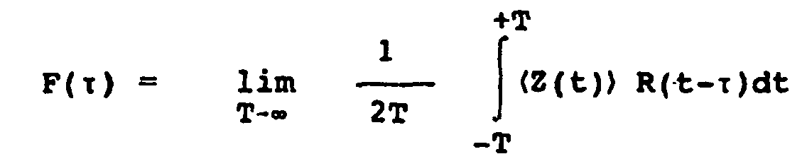
- Steps S9 and S10 relate to the correlation of middle digital signal ⁇ Z (t)> with a discrete Reference signal R (t), for example in the form of a Gaussian pulse can be realized.
- the discrete reference signal R (t) has an M-times higher temporal resolution than the signal ⁇ Z (t)>, the time resolution by f2 given is.
- step S9 the correlation function F ( ⁇ ) is calculated numerically in step S9 according to the following relationship:
- step S10 the running time T1 as the time of maximum correlation between the reference signal R (t) and the mean digital signal ⁇ Z (t)> determined.
- the case Distance information T1 obtained has a m-fold higher temporal resolution with respect to the digital signal Z (t) and the middle digital signal ⁇ Z (t)>.
- the time averaging according to the invention is performed in steps S11 and S12 performed.
- step S11 first of Value T1 stored and then moved to step S12.
- step S12 it is checked whether the k-times summation already completed, which at the first pass (i.e. T1) is obviously not the case yet. The whole previously described process is then repeated and it In this way, the pulse transit times T2, T3, etc. determined and summed up in step 11.
- At summation of last pulse duration Tk in step 11 then becomes in step S12 canceled the recursion and by dividing the summed pulse transit times (T1 + T2 + ... + Tk) by k der temporal mean T determined.
- the value T then becomes the distance value D determined.
- step S13 are determined in the manner described Time values T collected and in step S14 is from these Values a relative velocity between sensor and Object calculated.
- step S15 the output of the determined relative speed values.
Landscapes
- Engineering & Computer Science (AREA)
- Physics & Mathematics (AREA)
- Computer Networks & Wireless Communication (AREA)
- General Physics & Mathematics (AREA)
- Radar, Positioning & Navigation (AREA)
- Remote Sensing (AREA)
- Electromagnetism (AREA)
- Optical Radar Systems And Details Thereof (AREA)
- Radar Systems Or Details Thereof (AREA)
- Measurement Of Velocity Or Position Using Acoustic Or Ultrasonic Waves (AREA)
Claims (15)
- Procédé pour déterminer la distance entre un capteur de distance et un objet (7), dans lequel on applique à un émetteur (5) du capteur de distance un signal électrique impulsionnel (3) à une première fréquence prédéterminée f1, l'émetteur (5) émet une impulsion d'onde (6) à chaque apparition d'une impulsion électrique, les impulsions d'onde (6) sont réfléchies par l'objet (7), un récepteur (9) du capteur de distance reçoit les impulsions d'onde réfléchies (8) et délivre un signal électrique analogique de réception (10), le signal électrique analogique de réception (10) étant échantillonné en continu par un convertisseur A/N (12) à une deuxième fréquence f2, avec f2 > f1, et converti en un signal numérique Z(t) (13), et dans lequel le signal numérique Z(t) (13) est traité de la manière suivante afin de déterminer une valeur de distance D :a) Traitement du signal numérique Z(t) (13) obtenu pour une plusieurs impulsions d'onde (6) émises en fonction de plusieurs, à savoir n impulsions d'onde afin de déterminer un premier temps de parcours de l'impulsion d'onde T1, n étant un nombre entier, avec n > 1,i) en décomposant le signal numérique Z(t) (13) en n séquences de signal se suivant dans le temps Z1 (t), ..., Zn(t),ii) en calculant un signal numérique moyen <Z (t)> par formation d'une moyenne sur les n séquences de signal, etiii) en utilisant le signal numérique moyen <Z (t)> pour déterminer le premier temps de parcours de l'impulsion d'onde T1,b) Répétition k fois de l'étape a) afin de déterminer les temps de parcours du total de k impulsions d'onde T1, T2, ..., Tk, k étant un nombre entier avec k > 1,c) Calcul d'un temps de parcours moyen de l'impulsion d'onde T = (T1 + T2 + ... + Tk) /k, etd) Calcul de la valeur de distance D suivant D = v*T/2, où v est la vitesse de propagation des impulsions d'onde,e) Détermination du rapport signal/bruit à partir du signal numérique moyen <Z (t)> dans l'étape de travail aii) et génération d'une autre séquence de signaux électriques impulsionnels (3) lorsque le rapport signal/bruit n'est pas suffisant pour poursuivre le traitement du signal.
- Procédé selon la revendication 1, caractérisé en ce que n a une valeur comprise entre 10 et 100.
- Procédé selon la revendication 1 ou la revendication 2, caractérisé en ce que le traitement du signal numérique Z(t) à l'étape a) ou du signal numérique moyen <Z (t)> à l'étape 2a) comprend les étapes suivantes :où R(t) est un signal de référence discrétisé prédéterminé ayant une résolution temporelle m fois supérieure à celle de Z(t) ou <Z (t)> et m est un nombre entier, avec m > 1, et détermination du temps de parcours T1 de l'impulsion d'onde comme étant le temps auquel la fonction de corrélation F(i) est maximale.Calcul d'une fonction de corrélation F (τ) suivant l'équationou

- Procédé selon la revendication 3, caractérisé en ce que le signal de référence discrétisé R(t) est une fonction gaussienne.
- Procédé selon la revendication 3 ou la revendication 4, caractérisé en ce que m a une valeur comprise entre 2 et 10.
- Procédé selon l'une des revendications précédentes, caractérisé en ce que les impulsions d'onde sont des impulsions lumineuses et en ce que les impulsions ont une durée de 20 à 50 ns.
- Procédé selon l'une des revendications précédentes, caractérisé en ce que f1 se situe dans la plage de 1 kHz à 10 kHz.
- Procédé selon l'une des revendications précédentes, caractérisé en ce que f2 est égal à environ 40 MHz.
- Procédé selon l'une des revendications précédentes, caractérisé en ce que l'on détermine à partir du signal numérique moyen <Z (t)> l'intensité totale réfléchie et/ou l'intensité maximale et en ce que l'un au moins de ces paramètres et/ou le rapport signal/bruit est prévu pour commander l'amplification d'un amplificateur (11) qui amplifie le signal de réception (10).
- Procédé selon l'une des revendications précédentes, caractérisé en ce que les valeurs de distance D obtenues sont stockées en continu dans une mémoire et en ce que, par différenciation dans le temps à partir de plusieurs valeurs de distance D, on détermine en continu la vitesse relative entre l'objet (7) et le capteur de distance.
- Dispositif pour déterminer une distance entre un capteur de distance et un objet (7), avec un générateur d'impulsion (2) pour produire un signal électrique impulsionnel (3) à une première fréquence prédéterminée f1, un émetteur (5) qui reçoit le signal impulsionnel (3) et qui délivre une impulsion d'onde (6) à chaque apparition d'une impulsion électrique, un récepteur (9) qui reçoit les impulsions d'onde (8) réfléchies par l'objet (7) et délivre ensuite un signal électrique analogique de réception (10), avec un convertisseur A/N (12) qui échantillonne en continu le signal électrique analogique de réception (10) à une fréquence f2, avec f2 > f1, et le convertit en un signal numérique Z(t) (13), caractérisé par un circuit de traitement dans lequel plusieurs, c'est-à-dire n impulsions d'onde sont décomposées k fois en n séquences de signal Z1 (t), ..., Zn(t) se suivant dans le temps, n étant un nombre entier, avec n > 1, afin de déterminer un premier temps de parcours d'impulsion d'onde T1 et qui, par formation de la moyenne, calcule un signal numérique moyen <Z (t)> qui est utilisé pour déterminer le premier temps de parcours d'impulsion d'onde T1, T2, ..., Tk, où k est un nombre entier, avec k > 1, et un temps de parcours d'impulsion d'onde moyen T = (T1 + T2 + ... + Tk)/k et la valeur de distance D est calculée suivant D =v *T/2, où v est la vitesse de propagation des impulsions d'onde, et le rapport signal/bruit est déterminé à partir du signal numérique moyen <Z (t)> afin de générer une autre séquence de signaux électriques impulsionnels (3) lorsque le rapport signal/bruit n'est pas suffisant pour la suite du traitement du signal.
- Dispositif selon la revendication 11, caractérisé en ce que l'émetteur est une diode laser à infrarouge (5).
- Dispositif selon la revendication 11 ou la revendication 12, caractérisé en ce que le convertisseur A/N (12) est relié en amont à une mémoire intermédiaire (14) qui stocke en continu le signal numérique Z(t) (13) et en ce que le circuit de traitement (1) extrait le signal numérique Z(t) (13) en lisant la mémoire intermédiaire (14).
- Dispositif selon la revendication 13, caractérisé en ce que la mémoire intermédiaire (14) est une mémoire FIFO.
- Dispositif selon l'une des revendications 11 à 14, caractérisé en ce qu'un amplificateur (11) avec une amplification variable, commandée par le circuit de traitement (1), est câblé entre le récepteur (9) et le convertisseur A/N (12).
Applications Claiming Priority (2)
| Application Number | Priority Date | Filing Date | Title |
|---|---|---|---|
| DE19804958A DE19804958A1 (de) | 1998-02-07 | 1998-02-07 | Auswertekonzept für Abstandsmeßverfahren |
| DE19804958 | 1998-02-07 |
Publications (3)
| Publication Number | Publication Date |
|---|---|
| EP0935144A2 EP0935144A2 (fr) | 1999-08-11 |
| EP0935144A3 EP0935144A3 (fr) | 2000-03-29 |
| EP0935144B1 true EP0935144B1 (fr) | 2005-11-16 |
Family
ID=7856991
Family Applications (1)
| Application Number | Title | Priority Date | Filing Date |
|---|---|---|---|
| EP99100847A Expired - Lifetime EP0935144B1 (fr) | 1998-02-07 | 1999-01-19 | Projet d'évaluation pour une méthode de télémètrie |
Country Status (4)
| Country | Link |
|---|---|
| US (1) | US6259515B1 (fr) |
| EP (1) | EP0935144B1 (fr) |
| DE (2) | DE19804958A1 (fr) |
| ES (1) | ES2252878T3 (fr) |
Families Citing this family (16)
| Publication number | Priority date | Publication date | Assignee | Title |
|---|---|---|---|---|
| AT406093B (de) * | 1998-05-19 | 2000-02-25 | Perger Andreas Dr | Verfahren zur optischen entfernungsmessung |
| DE10343175A1 (de) * | 2003-09-18 | 2005-04-14 | Robert Bosch Gmbh | Verfahren zur Abstandsmessung und Messeinrichtung hierzu |
| WO2008154736A1 (fr) * | 2007-06-18 | 2008-12-24 | Leddartech Inc. | Système d'éclairage à fonctions d'assistance au conducteur |
| US8242476B2 (en) * | 2005-12-19 | 2012-08-14 | Leddartech Inc. | LED object detection system and method combining complete reflection traces from individual narrow field-of-view channels |
| EP2158579B1 (fr) * | 2007-06-18 | 2014-10-15 | Leddartech Inc. | Système d'éclairage avec fonctions de gestion de trafic |
| US7640122B2 (en) * | 2007-11-07 | 2009-12-29 | Institut National D'optique | Digital signal processing in optical systems used for ranging applications |
| EP2232462B1 (fr) * | 2007-12-21 | 2015-12-16 | Leddartech Inc. | Système et procédé de gestion de stationnement utilisant un système d'éclairage |
| WO2009079789A1 (fr) | 2007-12-21 | 2009-07-02 | Leddartech Inc. | Procédés et systèmes de détection et de télémétrie |
| DE202008004438U1 (de) | 2008-03-31 | 2008-06-12 | Herbert Waldmann Gmbh & Co. Kg | Bestrahlungsgerät insbesondere für die Lichttherapie |
| WO2009121181A1 (fr) * | 2008-04-04 | 2009-10-08 | Leddartech Inc. | Dispositif et procédé de mesure du niveau optique |
| CN102959599B (zh) | 2009-12-22 | 2015-07-15 | 莱达科技股份有限公司 | 用于交通检测的主动3d监控系统 |
| US8908159B2 (en) | 2011-05-11 | 2014-12-09 | Leddartech Inc. | Multiple-field-of-view scannerless optical rangefinder in high ambient background light |
| EP2721593B1 (fr) | 2011-06-17 | 2017-04-05 | Leddartech Inc. | Système et procédé de détection latérale et de caractérisation de circulation |
| US9235988B2 (en) | 2012-03-02 | 2016-01-12 | Leddartech Inc. | System and method for multipurpose traffic detection and characterization |
| WO2016038536A1 (fr) | 2014-09-09 | 2016-03-17 | Leddartech Inc. | Discrétisation de zone de détection |
| US11187792B2 (en) * | 2016-03-01 | 2021-11-30 | Elmos Semiconductor Se | Device for converting a temporal delay of a signal transmitted between a transmitter and a receiver |
Family Cites Families (11)
| Publication number | Priority date | Publication date | Assignee | Title |
|---|---|---|---|---|
| US3503680A (en) * | 1967-03-31 | 1970-03-31 | Perkin Elmer Corp | Range measuring system |
| US3645624A (en) * | 1970-07-07 | 1972-02-29 | Perkin Elmer Corp | Range-measuring method and apparatus |
| CA1028039A (fr) * | 1974-12-19 | 1978-03-14 | John N. Barry | Moyen de determiner la distance ou l'intervalle de temps dans certains systemes du type radar |
| NL174675C (nl) * | 1976-09-06 | 1984-07-16 | Hollandse Signaalapparaten Bv | Inrichting voor het opwekken van de regelspanning voor de automatische sterkteregeling van een impulsradarapparaat. |
| DE3219423C2 (de) * | 1981-06-09 | 1986-04-30 | MTC, Meßtechnik und Optoelektronik AG, Neuenburg/Neuchâtel | Entfernungsmeßverfahren und Vorrichtung zu seiner Durchführung |
| CH670895A5 (fr) * | 1985-12-31 | 1989-07-14 | Wild Heerbrugg Ag | |
| US5179286A (en) * | 1990-10-05 | 1993-01-12 | Mitsubishi Denki K.K. | Distance measuring apparatus receiving echo light pulses |
| JP2771933B2 (ja) * | 1993-02-12 | 1998-07-02 | 三菱電機株式会社 | 距離測定装置 |
| US5425556A (en) | 1993-09-24 | 1995-06-20 | Itt Corporation | Pop top insertion indicator for thin walled connectors |
| DE19517001A1 (de) * | 1995-05-09 | 1996-11-14 | Sick Optik Elektronik Erwin | Verfahren und Vorrichtung zur Bestimmung der Lichtlaufzeit über eine zwischen einer Meßvorrichtung und einem reflektierenden Objekt angeordnete Meßstrecke |
| DE19611233A1 (de) * | 1996-03-21 | 1997-09-25 | Siemens Ag | Verfahren zur Laufzeitmessung eines elektrischen, elektromagnetischen oder akustischen Signals |
-
1998
- 1998-02-07 DE DE19804958A patent/DE19804958A1/de not_active Ceased
-
1999
- 1999-01-19 DE DE59912779T patent/DE59912779D1/de not_active Expired - Lifetime
- 1999-01-19 EP EP99100847A patent/EP0935144B1/fr not_active Expired - Lifetime
- 1999-01-19 ES ES99100847T patent/ES2252878T3/es not_active Expired - Lifetime
- 1999-02-05 US US09/245,514 patent/US6259515B1/en not_active Expired - Lifetime
Also Published As
| Publication number | Publication date |
|---|---|
| ES2252878T3 (es) | 2006-05-16 |
| US6259515B1 (en) | 2001-07-10 |
| EP0935144A3 (fr) | 2000-03-29 |
| EP0935144A2 (fr) | 1999-08-11 |
| DE19804958A1 (de) | 1999-08-12 |
| DE59912779D1 (de) | 2005-12-22 |
Similar Documents
| Publication | Publication Date | Title |
|---|---|---|
| EP0935144B1 (fr) | Projet d'évaluation pour une méthode de télémètrie | |
| DE69426437T2 (de) | Verfahren zur Fernbestimmung der dreidimensionalen Geschwindigkeit einer Flüssigkeit wie Luft oder Wasser | |
| EP2457110B1 (fr) | Dispositif de mesure par ultrasons et procédé d'évaluation d'un signal ultrasonore | |
| EP0337293B1 (fr) | Instrument mesureur de niveau | |
| EP2057480B1 (fr) | Système radar destiné au balayage de l'environnement avec compensation de signaux parasites | |
| EP0573034B1 (fr) | Méthode et appareil de télémétrie au moyen de mesure de temps de parcours d'impulsions | |
| DE102010061382B4 (de) | Optoelektronischer Sensor und Verfahren zur Erfassung und Abstandsbestimmung von Objekten | |
| EP0814348B1 (fr) | Procédé pour mesurer la distance entre un véhicule et un objet | |
| DE4141468C2 (de) | Optische Sensoranordnung und Verfahren zu deren Betrieb | |
| DE60313429T2 (de) | Dreidimensionales Bilderzeugungssytem | |
| EP0935143B1 (fr) | Méthode de télémètrie avec amplification adaptative | |
| DE10162668B4 (de) | System zur Messung des Abstandes zu Objekten mittels elektromagnetischer Impulse | |
| EP0615624B1 (fr) | Procede de reglage de la frequence d'emission dans un dispositif de mesure de distance fonctionnant selon le principe du sondage acoustique par echo | |
| DE4141469C2 (de) | Verfahren zum Betrieb einer optischen Sensoranordnung zur Feststellung von in einem Überwachungsbereich vorhandenen Gegenständen sowie eine solche optische Sensoranordnung | |
| EP2824478A1 (fr) | Capteur optoélectronique et procédé destiné à la détection d'objets et à la détermination de distance dans une zone de surveillance | |
| DE19948398A1 (de) | Abtast-Abstandsmessgerät | |
| DE10140346B4 (de) | Verfahren zur Entfernungsmessung | |
| EP0965057B1 (fr) | Systeme d'ecartometrie a ultrasons a signaux de mesure numeriques transmis par multiplexage temporel | |
| DE10355008B4 (de) | Verfahren zur Verarbeitung eines Empfangssignals und optischer Sensor | |
| DE102006049935B4 (de) | Pulslaufzeitsensor | |
| DE102012101909B3 (de) | Entfernungsmessender Sensor und Verfahren zur Synchronisierung | |
| EP0786097A1 (fr) | Procede et dispositif de mesure electro-optique de distance | |
| DE10225614A1 (de) | Schaltungsanordnung zum Betrieb eines Ultraschall-Abstandssensors | |
| EP2877877B1 (fr) | Procédé d'exploitation d'un système d'acquisition de l'environnement d'un véhicule et système d'acquisition d'environnement | |
| EP0072770A1 (fr) | Procédé et dispositif pour la mesure des différences du temps de transit des impulsions ultrasonores pour la détermination des champs d'écoulement |
Legal Events
| Date | Code | Title | Description |
|---|---|---|---|
| PUAI | Public reference made under article 153(3) epc to a published international application that has entered the european phase |
Free format text: ORIGINAL CODE: 0009012 |
|
| AK | Designated contracting states |
Kind code of ref document: A2 Designated state(s): DE ES FR GB IT |
|
| AX | Request for extension of the european patent |
Free format text: AL;LT;LV;MK;RO;SI |
|
| PUAL | Search report despatched |
Free format text: ORIGINAL CODE: 0009013 |
|
| RIC1 | Information provided on ipc code assigned before grant |
Free format text: 7G 01S 13/10 A, 7G 01S 7/28 B, 7G 01S 17/10 B |
|
| AK | Designated contracting states |
Kind code of ref document: A3 Designated state(s): AT BE CH CY DE DK ES FI FR GB GR IE IT LI LU MC NL PT SE |
|
| AX | Request for extension of the european patent |
Free format text: AL;LT;LV;MK;RO;SI |
|
| 17P | Request for examination filed |
Effective date: 20000408 |
|
| RAP1 | Party data changed (applicant data changed or rights of an application transferred) |
Owner name: VALEO SCHALTER UND SENSOREN GMBH |
|
| AKX | Designation fees paid |
Free format text: DE ES FR GB IT |
|
| 17Q | First examination report despatched |
Effective date: 20040914 |
|
| GRAP | Despatch of communication of intention to grant a patent |
Free format text: ORIGINAL CODE: EPIDOSNIGR1 |
|
| GRAS | Grant fee paid |
Free format text: ORIGINAL CODE: EPIDOSNIGR3 |
|
| GRAA | (expected) grant |
Free format text: ORIGINAL CODE: 0009210 |
|
| AK | Designated contracting states |
Kind code of ref document: B1 Designated state(s): DE ES FR GB IT |
|
| REG | Reference to a national code |
Ref country code: GB Ref legal event code: FG4D Free format text: NOT ENGLISH |
|
| GBT | Gb: translation of ep patent filed (gb section 77(6)(a)/1977) | ||
| REF | Corresponds to: |
Ref document number: 59912779 Country of ref document: DE Date of ref document: 20051222 Kind code of ref document: P |
|
| REG | Reference to a national code |
Ref country code: ES Ref legal event code: FG2A Ref document number: 2252878 Country of ref document: ES Kind code of ref document: T3 |
|
| ET | Fr: translation filed | ||
| PLBE | No opposition filed within time limit |
Free format text: ORIGINAL CODE: 0009261 |
|
| STAA | Information on the status of an ep patent application or granted ep patent |
Free format text: STATUS: NO OPPOSITION FILED WITHIN TIME LIMIT |
|
| 26N | No opposition filed |
Effective date: 20060817 |
|
| PGFP | Annual fee paid to national office [announced via postgrant information from national office to epo] |
Ref country code: ES Payment date: 20140123 Year of fee payment: 16 |
|
| REG | Reference to a national code |
Ref country code: FR Ref legal event code: PLFP Year of fee payment: 18 |
|
| REG | Reference to a national code |
Ref country code: ES Ref legal event code: FD2A Effective date: 20160226 |
|
| PG25 | Lapsed in a contracting state [announced via postgrant information from national office to epo] |
Ref country code: ES Free format text: LAPSE BECAUSE OF NON-PAYMENT OF DUE FEES Effective date: 20150120 |
|
| REG | Reference to a national code |
Ref country code: FR Ref legal event code: PLFP Year of fee payment: 19 |
|
| PGFP | Annual fee paid to national office [announced via postgrant information from national office to epo] |
Ref country code: DE Payment date: 20170117 Year of fee payment: 19 Ref country code: FR Payment date: 20170131 Year of fee payment: 19 |
|
| PGFP | Annual fee paid to national office [announced via postgrant information from national office to epo] |
Ref country code: GB Payment date: 20170120 Year of fee payment: 19 |
|
| PGFP | Annual fee paid to national office [announced via postgrant information from national office to epo] |
Ref country code: IT Payment date: 20170113 Year of fee payment: 19 |
|
| REG | Reference to a national code |
Ref country code: DE Ref legal event code: R119 Ref document number: 59912779 Country of ref document: DE |
|
| GBPC | Gb: european patent ceased through non-payment of renewal fee |
Effective date: 20180119 |
|
| PG25 | Lapsed in a contracting state [announced via postgrant information from national office to epo] |
Ref country code: DE Free format text: LAPSE BECAUSE OF NON-PAYMENT OF DUE FEES Effective date: 20180801 Ref country code: FR Free format text: LAPSE BECAUSE OF NON-PAYMENT OF DUE FEES Effective date: 20180131 |
|
| REG | Reference to a national code |
Ref country code: FR Ref legal event code: ST Effective date: 20180928 |
|
| PG25 | Lapsed in a contracting state [announced via postgrant information from national office to epo] |
Ref country code: GB Free format text: LAPSE BECAUSE OF NON-PAYMENT OF DUE FEES Effective date: 20180119 |
|
| PG25 | Lapsed in a contracting state [announced via postgrant information from national office to epo] |
Ref country code: IT Free format text: LAPSE BECAUSE OF NON-PAYMENT OF DUE FEES Effective date: 20180119 |