EP0935203A2 - Dispositif de calcul pour fonction exponentielle - Google Patents
Dispositif de calcul pour fonction exponentielle Download PDFInfo
- Publication number
- EP0935203A2 EP0935203A2 EP99101618A EP99101618A EP0935203A2 EP 0935203 A2 EP0935203 A2 EP 0935203A2 EP 99101618 A EP99101618 A EP 99101618A EP 99101618 A EP99101618 A EP 99101618A EP 0935203 A2 EP0935203 A2 EP 0935203A2
- Authority
- EP
- European Patent Office
- Prior art keywords
- value
- section
- bits
- values
- outputting
- Prior art date
- Legal status (The legal status is an assumption and is not a legal conclusion. Google has not performed a legal analysis and makes no representation as to the accuracy of the status listed.)
- Withdrawn
Links
Images















Classifications
-
- G—PHYSICS
- G06—COMPUTING OR CALCULATING; COUNTING
- G06F—ELECTRIC DIGITAL DATA PROCESSING
- G06F7/00—Methods or arrangements for processing data by operating upon the order or content of the data handled
- G06F7/38—Methods or arrangements for performing computations using exclusively denominational number representation, e.g. using binary, ternary, decimal representation
- G06F7/48—Methods or arrangements for performing computations using exclusively denominational number representation, e.g. using binary, ternary, decimal representation using non-contact-making devices, e.g. tube, solid state device; using unspecified devices
- G06F7/544—Methods or arrangements for performing computations using exclusively denominational number representation, e.g. using binary, ternary, decimal representation using non-contact-making devices, e.g. tube, solid state device; using unspecified devices for evaluating functions by calculation
- G06F7/552—Powers or roots, e.g. Pythagorean sums
-
- G—PHYSICS
- G10—MUSICAL INSTRUMENTS; ACOUSTICS
- G10L—SPEECH ANALYSIS TECHNIQUES OR SPEECH SYNTHESIS; SPEECH RECOGNITION; SPEECH OR VOICE PROCESSING TECHNIQUES; SPEECH OR AUDIO CODING OR DECODING
- G10L19/00—Speech or audio signals analysis-synthesis techniques for redundancy reduction, e.g. in vocoders; Coding or decoding of speech or audio signals, using source filter models or psychoacoustic analysis
- G10L19/02—Speech or audio signals analysis-synthesis techniques for redundancy reduction, e.g. in vocoders; Coding or decoding of speech or audio signals, using source filter models or psychoacoustic analysis using spectral analysis, e.g. transform vocoders or subband vocoders
- G10L19/0212—Speech or audio signals analysis-synthesis techniques for redundancy reduction, e.g. in vocoders; Coding or decoding of speech or audio signals, using source filter models or psychoacoustic analysis using spectral analysis, e.g. transform vocoders or subband vocoders using orthogonal transformation
Definitions
- the present invention relates to an exponential calculation device and a decoding device for performing a predetermined calculation for a given encoded bit stream. More particularly, the present invention relates to an exponential calculation device for calculating x ⁇ (a/b) and a decoding device for calculating x ⁇ (a/b)*2 ⁇ (y/c) for given integer values x and y contained in a bit stream which has been encoded based on the MPEG (moving picture experts group) 2 audio encoding standard "AAC".
- MPEG moving picture experts group
- x to a power of (a/b) is represented as "x ⁇ (a/b)", where the symbol “ ⁇ ” denotes the use of an exponential function, and the symbol “/” denotes a division function.
- the symbol “*” will also be used herein to denote a multiplication function.
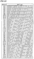
- Figure 27 illustrates a table containing values of x ⁇ (4/3) for values of x in a range of 0 ⁇ x ⁇ 8191.
- a decoding operation based on the MPEG 2 audio encoding standard AAC requires calculation of x ⁇ (4/3) for a value of x in the range from 0 to 8191.
- an input value of x is used as an address for reading out the corresponding value from a table provided in advance, as illustrated in Figure 27 , to obtain the value of x ⁇ (4/3) an output value z.
- a bit stream encoded based on the MPEG 2 audio encoding standard AAC contains a quantization code "x” and a scaling factor "y".
- the quantization code "x" and the scaling factor "y” are both integers.
- the decoding device calculates x ⁇ (a/b)*2 ⁇ (y/c) (where a, b and c are constants) for given values of x and y. Details of the MPEG 2 audio encoding standard AAC are disclosed in ISO/IEC 13818-7:1997, pp.57-59.
- Figure 28 illustrates an exemplary 32-bit fixed point format.
- bit 0 is the least significant bit and the bit 31 is the most significant bit
- the decimal point is fixed between the bit 30 and the bit 29.
- bit 30 represents the integral portion of a value
- bits 29-0 represent the fractional portion of the value.
- Bit 31 is the sign bit indicating whether the value is positive or negative.
- Such a numeric representation with a fixed decimal point is called a "fixed point format”.
- a value "f" represented in the 32-bit fixed point format, as illustrated in Figure 28 can vary in the range of -2 ⁇ f ⁇ 2. Then, in order to perform a calculation with a fixed-point-format processing unit, such as a DSP, values involved in the calculation are adjusted so that they are each in the range of ⁇ 2.0 before performing the intended calculation.
- a fixed-point-format processing unit such as a DSP
- x can vary in the range of 0 ⁇ x ⁇ 8192, whereas y can vary in the range of -100 ⁇ y ⁇ 156.
- Expression (1) may be calculated as follows based on the prior art technique with a fixed-point-format processing unit. First, Expression (1) is converted to Expression (2) below. x ⁇ (4/3)*2 ⁇ ((y%4)/4)*2 ⁇ int(y/4)
- Expression (1) or (2) assumes the use of a fixed-point-format processing unit.
- different values of x ⁇ (4/3) are normalized and stored in a table in advance, with the maximum value thereof being normalized to a value which does not exceed 1.0.
- Figure 29 illustrates the contents of a first table for use with a conventional decoding device.
- the table illustrated in Figure 29 contains values of f(x) for the range of 0 ⁇ x ⁇ 8192 at addresses which correspond to the respective values of x.
- the values of f(x) are obtained by first calculating x ⁇ (4/3) for various values of x, and then dividing the calculated values by 2 ⁇ 18 to normalize the values so that none of them exceeds 1.0.
- 2 ⁇ ((y%4)/4) is then calculated.
- 2 ⁇ ((y%4)/4) is also calculated using a ROM table.
- different values of 2 ⁇ ((y%4)/4) for various integers (y%4) are calculated and stored in a table in advance. Then, an integer (y%4) is used as an address for referencing the table so as to obtain the value of 2 ⁇ ((y%4)/4) for the integer (y%4).
- Figure 30 illustrates the contents of a second table for use with a conventional decoding device.
- the second table illustrated in Figure 30 contains values of g(y) for the address values (y%4) in the range from 0 to 3.
- the values of g(y) are obtained by normalizing values of 2 ⁇ ((y%4)/4) so that none of them exceeds 2.0.
- the value of Expression (2) can be obtained.
- the first table illustrated in Figure 29 is referenced using an input integer x as an address so as to obtain the normalized value f(x) for x ⁇ (4/3).
- (y%4) is calculated for a given integer of y.
- h(x,y) is multiplied by 2 ⁇ int(y/4) so as to obtain a multiplied value i(x,y) as a calculation result of Expression (2).
- the multiplication can be performed by a bit shift operation.
- bit shift operation it is assumed that a limit operation (so called a "clipping operation") is performed when the final calculation result exceeds the range of ⁇ 2.
- clipping operation a limit operation
- the number of significant digits of the calculated value f(x) is undesirably small for relatively small input integers of x, as those in the upper portion of Figure 29 .
- a calculation performed by using such a table results in a poor accuracy in the calculation result.
- the conventional calculation method employs a wide range of x (i.e., 0-8191), and accordingly requires a memory area as large as 8191*32 bits. Consequently, a conventional decoding device requires a table having a very large capacity.
- an exponential calculation device for calculating x ⁇ (a/b) (where a and b are each an integer constant) for a given input value of x.
- the input control section calculates the value of x' by shifting x down by b bits when x>A.
- the core section stores in a table values of x' ⁇ (a/b) for all possible values of x' (where 0 ⁇ x' ⁇ A).
- A is set to a value such that x is less than or equal to A at a frequency equal to or greater than a predetermined value.
- an exponential calculation device for calculating x ⁇ (a/b) (where a and b are each an integer constant) for a given input value of x.
- the input control section calculates the value of x' by shifting x down by (b*n) bits when x>A.
- the core section stores in a table values of x' ⁇ (a/b) for all possible values of x' (where 0 ⁇ x' ⁇ A).
- A is set to a value such that x is less than or equal to A at a frequency equal to or greater than a predetermined value.
- an exponential calculation device for calculating x ⁇ (a/b) (where a and b are each an integer constant) for a given input value of x.
- A is set to a value such that x is less than or equal to A at a frequency equal to or greater than a predetermined value.
- an exponential calculation device for calculating x ⁇ (a/b) (where a and b are each an integer constant) for a given input value of x.
- the output control section includes a memory section for storing values of 2 ⁇ (j*a/b) using j as an address; and the value of z is calculated by reading out a corresponding value of 2 ⁇ (j*a/b) from the memory section when x>A.
- an exponential calculation device for calculating x ⁇ (a/b) (where a and b are each an integer constant) for a given input value of x.
- the output control section includes a memory section for storing values of 2 ⁇ ((k-B)*a/b) using k as an address; and the value of z is calculated by reading out a corresponding value of 2 ⁇ ((k-B)*a/b) from the memory section.
- the core section includes a memory section for storing values of q ⁇ (a/b) (where 2 ⁇ (B-1) ⁇ q ⁇ 2 ⁇ B, and q is an integer) using at least lower (B-1) bits of q as an address; and the value of z' is calculated by reading out a corresponding value of q ⁇ (a/b) from the memory section using the at least lower (B-1) bits of x' as an address.
- a decoding device for extracting a variable quantization code x and a variable scaling factor y from an input bit stream containing the quantization code x and the scaling factor y and calculating x ⁇ (a/b)*2 ⁇ (y/c) (where a, b and c are each an integer constant).
- the number of bits according to N is (D-N) (where D is a number of significant digits of a fractional portion of a number involved in a fixed point calculation operation); and the number of bits according to y1 is ( y1+(N+M) ).
- M is an integer obtained by rounding up (N*(a-b))/b .
- the device further includes: a determination section for outputting a determination result being true when x ⁇ 2 ⁇ N and being false when x>2 ⁇ N; and a second division section for outputting the value of x without alteration when the determination result is true and for outputting a value obtained by dividing x by (2 ⁇ (b*i)).
- the first bit shift section shifts x by a number of bits according to ( N+b*i ) (where i is an integer which is not negative) when the determination result is false.
- the first memory section stores values of H(q) for values of q which are within the variable range of x.
- the second bit shift section shifts the value output from the multiplication section by a number of bits according to y1 when the determination result is true and by a number of bits according to y1 and a*i when the determination result is false.
- the number of bits according to N is (D-N); the number of bits according to ( N+b*i ) is D-(N+b*i) ; the number of bits according to according to M is (D-M); the number of bits according to according to y1 is ( y1+N+M ); and the number of bits according to y1 and a*i is ( y1+N+M+a*i ).
- the value of i is determined so that x satisfies 2 ⁇ (N+b(i-1)) ⁇ x ⁇ 2 ⁇ (N+bi) .
- the device further includes a determination section for outputting a determination result being true when x ⁇ 2 ⁇ N and being false when x>2 ⁇ N, and further outputting a parameter i for specifying a value of x.
- the first bit shift section and the second division section and the second shifting section operate according to the determination result from the determination section.
- the second bit shift section shifts the value output from the multiplication section by a number of bits according to y1 when the determination result is true and by a number of bits according to y1+(a*i) when the determination result is false.
- a decoding device for extracting a variable quantization code x and a variable scaling factor y from an input bit stream containing the quantization code x and the scaling factor y and calculating x ⁇ (a/b)*2 ⁇ (y/c) (where a, b and c are each an integer constant).
- the adjustment coefficient generation section includes a second memory section for storing values of I(p,j) using p and j as an address.
- a decoding device for extracting a variable quantization code x and a variable scaling factor y from an input bit stream containing the quantization code x and the scaling factor y and calculating x ⁇ (a/b)*2 ⁇ (y/c) (where a, b and c are each an integer constant).
- the adjustment coefficient generation section includes a second memory section for storing values of I(p,k) using p and k as an address.
- the invention described herein makes possible the advantages of: (1) reducing the hardware scale of an exponential calculation device which is capable of calculating x ⁇ (a/b) for a given value of x, by reducing the memory area to be used for a table; (2) realizing a decoding device capable of calculating x ⁇ (a/b)*2 ⁇ (y/c) with a high accuracy using a fixed-point-format processing unit even when the integer x is considerably smaller than the maximum value of the variable range thereof; (3) realizing a decoding device which only has a table for relatively small integers x and still is capable of calculating x ⁇ (a/b)*2 ⁇ (y/c) even for a large value of x by using the small-capacity table; and (4) realizing a calculation method capable of a calculation involving a large value of x using a small-capacity table by the use of a simple bit shift operation, thereby realizing a decoding device capable of rapidly calculating x ⁇ (a/b)*2 ⁇ (
- An exponential calculation device of the present invention only requires a table containing values of x ⁇ (a/b) for input values of x less than or equal to a predetermined value A, and still is capable of obtaining a value of x ⁇ (a/b) for any input value of x.
- the present invention does not require a large table for storing values of x ⁇ (a/b) for input values of x greater than A, and accordingly requires a memory area much smaller than that of the conventional exponential calculation device which requires a large table for storing values of x ⁇ (a/b) for all the possible input values of x.
- x is first divided by a predetermined value to obtain x' such that x' ⁇ A.
- a value x' ⁇ (a/b) is read out from the table and is multiplied by the predetermined value so as to obtain the value of x ⁇ (a/b) for the given value of x.
- a value of x ⁇ (a/b) for any given value of x can be obtained.
- x' x/8 .
- the exponential calculation device of this example performs an exponential calculation x ⁇ (4/3).
- the range of the input value of x is 0-8191.
- the range of the exponentiated value x ⁇ (4/3) and the range of the input value of x conform to the MPEG 2 audio AAC standard (see ISO/IEC 13818-7:1997, P57).
- Figure 1 is a block diagram illustrating a structure of an exponential calculation device 100 according to Example 1 of the present invention.
- the exponential calculation device 100 includes an input control section 10 , a core section 11 and an output control section 12 .
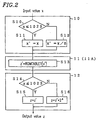
- FIG. 2 is a flow chart illustrating signal processing performed by the exponential calculation device 100 , showing respective signal processing steps performed by the input control section 10 , the core section 11 and the output control section 12. Referring to Figure 2 , the respective components of the exponential calculation device 100 will now be described in detail.
- the input control section 10 determines if the input value of x is less than or equal to a threshold value A (e.g., 1023 in this example). If the input value of x is less than or equal to 1023, the input control section 10 provides the value of x, without alteration, as x' to the core section 11 . If the input value of x exceeds 1023, the input control section 10 provides a value obtained by dividing x by 2 ⁇ 3 as x' to the core section 11.
- a threshold value A e.g. 1023 in this example.
- the core section 11 provides the value of x' ⁇ (4/3) for the value of x', which is in the range from 0 to 1023.
- the core section 11 illustrated in Figure 2 is one example of the core section 11 and will hereinbelow be referred to as the "core section 11A ".
- the core section 11A outputs a value read out from the ROM Table 1 for the value of x' as z'.
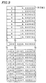
- Figure 3 illustrates the contents of the ROM Table 1 of the core section 11A .
- the ROM Table 1 contains values of x' ⁇ (4/3) which have been calculated for value of x' in the range from 0 to 1023.
- the output control section 12 provides the output value z' from the core section 11A , without alteration, as z when the input value of x is less than or equal to 1023, and provides a value obtained by multiplying the output value from core section 11A by 2 ⁇ 4 as z when x exceeds 1023.
- step S10 determines if a given value of x is less than or equal to 1023. When x does not exceed 1023, the process proceeds to step S11 , thereby providing the value of x, without alteration, as x' to the core section 11A . If it is determined that x exceeds 1023, the process proceeds to step S12 so as to provide x' by dividing x by 2 ⁇ 3 to the core section 11A .
- the division of x by 2 ⁇ 3 can be performed, for example, by shifting x down by 3 bits or by first adding 4 to x and then shifting down the obtained value by 3 bits for a "0-down-1-up" round-off process, where .0's are rounded down and .1's are rounded up.
- step S13 the core section 11A reads out from the ROM Table 1 , as illustrated in Figure 3 , a value of x' ⁇ (4/3) for the value of x' provided by the input control section 10 .
- Figure 4 is a flow chart illustrating a signal processing procedure performed by another exemplary core section 11B for use with the exponential calculation device 100 .
- the core sections 11A and 11B as illustrated in Figures 2 and 4 , respectively, may be used interchangeably in the present invention.
- the core section 11B raises z' (from the ROM Table 2 ) to the power of m, and outputs the resulting value as new z'.
- Figure 5 illustrates the contents of the ROM Table 2 of the core section 11B .
- z' is read out from the ROM Table 2 and, in step S18 , z' is raised to the power of 4 , thereby obtaining the value of x'(4/3).
- Such an additional exponential calculation as is required in this core section 11B can easily be processed by a multiplier of a DSP, thereby maintaining a small capacity of the ROM table.
- step S14 the output control section 12 determines if the input value of x is less than or equal to 1023. When x is less than or equal to 1023, the process proceeds to step S15 , thereby outputting the output value from the core section 11 , without alteration. When it is determined that the input value of x exceeds 1023 in step S14 , the process proceeds to step S16 , thereby outputting a value obtained by multiplying the output value from the core section 11 by 2 ⁇ 4.
- 1023 is selected as the threshold value A for the following reasons.
- the input value of x ⁇ (4/3) can range from 0 to 8191. In fact, however, values from 0 to 1023 are involved in most cases. Therefore, for x ranging from 0 to 1023, the calculation x ⁇ (4/3) should accurately be performed so as not to deteriorate the sound quality.
- the sound quality would not significantly deteriorate even if the calculation is not as accurate as that for x ranging from 0 to 1023. Accordingly, for x exceeding 1023, an approximate calculation can be performed according to the method of the present example.
- the statistic threshold value A may be set to 255.
- the following example of the invention will discuss an example where the statistic threshold value is set to 255.
- Example 2 of the present invention provides an exponential calculation device for obtaining a value of x ⁇ (4/3), as an exemplary exponentiated value x ⁇ (a/b).
- the exponential calculation device of the present example can be characterized in that it performs the exponential calculation x ⁇ (a/b) by performing two exponential calculations for an integral portion of a/b and for a fractional portion thereof (where a and b are each an integer, and a>b).
- the exponential calculation for the integral portion of a/b can therefore be expressed as x ⁇ (int(a/b)), whereas the exponential calculation for the fractional portion of a/b can be expressed as x ⁇ ((a%b)/b).
- int() denotes a round-down operation, where any fractional portion of the number is cut off
- % denotes a modulo operation for obtaining a remainder (integer) of a division
- the range of input values of x is from 0 to 8191, conforming to the MPEG 2 audio AAC standard (see ISO/IEC 13818-7:1997, P57).
- FIG. 6 is a block diagram illustrating a structure of an exponential calculation device 200 according to Example 2 of the present invention.
- the exponential calculation device 200 includes an input control section 20 , a core section 21 , an output control section 22 and a multiplication section 23 .
- Figure 7 is a flow chart illustrating a signal processing method of the exponential calculation device 200 , showing the respective signal processing procedures performed by the input control section 20 , the core section 21 , the output control section 22 and the multiplication section 23 .
- the input control section 20 When the input value of x is less than or equal to 255 (first threshold value A1), the input control section 20 provides the value of x, without alteration, to the core section 21 as x'. When the input value of x exceeds 255 but is less than or equal to 2047 (second threshold value A2), the input control section 20 provides a value obtained by dividing x by 2 ⁇ 3 to the core section 21 as x'. When the input value of x is equal to or grater than 2048, the input control section 20 provides a value obtained by dividing x by 2 ⁇ 6 to the core section 21 as x'.
- Figure 8 illustrates the contents of a ROM Table 3 of the exponential calculation device 200 .
- the core section 21 has the ROM Table 3 , as illustrated in Figure 8 , and provides values of x' ⁇ ((a%b)/b) (i.e., x' ⁇ (1/3)) for values of x' from 0 to 255.
- the values of x' ⁇ (1/3) for values of x' from 0 to 255 are stored in the ROM Table 3 in advance.
- the output control section 22 When the input value of x is less than or equal to the first threshold value A1, the output control section 22 outputs the output value from the core section 21 , without alteration. When the input value of x exceeds the first threshold value A1 but less than or equal to the second threshold value A2, the output control section 22 outputs a value obtained by multiplying the output value z' from the core section 21 by 2 ⁇ (a%b) as z. When the input value of x exceeds the second threshold value A2, the output control section 22 outputs a value obtained by multiplying the output value from the core section 21 by 2 ⁇ ((a%b)*2). The multiplication section 23 multiplies x ⁇ (int(a/b)) with the output value z from the output control section 22 so as to output the multiplied value as a new value of z.
- step S20 the input control section 20 determines if the input value of x is less than or equal to the first threshold value, 255. When the input value of x is less than or equal to 255, the process proceeds to step S21 , thereby providing the value x, without alteration, to the core section 21 as x'. If it is determined in step S20 that the input value of x is equal to or greater than 256, the process proceeds to step S22 , where it is determined if the input value of x is less than or equal to the second threshold value A2, 2047.
- step S23 When x is less than or equal to 2047, the process proceeds to step S23 , where a value obtained by dividing x by 2 ⁇ 3 is provided to the core section 21 as x'.
- step S24 When it is determined in step S22 that the input value of x is equal to or greater than 2048, the process proceeds to step S24 , where a value obtained by dividing x by 2 ⁇ 6 is provided to the core section 21 as x'.
- the division of x by 2 ⁇ 3 can be performed, for example, by shifting x down by 3 bits or by first adding 4 to x and then shifting down the obtained value by 3 bits for the "0-down-1-up" round-off process.
- the division of x by 2 ⁇ 6 can be performed, for example, by shifting x down by 6 bits or by first adding 32 to x and then shifting down the obtained value by 6 bits for the "0-down-1-up" round-off process.
- step S25 the core section 21 reads out a value of x' ⁇ (1/3) from the ROM Table 3 , as illustrated in Figure 8 , for a value of x' provided by the input control section 20 .
- step S26 the output control section 22 determines if the input value of x is less than or equal to 255. If x is less than or equal to 255, the process proceeds to step S27 , thereby outputting the output value from the core section 21 , without alteration.
- step S28 determines if the input value of x is less than or equal to 2047. If x is less than or equal to 2047, the process proceeds to step S29. If x is equal to or greater than 2048, the process proceeds to step S30 .
- Step S29 outputs a value obtained by multiplying the output value from the core section 21 by 2 ⁇ 1
- Step S30 outputs a value obtained by multiplying the output value from the core section 21 by 2 ⁇ 2.
- step S31 the multiplication section 23 multiplies the input value of x with the output value from the output control section 22 .
- the value to be obtained is x ⁇ (4/3)
- the output value from the output control section 22 is x ⁇ (1/3). Therefore, x ⁇ (4/3) is calculated by multiplying the original value of x with x ⁇ (1/3).
- an exponential calculation device for calculating x ⁇ (a/b) (where a>b) for an input value of x includes a core section for providing values of x' ⁇ ((a%b)/b) for values of x' from 0 to A.
- the exponential calculation device of the present invention is provided with a multiplication section for multiplying a value of x ⁇ (int(a/b)), for an input value of x, with an output value from the output control section.
- This example provides an exponential calculation device for obtaining a value of x ⁇ (1/3), as an exemplary exponentiated value x ⁇ (a/b).
- the input value of x is assumed to range from 0 to 8191.
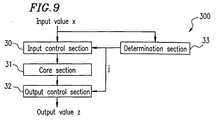
- Figure 9 is a block diagram illustrating a structure of an exponential calculation device 300 according to Example 3 of the present invention.
- the exponential calculation device 300 includes an input control section 30 , a core section 31, an output control section 32 and a determination section 33 .
- Figure 10 is a flow chart illustrating a signal processing method of the exponential calculation device 300 , showing the respective signal processing procedures performed by the input control section 30 , the core section 31 , the output control section 32 and the determination section 33 .
- the input control section 30 determines if the input value of x is less than or equal to the threshold value A (e.g., 1023 in this example). If x is less than or equal to 1023, the input control section 30 provides the value of x, without alteration, to the core section 31 as x'. If x is greater than 1023, the input control section 30 provides a value obtained by dividing x by 2 ⁇ j to the core section 31 as x'.
- the threshold value A e.g. 1023 in this example
- the value of j is determined by the determination section 33 as follows.
- the value "10" is the number of digits of a value 1024 represented in the binary form. Accordingly, the value of j represents by how many digits x is greater than the threshold value A in the binary form.
- the core section 31 includes a ROM Table 2 , as illustrated in Figure 5 . Values of x' ⁇ (1/3) for x' from 0 to 1023 have been calculated and stored in the ROM Table 2 .
- the core section 31 provides values of x' ⁇ (1/3) for x' from 0 to 1023.
- the output control section 32 When the input value of x is less than or equal to 1023, the output control section 32 outputs the value of z' from the core section 31 , without alteration, as z.
- the output control section 32 outputs a value obtained by multiplying the value of z' output from the core section 31 by 2 ⁇ (j/3), as z.
- the input control section 30 of Figure 10 first receives an input value of x and determines, in step S40 , if the value of x is less than or equal to 1023. When x is less than or equal to 1023, the process proceeds to step S41 , whereby the value of x is provided, without alteration, to the core section 31 as x'. When it is determined in step S40 , that the input value of x is greater than 1023, the process proceeds to step S42 , a value obtained by dividing x by 2 ⁇ j is provided to the core section 31 as x'.
- the division of x by 2 ⁇ j can be performed, for example, by shifting x down by j bits or by first adding 2 ⁇ (j-1) to x and then shifting down the obtained value by j bits for the "0-down-1-up" round-off process.
- step S43 the core section 31 reads out the value of x' ⁇ (1/3) from the ROM Table 2 in Figure 5 for the value of x' provided from the input control section 30 .
- step S44 the output control section 32 determines if the input value of x is less than or equal to 1023. When x is less than or equal to 1023, the process proceeds to step S45 , whereby the output value from the core section 31 is output, without alteration. When it is determined in step S44 that the input value of x is greater than 1023, the process proceeds to step S46 , thereby outputting a value obtained by multiplying the output value from the core section 31 by 2 ⁇ (j/3).
- Figure 11 illustrates a table for providing a value of 2 ⁇ (j/3) in an output control section 32 of the exponential calculation device 300 .
- Values of 2 ⁇ (j/3) can be stored in advance in a table using j as an address, so that a value of 2 ⁇ (j/3) for a given value of j can be obtained by reading out the value from the table.
- the multiplication of the output value from the core section 31 by 2 ⁇ (j/3) can be performed using an ordinary multiplier.
- the threshold value A is set to 1023, the highest possible value represented by 10 bits, and the determination section 33 is constructed so as to output a value which indicates by how many bits the number of bits of x is greater than 10 bits.
- the present invention is not limited to such a structure.
- the threshold value A can be set to 255, the highest possible value represented by 8 bits, and the determination section 33 can be constructed accordingly so as to output a value which indicates by how many bits the number of bits of x is greater than 8 bits.
- the threshold value A can be set to 4095, the highest possible value represented by 12 bits, and the determination section 33 can be constructed accordingly so as to output a value which indicates by how many bits the number of bits of x is greater than 12 bits.
- This example provides an exponential calculation device for obtaining a value of x ⁇ (1/3), as an exemplary exponentiated value x ⁇ (a/b).
- the input value of x is assumed to range from 0 to 8191.
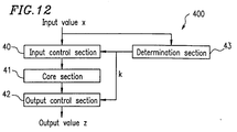
- FIG 12 is a block diagram illustrating a structure of an exponential calculation device 400 according to Example 4 of the present invention.
- the exponential calculation device 400 includes an input control section 40 , a core section 41 , an output control section 42 and a determination section 43 .
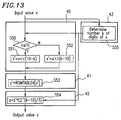
- Figure 13 is a flow chart illustrating a signal processing method of the exponential calculation device 400 , showing the respective signal processing procedures performed by the input control section 40 , the core section 41 , the output control section 42 and the determination section 43 .
- the determination section 43 determines the number k of digits of x represented in the binary form.
- the input control section 40 determines if k is less than or equal to a threshold value B (e.g., 10 in this example). When x is less than or equal to 10, the input control section 40 provides to the core section 41 a value obtained by shifting x up by (B-k) bits as x'. When x is greater than 10, the input control section 40 provides to the core section 41 a value obtained by shifting x down by (k-B) bits as x'.
- B e.g. 10 in this example
- the output control section 42 outputs a value obtained by multiplying z' output from the core section 41 by 2 ⁇ ((k-B)/3) .
- Figure 14 illustrates the contents of a ROM Table 4 of a core section 41 of the exponential calculation device 400 . Values of x' ⁇ (1/3) for values of x' from 512 to 1023 are stored in the ROM Table 4 in advance.
- the table contains such values for the following reason.
- k denotes the number of bits of x represented in the binary form
- the input control section 40 calculates x' by shifting x up by (B-k) bits when B-k is positive and by shifting x down by (k-B) bits when B-k is negative, whereby the B th bit of x' is always 1.
- the value is always in the range from 2 ⁇ (B-1) to 2 ⁇ B-1. Therefore, the table of Figure 14 can be referenced using only the lower (B-1) bits of x' as an address. As a result, the size of the table can be reduced to half.
- the determination section 43 of Figure 12 first determines the number k of digits of x represented in the binary form in step S55 .
- step S53 the core section 41 reads out from the ROM Table 4 of Figure 14 a value of x' ⁇ (1/3) for the value of x' provided from the input control section 40 .
- step S54 the output control section 42 of Figure 12 outputs a value obtained by multiplying the output value from the core section 41 by 2 ⁇ ((k-B)/3) .
- Figure 15 illustrates a table for providing a value of 2 ⁇ ((k-B)/3) in an output control section 42 of the exponential calculation device 400 .
- Values of 2 ⁇ ((k-B)/3) can be stored in advance in a table using k as an address, so that a value of 2 ⁇ ((k-B)/3) for a given value of k can be obtained by reading out the value from the table.
- the multiplication of the output value from the core section 41 by 2 ⁇ ((k-B)/3) can be performed using an ordinary multiplier.
- the present example does not require providing values of x ⁇ (1/3) for all the possible values of x contemplated (e.g., 0-8191 in this example), but only requires providing values of x' ⁇ (1/3) for input values of x less than or equal to the predetermined threshold value B (e.g., 10 in this example). In this way, values of x ⁇ (1/3) for input values of x which has more than B bits can also be approximately calculated. Thus, it is possible to perform an exponential calculation with small-scale hardware.
- the present example provides an advantage that the size of the table can be reduced to half while maintaining substantially the same level of accuracy as that in Example 3 in calculating x ⁇ (1/3) for x having more than B bits.
- a decoding device according to Example 5 of the present invention will now be described with reference to the figures.
- a bit stream encoded based on the MPEG 2 audio encoding standard AAC contains a quantization code "x" and a scaling factor "y".
- a decoding device of the present example is an encoding device for calculating x ⁇ (a/b)*2 ⁇ (y/c) for values of x and y contained in the audio bit stream.
- the quantization code x is any integer in the range from 0 to 8191, for example, and the scaling factor y is any integer from -100 to 156.
- These variable ranges of x and y conform to the MPEG 2 audio encoding standard AAC (see ISO/IEC 13818-7:1997). In the following description, it is assumed that x and y take these variable ranges, though the present invention is not limited thereto.
- FIG 16 is a block diagram illustrating a structure of a decoding device 500 according to Example 5 of the present invention.
- the decoding device 500 includes an isolation section 50, a determination section 51 , a first memory section 52 , a second memory section 53 , a division section 54 , a modulo calculation section 55 , a multiplication section 56 and a bit shift section 57 .
- the isolation section 50 isolates the quantization code x and the scaling factor y from an input bit stream.
- the determination section 51 determines if the quantization code x output from the isolation section 50 is less than or equal to 2 ⁇ N (where N is a predetermined integer threshold value).
- the determination section 51 outputs a determination result being true when x ⁇ 2 ⁇ N and being false when x>2 ⁇ N.
- the first memory section 52 stores values according to q ⁇ (a/b) in the fixed point format for integer values of q ranging from 0 to (2 ⁇ Q-1) (wherein Q is an integer).
- the first memory section 52 has the following structure. Where q is any integer within the variable range of x which is isolated from the bit stream by the isolation section 50 (0 ⁇ q ⁇ 2 ⁇ Q-1), the first memory section 52 stores values of q ⁇ (a/b) for all the possible values of q in the fixed point format. Thus, the first memory section 52 stores values of F(q) using q as an address. When the integer value q exceeds 2 ⁇ N (N is a predetermined threshold value), F(q) represents values obtained by normalizing values of q ⁇ (a/b) with 2 ⁇ M'.
- F(q) represents values obtained by normalizing values of q ⁇ (a/b) with 2 ⁇ M' and then shifting the resulting value by (M'-M) bits.
- M is an integer value of (N*a)/b
- M' is an integer value of (Q*a) divided by b.
- the integer M is a value obtained by rounding up the value of (N*a)/b
- the integer M' is a value obtained by rounding up (Q*a)/b .
- Figure 17 illustrates the contents of the first memory section 52 of the decoding device 500 .
- the most significant bit is a sign bit and a decimal point is between the second bit and the third bit from the most significant bit.
- the second bit next to the most significant bit and D bits on the right of the decimal point are significant digits to be calculated.
- the fixed point format of the values G(p) in Figure 18 may be the same as that in Figure 28 .
- the multiplication section 56 multiplies a value of F(x) read out from the first memory section 52 by a value of G(y2) read out from the second memory section 53 .
- the bit shift section 57 shifts the output value from the multiplication section 56 by ( y1-(M'-M) ) bits, if the determination result from the determination section 51 is true, and by y1 bits, if the determination result from the determination section 51 is false, thereby outputting the shifted value.
- the isolation section 50 of Figure 16 isolates the quantization code x and the scaling factor y from an input bit stream. Then, the determination section 51 determines if the quantization code x is less than or equal to 2 ⁇ 5.
- the division section 54 obtains the quotient y1 of the division of the scaling factor y by 4, and the modulo calculation section 55 obtains the remainder y2 of the division of the scaling factor y by 4.
- the multiplication section 56 multiplies the value of F(x) from address x of the first memory section 52 by the value of G(y2) from the address y2 of the second memory section 53 .
- the decoding device of this example receives a bit stream encoded based on the MPEG 2 audio decoding standard, isolates the quantization code x and the scaling factor y contained therein, and calculates Expression (3) below which is a generalized form of Expression (1).
- variable range of the quantization code x is from 0 to 4096
- variable range of the scaling factor y is from -100 to 156, for example.
- Expression (3) is converted to Expression (4) below. x*x ⁇ ((a-b)/b)*2 ⁇ ((y%c)/c)*2 ⁇ int(y/c)
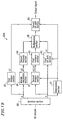
- FIG 19 is a block diagram illustrating a structure of a decoding device 600 according to Example 6 of the present invention.
- the decoding device 600 includes an isolation section 60, a determination section 61 , a first bit shift section 62 , a first memory section 63 , a second memory section 64 , a first division section 65 , a modulo calculation section 66 , a second division section 67 , a multiplication section 68 and a second bit shift section 69 .
- the isolation section 60 isolates the quantization code x and the scaling factor y from the input bit stream.
- the determination section 61 determines if the quantization code x is less than or equal to 2 ⁇ N (where N is a threshold value corresponding to the number of addresses of the first memory section 63 ), thereby outputting a determination result being true, if x ⁇ 2 ⁇ N, and being false, if x>2 ⁇ N.
- the determination section 61 further outputs a parameter i for specifying a value of the variable x (where i is an integer which is not negative; and the variable range of x is from 2 ⁇ N to 2 ⁇ (N+b*i) ).
- the value of i is determined so that x satisfies 2 ⁇ (N+3(i-1) ⁇ x ⁇ 2 ⁇ (N+3i) .
- the determination result from the determination section 61 and the value of the parameter i are provided to the second division section 67 , the first bit shift section 62 and the second bit shift section 69 .
- the multiplication section 68 functions to perform a calculation for an input value having a bit width of (D+2) in the fixed point format, where the most significant bit of the input value indicates whether the value is positive or negative, and the second most significant bit and the D bits to the right of the decimal point represent the significant digits of the input value.
- the first bit shift section 62 converts the integer x to x1 which is a value having the fixed point format by shifting x by D-N bits, if the determination result from the determination section 61 is true, and by D-(N+b*i) bits (utilizing the value of i), if the determination result from the determination section 61 is false.
- the first division section 65 performs a division of the value of y output from the isolation section 60 by c so as to output the quotient y1 thereof.
- the modulo calculation section 66 performs a division of the value of y output from the isolation section 60 by c so as to output the remainder y2 thereof.
- the second division section 67 receives the value of x which has been isolated by the isolation section 60 , so as to output the value of x, without alteration, as x2, if the determination result from the determination section 61 is true, and to output an integer value of x/(2 ⁇ (b*i)) as x3, if the determination result from the determination section 61 is false.
- the first memory section 63 stores values of H(q) for values of q (q is an integer value in the range from 0 to 2 ⁇ N).
- the values of H(q) are obtained by converting values of q ⁇ ((a-b)/b ) into the fixed point format by shifting the values of q ⁇ ((a-b)/b) by (D-M) bits (where M is an integer value of N*(a-b) divided by b).
- the contents of the second memory section 64 may be the same as that shown in Figure 18 , that is, values of 2 ⁇ (p/c) for integer values of p in the range from 0 to 3.
- the multiplication section 68 multiplies together a value from address x2 or x3 of the first memory section 63 , a value from address y2 of the second memory section 64 and a value of x1 output from the first bit shift section 62 .
- M is an integer value of N*(a-b) divided by b
- the second bit shift section 69 shifts the output value from the multiplication section 68 by ( y1+N+M ) bits, if the determination result from the determination section 61 is true, and by ( y1+N+M+a*i ) bits, if the determination result from the determination section 61 is false.
- Figure 20 illustrates the contents of the first memory section 63 of the decoding device 600 .
- the table illustrated in Figure 20 contains values of H(q) in the fixed point format which are obtained by normalizing values of q ⁇ ((a-b)/b) with 2 ⁇ M (where q is an integer value in the range from 0 to 2 ⁇ N).
- the most significant bit is a sign bit
- a decimal point is between the second bit and the third bit from the most significant bit.
- a value of H(q) is at least -2 and at most less than 2.
- Figure 21 illustrates a method of converting an integer value to value of a fixed point format.
- N may alternatively be set to 10
- M is set to an integer value, 4, which is obtained by rounding up 10*(4-3)/3.
- the isolation section 60 of Figure 19 isolates the quantization code x and the scaling factor y from the input bit stream.
- the determination section 61 further outputs a value of i according to the variable range of the quantization code x.
- the first bit shift section 62 converts the integer value of x to x1 having the fixed point format by shifting x by (30-9) bits, if the determination result from the determination section 61 is true, and by 30-(9+3) bits, if the determination result from the determination section 61 is false.
- the most significant bit is a sign bit
- a decimal point is between the second bit and the third bit from the most significant bit.
- x is a value which has 9 bits or less (i.e., less than or equal to 2 ⁇ 9)
- the second division section 67 outputs the value of x, without alteration, as x2, when the determination result from the determination section 61 is true, and outputs an integer value of x/8 as x3, when the determination result from the determination section 61 is false, i.e., when x is greater than 2 ⁇ 9 and less than or equal to 2 ⁇ 12.
- the value of x3 is used as an address of the first memory section 63 because the first memory section 63 only stores values according to q ⁇ (1/3) for integer values of q from 0 to 2 ⁇ 9, i.e., 512.
- the first division section 65 obtains a quotient y1 of a division of y by 4, and the modulo calculation section 66 obtains a remainder y2 of the division of y by 4. Then, the multiplication section 68 multiplies together a value of H(x2) from address x2 of the first memory section 63 , a value of G(y2) from address y2 of the second memory section 64 and a value x1 output from the first bit shift section 62 .
- the multiplication section 68 provides a value corresponding to x*x ⁇ (1/3)*2 ⁇ ((y%4)/4) according to Expression (4) which is converted from Expression (3) (a value before the number of digits, i.e., gain, thereof is adjusted).
- Expression (4) which is converted from Expression (3) (a value before the number of digits, i.e., gain, thereof is adjusted).
- the output x1 from the first bit shift section 62 represents a value of x as converted into the fixed point format
- the first memory section 63 stores values corresponding to x ⁇ (1/3) in the fixed point format
- the second memory section 64 stores values according to 2 ⁇ (q/4) for integer values of p in the range from 0 to 3 in the fixed point format.
- the effect of this operation is as follows. First, the operation of shifting the output value by y1 bits is a calculation corresponding to the fourth term of Expression (4), i.e., 2 ⁇ int(y/4).
- the value y1 is a quotient of the division of y by 4 obtained by the first division section 65 .
- the output value from the multiplication section 68 is multiplied by 2 ⁇ (y1+9+3), i.e., shifted up by (y1+9+3) bits, so as to convert the output value to a value as represented in the original integer format.
- the value of x is normalized with 2 ⁇ (9/3) by the first bit shift section 62 so as to be converted to a value which does not exceed 1.0.
- the respective values stored in the first memory section 63 which are originally less than or equal to 2 ⁇ (9/3), are also normalized with 2 ⁇ 3 so as to be converted to values which do not exceed 1.0.
- This bit shift operation converts the output value from the multiplication section 68 to a value in the original integer representation.
- the quantization code x is assumed to range from 0 to 4095, whereas it ranges from 0 to 8191 according to the MPEG 2 AAC standard.
- a method of performing a calculation in the case where the quantization code x is 4096 or greater, while assuming i 2. It should be noted herein that 4096 is 2 ⁇ (9+3).
- the second division section 67 obtains x2 which is an integer value of x/(2 ⁇ (3*2)) for the given value of x.
- the multiplication section 68 multiplies together a value from address x2 of the first memory section 63, a value from address y2 of the second memory section 64 and x1.
- the effect of the operation by the second bit shift section 69 of shifting the output value of the multiplication section 68 by ( y1+N+M+ 8) bits when x is equal to or greater than 2 ⁇ (N+3) is as follows.
- the operation of shifting by y1 bits corresponds to the calculation of 2 ⁇ int(y/4), i.e., the fourth term of Expression (4). This is because y1 is an output from the division section 65 , and the value thereof is a quotient of the division of y by 4.
- the multiplication of the output value from the multiplication section 68 by 2 ⁇ (N+M+6+2) is equivalent to shifting up the output value from multiplication section 68 by ( N+M+6+2 ) bits.
- This bit shift operation converts the output value from the multiplication section 68 to a value in the original integer representation.
- the second bit shift section 69 shifts the output value from the multiplication section 68 by ( y1+N+M+8 )bits, when x is greater than 2 ⁇ (N+3). It should be understood that since the magnitude correlation among these values in such a numerical representation is relative, the operation to be performed by the second bit shift section 69 is for, when x is greater than 2 ⁇ (N+3), adjusting the output of the multiplication section 68 so as to be greater than that when x is less than 2 ⁇ N by 8 bits.
- the decoding device of this example also receives a bit stream encoded based on the MPEG 2 audio decoding standard, isolates the quantization code x and the scaling factor y contained therein, and calculates Expression (3) below which is a generalized form of Expression (1).
- variable range of the quantization code x is from 0 to 8191
- variable range of the scaling factor y is from -100 to 156, for example.
- Expression (3) is converted to Expression (4) below. x*x ⁇ ((a-b)/b)*2 ⁇ ((y%c)/c)*2 ⁇ int(y/c)
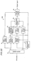
- FIG 22 is a block diagram illustrating a structure of a decoding device 700 according to Example 6 of the present invention.
- the decoding device 700 includes an isolation section 70 , a determination section 71 , a first bit shift section 72 , a first memory section 73 , an adjustment coefficient generation section 74 , a first division section 75 , a modulo calculation section 76 , a second division section 77 , a multiplication section 78 and a second bit shift section 79 .
- the isolation section 70 isolates the quantization code x and the scaling factor y from the input bit stream.
- the determination section 71 determines if the quantization code x is less than or equal to 2 ⁇ N (where N is a threshold value corresponding to the number of addresses of the first memory section 73 ), thereby outputting a determination result being true, if x ⁇ 2 ⁇ N, and being false, if x>2 ⁇ N.
- the determination section 71 further outputs a parameter j for specifying a value of the variable x (where j is an integer which is not negative; and the variable range of x is from 2 ⁇ N to 2 ⁇ (N+j)).
- the value of j is determined so that x satisfies 2 ⁇ (N+(j-1) ⁇ x ⁇ 2 ⁇ (N+j) when x is greater than 2 ⁇ N, while j is set to 0 when x is less than or equal to 2 ⁇ N.
- the determination result from the determination section 71 and the value of the parameter j are provided to the second division section 77 , the first bit shift section 72 , the second bit shift section 79 and the adjustment coefficient generation section 74 .
- the multiplication section 78 functions to perform a calculation for an input value having a bit width of (D+2) in the fixed point format, where the most significant bit of the input value indicates whether the value is positive or negative, and the second most significant bit and the D bits to the right of the decimal point represent the significant digits of the input value.
- the first bit shift section 72 converts the integer x to x1 which is a value having the fixed point format by shifting x by D-N bits, if the determination result from the determination section 71 is true, and by D-(N+j) bits (utilizing the value of j), if the determination result from the determination section 71 is false.
- the first division section 75 performs a division of the value of y output from the isolation section 70 by c so as to output the quotient y1 thereof.
- the modulo calculation section 76 performs a division of the value of y output from the isolation section 70 by c so as to output the remainder y2 thereof.
- the second division section 77 receives the value of x which has been isolated by the isolation section 70 , so as to output the value of x, without alteration, as x2, if the determination result from the determination section 71 is true, and to output an integer value of x/(2 ⁇ j) as x3, if the determination result from the determination section 71 is false.
- the first memory section 73 stores values of H(q) for values of q (q is an integer value in the range from 0 to 2 ⁇ N).
- the values of H(q) are obtained by converting values of q ⁇ ((a-b)/b) into the fixed point format by shifting the values of q ⁇ ((a-b)/b) by (D-M) bits (where M is an integer value of N*(a-b) divided by b).
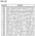
- the adjustment coefficient generation section 74 has a memory section where values of I(p,j) have been stored in advance.
- Figure 23 illustrates the contents of the adjustment coefficient generation section 74 of the decoding device 700.
- the present example also employs the fixed point format, as illustrated in Figure 28, the table for I(p,j) stores values obtained by shifting down values of 2 ⁇ (p/4)*2 ⁇ (j/3) by 2 bits.
- the adjustment for the bit shift operation by 2 bits should be accounted for in an output signal. This will be described later.
- the multiplication section 78 multiplies together a value from address x2 or x3 of the first memory section 73 , a value from address y2, j of the adjustment coefficient generation section 74 and a value of x1 output from the first bit shift section 72.
- M is an integer value of N*(a-b) divided by b
- the second bit shift section 79 shifts the output value from the multiplication section 78 by ( y1+N+M ) bits, if the determination result from the determination section 71 is true, and by ( y1+N+M+j ) bits, if the determination result from the determination section 71 is false.
- the above-described adjustment for the 2 bits due to the structure illustrated in Figure 23 is performed, i.e., the already shifted value is further shifted up by 2 bits.
- the first memory section 73 has a table containing values, as illustrated in Figure 20 .
- the table illustrated in Figure 20 contains values of H(q) in the fixed point format which are obtained by normalizing values of q ⁇ ((a-b)/b) with 2 ⁇ M (where q is an integer value in the range from 0 to 2 ⁇ N).
- the most significant bit is a sign bit, and a decimal point is between the second bit and the third bit from the most significant bit.
- a value of H(q) is at least -2 and at most less than 2.
- Figure 21 illustrates a method of converting an integer value to value of a fixed point format.
- N may alternatively be set to 10
- M is set to an integer value, 4, which is obtained by rounding up 10*(4-3)/3.
- the first bit shift section 72 converts the integer value of x to x1 having the fixed point format by shifting x by (30-9) bits, if the determination result from the determination section 71 is true, and by 30-(9+j) bits, if the determination result from the determination section 71 is false.
- the most significant bit is a sign bit
- a decimal point is between the second bit and the third bit from the most significant bit.
- x is a value which has 9 bits or less (i.e., less than or equal to 2 ⁇ 9)
- the first bit shift section 72 converts the integer value of x to x1 having the fixed point format by shifting x by a number of bits according to the number of bits of x.
- the second division section 77 outputs the value of x, without alteration, as x2, when the determination result from the determination section 71 is true, and outputs an integer value of x/(2 ⁇ j) as x3, when the determination result from the determination section 71 is false, i.e., when x is greater than 2 ⁇ 9.
- the value of x3 is used as an address of the first memory section 73 because the first memory section 73 only stores values according to q ⁇ (1/3) for integer values of q from 0 to 2 ⁇ 9, i.e., 512.
- the first division section 75 obtains a quotient y1 of a division of y by 4, and the modulo calculation section 76 obtains a remainder y2 of the division of y by 4. Then, the multiplication section 78 multiplies together a value of H(x2) from address x2 of the first memory section 73 , a value of I(y2,j) from address y2,j of the adjustment coefficient generation section 74 and a value x1 output from the first bit shift section 72 .
- the multiplication section 78 provides a value corresponding to x*x ⁇ (1/3)*2 ⁇ ((y%4)/4) according to Expression (4) which is converted from Expression (3) (a value before the number of digits, i.e., gain, thereof is adjusted).
- Expression (4) which is converted from Expression (3) (a value before the number of digits, i.e., gain, thereof is adjusted).
- the output x1 from the first bit shift section 72 represents a value of x as converted into the fixed point format
- the first memory section 73 stores values corresponding to x ⁇ (1/3) in the fixed point format
- the adjustment coefficient generation section 74 stores values of 2 ⁇ (p/4)*2 ⁇ (j/3) for integer values p from 0 to 3 and values of j in the fixed point format.
- the value 2 ⁇ (p/4) is multiplied by 2 ⁇ (j/3) for the following reason.
- the output value from the first memory section 73 has to be multiplied by 2 ⁇ (j/3), and therefore values thereof are provided in the adjustment coefficient generation section 74 in advance.
- the effect of this operation is as follows. First, the operation of shifting the output value by y1 bits is a calculation corresponding to the fourth term of Expression (4), i.e., 2 ⁇ int(y/4).
- the value y1 is a quotient of the division of y by 4 obtained by the first division section 75 .
- the output value from the multiplication section 78 is multiplied by 2 ⁇ (y1+9+3), i.e., shifted up by (y1+9+3) bits, so as to convert the output value to a value as represented in the original integer format.
- the value of x is normalized with 2 ⁇ (9+2) by the first bit shift section 72 so as to be converted to a value which does not exceed 1.0.
- the respective values stored in the first memory section 73 which are originally less than or equal to 2 ⁇ (9/3), are also normalized with 2 ⁇ 3 so as to be converted to values which do not exceed 1.0.
- This bit shift operation converts the output value from the multiplication section 78 to a value in the original integer representation.
- the second bit shift section 79 shifts the output value from the multiplication section 78 by ( y1+N+M ) bits, when the determination result from the determination section 71 is true, and by ( y1+N+M+j ) bits, when the determination result from the determination section 71 is false. It should be noted herein that in the present example, the adjustment for the 2 bits due to the structure illustrated in Figure 23 is performed, as described above, i.e., the already shifted value is further shifted up by 2 bits.
- the operation to be performed by the second bit shift section 79 is for, when the determination result from the determination section 71 is false, adjusting the output of the multiplication section 78 so as to be greater than that when the determination result is true by j bits.
- Example 7 As described above, in the present example, it is possible to perform a calculation using a small-capacity table as that illustrated in Figure 20 only by a simple bit shift operation even when x has a large value. Therefore, it is possible to rapidly calculate x ⁇ (4/3)*2 ⁇ (y/4) for any value of the quantization code x.
- the adjustment coefficient generation section 74 is required to have a larger table, but calculation can be performed with an even higher accuracy.
- the decoding device of this example also receives a bit stream encoded based on the MPEG 2 audio decoding standard, isolates the quantization code x and the scaling factor y contained therein, and calculates Expression (3) below which is a generalized form of Expression (1).
- variable range of the quantization code x is from 0 to 8191
- variable range of the scaling factor y is from -100 to 156, for example.
- Expression (3) is converted to Expression (4) below. x*x ⁇ ((a-b)/b)*2 ⁇ ((y%c)/c)*2 ⁇ int(y/c)
- FIG 24 is a block diagram illustrating a structure of a decoding device 800 according to Example 8 of the present invention.
- the decoding device 800 includes an isolation section 80 , a determination section 81 , a first bit shift section 82 , a first memory section 83 , an adjustment coefficient generation section 84 , a first division section 85 , a modulo calculation section 86 , a second division section 87 , a multiplication section 88 and a second bit shift section 89 .
- the isolation section 80 isolates the quantization code x and the scaling factor y from the input bit stream.
- the determination section 81 determines the number k of digits of the quantization code x represented in the binary form, and outputs the value of k.
- the determination section 81 provides the value of k to the second division section 87 , the first bit shift section 82 , the second bit shift section 89 and the adjustment coefficient generation section 84 .
- the multiplication section 88 functions to perform a calculation for an input value having a bit width of (D+2) in the fixed point format, where the most significant bit of the input value indicates whether the value is positive or negative, and the second most significant bit and the D bits to the right of the decimal point represent the significant digits of the input value.
- the first bit shift section 82 converts the integer x to x1 which is a value having the fixed point format by shifting x by D-k bits.
- the first division section 85 performs a division of the value of y output from the isolation section 80 by 4 so as to output the quotient y1 thereof.
- the modulo calculation section 86 performs a division of the value of y output from the isolation section 80 by 4 so as to output the remainder y2 thereof.
- the second division section 87 obtains an integer value of x/(2 ⁇ (k-N)) (where N is a predetermined threshold value) for a value of x output from the isolation section 80 so as to output the obtained value as x'.
- the second division section 87 calculates x' by shifting x up by (N-k) bits, when N-k is positive, and by shifting x down by (k-N) bits, when N-k is negative.
- the first memory section 83 stores values of H(q) for values of q (q is an integer value equal to or greater than 2 ⁇ (N-1) and less than 2 ⁇ N) using the lower (N-1) bits of q as an address.
- the values of H(q) are obtained by converting values of q ⁇ ((a-b)/b) into the fixed point format by shifting the values of q ⁇ ((a-b)/b) by (D-M) bits (where M is an integer value of N*(a-b) divided by b).
- the adjustment coefficient generation section 84 has a memory section where values of I(p,k) have been stored in advance.
- Figure 25 illustrates the contents of the adjustment coefficient generation section 84 of the decoding device 800 .
- the present example also employs the fixed point format, as illustrated in Figure 28 , the table for I(p,k) stores values obtained by shifting down values of 2 ⁇ (p/4)*2 ⁇ ((k-N)/3) by 2 bits. Of course, the adjustment for the bit shift operation by 2 bits should be accounted for in an output signal. This will be described later.
- the multiplication section 88 multiplies together a value from address x' of the first memory section 83 , a value from address y2, k of the adjustment coefficient generation section 84 and a value of x1 output from the first bit shift section 82 .
- M is an integer value of N*(a-b) divided by b
- the second bit shift section 89 shifts the output value from the multiplication section 88 by ( y1+M+k ) bits based on the determination result from the determination section 81 .
- the above-described adjustment for the 2 bits due to the structure illustrated in Figure 25 is performed, i.e., the already shifted value is further shifted up by 2 bits.
- Figure 26 illustrates the contents of the first memory section 83 of the decoding device 800 .
- the table illustrated in Figure 26 contains values of H(q) for values of q (q is an integer value equal to or greater than 2 ⁇ (N-1) and less than 2 ⁇ N) using the lower (N-1) bits of q as an address.
- the values of H(q) are obtained by converting values of q ⁇ ((a-b)/b) into the fixed point format by shifting the values of q ⁇ ((a-b)/b) by (D-M) bits (where M is an integer value of N*(a-b) divided by b).
- the table contains such values for the following reason.
- k denotes the number of bits of x represented in the binary form
- the second division section 87 calculates x' by shifting x up by (N-k) bits, when N-k is positive, and by shifting x down by (k-N) bits, when N-k is negative, whereby the N th bit of x' is always 1. Therefore, the table of Figure 26 can be referenced using only the lower (N-1) bits of x' as an address. As a result, the size of the table can be reduced to half.
- Figure 21 illustrates a method of converting an integer value to value of a fixed point format.
- N may alternatively be set to 10
- M is set to an integer value, 4, which is obtained by rounding up 10*(4-3)/3.
- the isolation section 80 of Figure 24 isolates the quantization code x and the scaling factor y from the input bit stream. Then, the determination section 81 determines the number k of digits of the quantization code x represented in the binary form, and outputs the value of k.
- the first bit shift section 82 converts the integer value of x to x1 having the fixed point format by shifting x by (30-k) bits.
- x can be normalized by shifting x up by (30-k) so that x is 1.0 or less as represented in the fixed point format, as illustrated in Figure 21 .
- the second division section 87 obtains a value of x' by shifting x up by (N-k) bits, when N-k is positive, and shifting x down by (k-N) bits, when N-k is negative, so as to output the obtained value of x'.
- the lower (N-1) bits of x' are used as an address of the first memory section 83 because the N th bit of x' is always 1, as described above.
- the first division section 85 obtains a quotient y1 of a division of y by 4, and the modulo calculation section 86 obtains a remainder y2 of the division of y by 4. Then, the multiplication section 88 multiplies together a value of H(x2) from address x2 (where x2 is a value represented by the lower (N-1) bits of x') of the first memory section 83 , a value of I(y2,k) from address x2,k of the adjustment coefficient generation section 84 and a value x1 output from the first bit shift section 82 .
- the multiplication section 88 provides a value corresponding to x*x ⁇ (1/3)*2 ⁇ ((y%4)/4) according to Expression (4) which is converted from Expression (3) (a value before the number of digits, i.e., gain, thereof is adjusted).
- Expression (4) which is converted from Expression (3) (a value before the number of digits, i.e., gain, thereof is adjusted).
- the output x1 from the first bit shift section 82 represents a value of x as converted into the fixed point format
- the first memory section 83 stores values corresponding to x ⁇ (1/3) in the fixed point format
- the adjustment coefficient generation section 84 stores values of 2 ⁇ (p/4)*2 ⁇ ((k-N)/3 ) for integer values p from 0 to 3 and values of k in the fixed point format.
- the value 2 ⁇ (q/4) is multiplied by 2 ⁇ ((k-N)/3) for the following reason.
- the output value from the first memory section 83 has to be multiplied by 2 ⁇ ((k-N)/3) , and therefore values thereof are provided in the adjustment coefficient generation section 84 in advance.
- the second bit shift section 89 shifts the value output from the multiplication section 88 by a number of bits according to the value of ( y1+M+k ) based on the value of k obtained by the determination section 81 .
- the effect of this operation is as follows. First, the operation of shifting the output value by y1 bits is a calculation corresponding to the fourth term of Expression (4), i.e., 2 ⁇ int(y/4). The value y1 is a quotient of the division of y by 4 obtained by the first division section 85 .
- the operation of shifting the output value by ( y1+M+k ) bits is performed for the following reason.
- the value of x which is originally an integer, is normalized with 2 ⁇ k by the first bit shift section 82 so as to be converted to a value which does not exceed 1.0.
- the output value from the multiplication section 88 is multiplied by 2 ⁇ (y1+M+k) , i.e., shifted up by ( y1+M+k ) bits, so as to convert the output value to a value as represented in the original integer format.
- the operation to be performed by the second bit shift section 89 is to adjust the output of the multiplication section 88 according to the value of k obtained by the determination section 81 and y1.
- Example 8 As described above, in the present example, it is possible to perform a calculation using a small-capacity table as that illustrated in Figure 26 only by a simple bit shift operation even when x has a large value. Therefore, it is possible to rapidly calculate x ⁇ (4/3)*2°(y/4) for any value of the quantization code x.
- the adjustment coefficient generation section 84 is required to have a larger table, but the size of the table to be provided to the first memory section can be reduced.
- the present invention provides an exponential calculation device for calculating x ⁇ (a/b) for an input value of x, where a small-capacity table is provided for input values of x within a predetermined range, in order to approximately calculate x ⁇ (a/b).
- a table with a large capacity is not required for storing values of x ⁇ (a/b) for all the possible values of x contemplated.
- x when the input value of x exceeds the threshold value A, x can be divided and converted by an easy method by shifting x down by a number of bits. This is effective particularly when x is likely to be less than or equal to the threshold value A.
- the core section holds in a table values of x' ⁇ (a/b) or x' ⁇ (L/b) for all the possible values of x', whereby it is possible to convert x' to z' by referencing a small-capacity table, thus reducing the cost of an exponential calculation.
- values of z' to be contained in the table are smaller (and thus a smaller number of digits), thereby further reducing the capacity of the ROM table.
- the load on the core section can be reduced without substantially lowering the quality of the decoding process for a signal.
- the output control section has a memory section storing values of 2 ⁇ (j*a/b) or 2 ⁇ ((k-B)*a/b) , and the input value of the output control section is multiplied by a value read out from the memory section using j or k as an address so as to output the multiplied value.
- practice of the present invention does not substantially add to the amount of calculation required.
- the determination section determines the value of j so that x satisfies 2 ⁇ (B+(j-1)) ⁇ x ⁇ 2 ⁇ (B+j) , when x is greater than A. Therefore, the value of j is the number of bits of x represented in the binary form minus the value of B, thus realizing the operation by the input control section by means of a simple bit shift operation.
- the core section has a memory section storing values of q ⁇ (a/b) for integer values of q (where q is equal to or greater than 2 ⁇ (B-1) and less than 2 ⁇ B) using at least the lower (B-1) bits of q as an address.
- the value of z' is multiplied by a value read out from the memory section using at least the lower (B-1) bits of x' as an address, and the multiplied value is output, thereby realizing addressing by a very simple bit operation.
- the decoding device of the present invention even when the value of the quantization code x is considerably smaller than the maximum value of the variable range thereof, the value of x ⁇ (a/b) can be retained with more significant bits up to the final stage of outputting the calculation result, whereby it is possible to calculate x(a/b)*2 ⁇ (y/c) with a high accuracy.
- the decoding device of the present invention even when the quantization code x has a small value, it is possible to accurately calculate x(a/b)*2 ⁇ (y/c) by a processing procedure of the fixed point format (DSP). Moreover, even when the value of the quantization code x is greater than the value stored in the first memory section of a small scale, calculation can be performed using the small-scale first memory section. Therefore, it is possible to rapidly calculate x'(a/b)*2 ⁇ (y/c) for any value of the quantization code x.
- DSP fixed point format
Landscapes
- Engineering & Computer Science (AREA)
- Physics & Mathematics (AREA)
- General Physics & Mathematics (AREA)
- Theoretical Computer Science (AREA)
- Pure & Applied Mathematics (AREA)
- Mathematical Analysis (AREA)
- Computational Mathematics (AREA)
- Computing Systems (AREA)
- Mathematical Optimization (AREA)
- General Engineering & Computer Science (AREA)
- Compression, Expansion, Code Conversion, And Decoders (AREA)
- Optical Communication System (AREA)
- Complex Calculations (AREA)
Applications Claiming Priority (10)
| Application Number | Priority Date | Filing Date | Title |
|---|---|---|---|
| JP2302298 | 1998-02-04 | ||
| JP2302298 | 1998-02-04 | ||
| JP13163698 | 1998-05-14 | ||
| JP10131636A JPH11330972A (ja) | 1998-05-14 | 1998-05-14 | 復号装置 |
| JP14734898 | 1998-05-28 | ||
| JP14734898 | 1998-05-28 | ||
| JP856299 | 1999-01-14 | ||
| JP00856299A JP4063434B2 (ja) | 1998-02-04 | 1999-01-14 | 巾乗算出装置 |
| JP1770299 | 1999-01-26 | ||
| JP11017702A JP3059429B2 (ja) | 1998-05-28 | 1999-01-26 | 復号装置 |
Publications (2)
| Publication Number | Publication Date |
|---|---|
| EP0935203A2 true EP0935203A2 (fr) | 1999-08-11 |
| EP0935203A3 EP0935203A3 (fr) | 2000-05-24 |
Family
ID=27518958
Family Applications (1)
| Application Number | Title | Priority Date | Filing Date |
|---|---|---|---|
| EP99101618A Withdrawn EP0935203A3 (fr) | 1998-02-04 | 1999-02-03 | Dispositif de calcul pour fonction exponentielle |
Country Status (3)
| Country | Link |
|---|---|
| US (2) | US6304890B1 (fr) |
| EP (1) | EP0935203A3 (fr) |
| CN (1) | CN1322456C (fr) |
Cited By (2)
| Publication number | Priority date | Publication date | Assignee | Title |
|---|---|---|---|---|
| GB2355087A (en) * | 1999-10-08 | 2001-04-11 | Mitel Corp | Squaring encoded signals |
| EP1420347A3 (fr) * | 2002-06-21 | 2011-10-05 | Broadcom Corporation | Système et méthode pour optimiser des fonctions |
Families Citing this family (19)
| Publication number | Priority date | Publication date | Assignee | Title |
|---|---|---|---|---|
| US6779015B1 (en) * | 2000-06-22 | 2004-08-17 | Sony Corporation | Method for implementation of power calculation on a fixed-point processor using table lookup and linear approximation |
| US6598063B1 (en) * | 2000-08-14 | 2003-07-22 | Lntel Corporation | Fast calculation of (A/B)K by a parallel floating-point processor |
| US6745220B1 (en) * | 2000-11-21 | 2004-06-01 | Matsushita Electric Industrial Co., Ltd. | Efficient exponentiation method and apparatus |
| US20020147753A1 (en) * | 2001-01-30 | 2002-10-10 | Cirrus Logic, Inc. | Methods and systems for raising a numerical value to a fractional power |
| US8077861B2 (en) | 2004-08-12 | 2011-12-13 | Cmla, Llc | Permutation data transform to enhance security |
| US7577250B2 (en) | 2004-08-12 | 2009-08-18 | Cmla, Llc | Key derivation functions to enhance security |
| US7564970B2 (en) * | 2004-08-12 | 2009-07-21 | Cmla, Llc | Exponential data transform to enhance security |
| US7698356B2 (en) * | 2005-04-19 | 2010-04-13 | Microsoft Corporation | Smart evaluation in computer algebra |
| WO2013179399A1 (fr) | 2012-05-29 | 2013-12-05 | 富士通株式会社 | Dispositif de compensation de distorsion et procédé de compensation de distorsion |
| US11777729B2 (en) | 2017-01-20 | 2023-10-03 | Enveil, Inc. | Secure analytics using term generation and homomorphic encryption |
| US11507683B2 (en) | 2017-01-20 | 2022-11-22 | Enveil, Inc. | Query processing with adaptive risk decisioning |
| WO2018136811A1 (fr) * | 2017-01-20 | 2018-07-26 | Enveil, Inc. | Navigation web sécurisée par chiffrement homomorphique |
| US10880275B2 (en) | 2017-01-20 | 2020-12-29 | Enveil, Inc. | Secure analytics using homomorphic and injective format-preserving encryption |
| US11196541B2 (en) | 2017-01-20 | 2021-12-07 | Enveil, Inc. | Secure machine learning analytics using homomorphic encryption |
| WO2018136801A1 (fr) | 2017-01-20 | 2018-07-26 | Enveil, Inc. | Opérations sécurisées de bout en bout à l'aide d'une matrice d'interrogation |
| US10902133B2 (en) | 2018-10-25 | 2021-01-26 | Enveil, Inc. | Computational operations in enclave computing environments |
| US10965786B2 (en) | 2018-10-31 | 2021-03-30 | At&T Intellectual Property I, L.P. | Adaptive fixed point mapping for uplink and downlink fronthaul |
| US10817262B2 (en) | 2018-11-08 | 2020-10-27 | Enveil, Inc. | Reduced and pipelined hardware architecture for Montgomery Modular Multiplication |
| US11601258B2 (en) | 2020-10-08 | 2023-03-07 | Enveil, Inc. | Selector derived encryption systems and methods |
Family Cites Families (13)
| Publication number | Priority date | Publication date | Assignee | Title |
|---|---|---|---|---|
| JPS6051733B2 (ja) * | 1977-11-19 | 1985-11-15 | 日本電気株式会社 | 指数関数演算装置 |
| JPS56147241A (en) * | 1980-04-15 | 1981-11-16 | Casio Comput Co Ltd | Operation system |
| US5177702A (en) * | 1990-07-19 | 1993-01-05 | Motorola, Inc. | Device and method for evaluating exponentials |
| EP0572695A1 (fr) * | 1992-06-03 | 1993-12-08 | International Business Machines Corporation | Circuit digital pour la calculation du logarithme d'un nombre |
| US5533049A (en) * | 1994-07-27 | 1996-07-02 | Motorola, Inc. | Method, digital signal processing module and system for efficiently selecting a pre-emphasis filter during line probing |
| US5708729A (en) * | 1995-04-12 | 1998-01-13 | Eastman Kodak Company | Method and system for the reduction of memory capacity required for digital representation of an image |
| JPH10283340A (ja) * | 1997-04-10 | 1998-10-23 | Mitsubishi Electric Corp | 演算プロセッサ |
| US5926406A (en) * | 1997-04-30 | 1999-07-20 | Hewlett-Packard, Co. | System and method for calculating floating point exponential values in a geometry accelerator |
| US5912830A (en) * | 1997-04-30 | 1999-06-15 | Hewlett-Packard Co. | System and method for conditionally calculating exponential values in a geometry accelerator |
| US5935200A (en) * | 1997-11-21 | 1999-08-10 | Unisys Corporation | Exponential functional relationship generator method and system for implementation in digital logic |
| US6240436B1 (en) * | 1998-03-30 | 2001-05-29 | Rainbow Technologies, Inc. | High speed montgomery value calculation |
| US6038318A (en) * | 1998-06-03 | 2000-03-14 | Cisco Technology, Inc. | Optimized machine computation of exponential functions and modulo functions |
| US6128638A (en) * | 1998-07-23 | 2000-10-03 | Silicon Graphics, Inc. | Method and apparatus for calculating X to the Exponent of Y |
-
1999
- 1999-02-03 EP EP99101618A patent/EP0935203A3/fr not_active Withdrawn
- 1999-02-03 US US09/244,155 patent/US6304890B1/en not_active Expired - Lifetime
- 1999-02-04 CN CNB991018737A patent/CN1322456C/zh not_active Expired - Lifetime
-
2001
- 2001-08-14 US US09/929,156 patent/US6363407B1/en not_active Expired - Lifetime
Non-Patent Citations (2)
| Title |
|---|
| J. M. MULLER: "Elementary functions: Algorithms and Implementation", 1997, BIRKHAUSER, pages: 143 - 145 |
| MULLER J.M.: "Elementary Functions: Algorithms and Implementations", 1997, BIRKHÄUSER, XP001152382 * |
Cited By (4)
| Publication number | Priority date | Publication date | Assignee | Title |
|---|---|---|---|---|
| GB2355087A (en) * | 1999-10-08 | 2001-04-11 | Mitel Corp | Squaring encoded signals |
| GB2355087B (en) * | 1999-10-08 | 2003-12-17 | Mitel Corp | Method & apparatus for calculating energy in A-law or Á-law encoded speech signals |
| US6775685B1 (en) | 1999-10-08 | 2004-08-10 | Zarlink Semiconductor Inc. | Method and apparatus for calculating energy in a-law or μ-law encoded speech signals |
| EP1420347A3 (fr) * | 2002-06-21 | 2011-10-05 | Broadcom Corporation | Système et méthode pour optimiser des fonctions |
Also Published As
| Publication number | Publication date |
|---|---|
| CN1226039A (zh) | 1999-08-18 |
| EP0935203A3 (fr) | 2000-05-24 |
| US6304890B1 (en) | 2001-10-16 |
| US20020032712A1 (en) | 2002-03-14 |
| CN1322456C (zh) | 2007-06-20 |
| US6363407B1 (en) | 2002-03-26 |
Similar Documents
| Publication | Publication Date | Title |
|---|---|---|
| EP0935203A2 (fr) | Dispositif de calcul pour fonction exponentielle | |
| RU2438235C1 (ru) | Устройство и способ комбинаторного кодирования сигналов с низкой сложностью | |
| US6900747B2 (en) | Method of compressing lookup table for reducing memory, non-linear function generating apparatus having lookup table compressed using the method, and non-linear function generating method | |
| JP3642053B2 (ja) | シンボルデータ変換回路 | |
| US7224294B2 (en) | Compressing device and method, decompressing device and method, compressing/decompressing system, program, record medium | |
| US6317063B1 (en) | Inverse quantization using table with reduced size | |
| JP2958742B2 (ja) | 波形データ圧縮装置、波形データ伸長装置、量子化装置および浮動小数点によるデータ作成方法 | |
| JPH11212768A (ja) | 対数値算出回路 | |
| US6898615B2 (en) | Signal processing unit and signal processing method including using an exponent part and a mantissa part for power generation | |
| US6829576B2 (en) | Nonlinear operation method suitable for audio encoding/decoding and hardware applying the same | |
| JP4063434B2 (ja) | 巾乗算出装置 | |
| JP3059429B2 (ja) | 復号装置 | |
| JPH09138792A (ja) | ログの近似値の計算方法およびその回路 | |
| JP4575609B2 (ja) | データ変換装置 | |
| JP3890289B2 (ja) | ラグランジェ補間サンプリングレート変換装置 | |
| JP4219926B2 (ja) | 電子回路中で乗算演算または除算演算を行う方法およびその装置 | |
| JPH0732349B2 (ja) | デコーダ装置 | |
| US6229461B1 (en) | Encoder and decoder | |
| JP3230270B2 (ja) | 信号処理装置 | |
| JP3354470B2 (ja) | 符号化装置 | |
| JPH0645945A (ja) | 算術符号化方法及びその復号化方法 | |
| JP2001143063A (ja) | 画像処理装置 | |
| JP2900895B2 (ja) | デコード方法 | |
| US7613269B2 (en) | Method for calculating equal error protection profiles | |
| JP2003296100A (ja) | 演算装置および演算方法 |
Legal Events
| Date | Code | Title | Description |
|---|---|---|---|
| PUAI | Public reference made under article 153(3) epc to a published international application that has entered the european phase |
Free format text: ORIGINAL CODE: 0009012 |
|
| AK | Designated contracting states |
Kind code of ref document: A2 Designated state(s): DE FR GB |
|
| AX | Request for extension of the european patent |
Free format text: AL;LT;LV;MK;RO;SI |
|
| 17P | Request for examination filed |
Effective date: 19990702 |
|
| PUAL | Search report despatched |
Free format text: ORIGINAL CODE: 0009013 |
|
| AK | Designated contracting states |
Kind code of ref document: A3 Designated state(s): AT BE CH CY DE DK ES FI FR GB GR IE IT LI LU MC NL PT SE |
|
| AX | Request for extension of the european patent |
Free format text: AL;LT;LV;MK;RO;SI |
|
| RIC1 | Information provided on ipc code assigned before grant |
Free format text: 7G 06F 17/10 A, 7G 06F 17/17 B |
|
| AKX | Designation fees paid |
Free format text: DE FR GB |
|
| RAP1 | Party data changed (applicant data changed or rights of an application transferred) |
Owner name: PANASONIC CORPORATION |
|
| RIC1 | Information provided on ipc code assigned before grant |
Ipc: G10L 19/02 20060101ALI20120703BHEP Ipc: G06F 7/552 20060101AFI20120703BHEP |
|
| GRAP | Despatch of communication of intention to grant a patent |
Free format text: ORIGINAL CODE: EPIDOSNIGR1 |
|
| STAA | Information on the status of an ep patent application or granted ep patent |
Free format text: STATUS: THE APPLICATION IS DEEMED TO BE WITHDRAWN |
|
| 18D | Application deemed to be withdrawn |
Effective date: 20130522 |