EP0935336A2 - Méthode et dispositif de commande d' un moteur synchron - Google Patents
Méthode et dispositif de commande d' un moteur synchron Download PDFInfo
- Publication number
- EP0935336A2 EP0935336A2 EP99102107A EP99102107A EP0935336A2 EP 0935336 A2 EP0935336 A2 EP 0935336A2 EP 99102107 A EP99102107 A EP 99102107A EP 99102107 A EP99102107 A EP 99102107A EP 0935336 A2 EP0935336 A2 EP 0935336A2
- Authority
- EP
- European Patent Office
- Prior art keywords
- motor
- field
- short
- synchronous motor
- switching means
- Prior art date
- Legal status (The legal status is an assumption and is not a legal conclusion. Google has not performed a legal analysis and makes no representation as to the accuracy of the status listed.)
- Granted
Links
- 230000001360 synchronised effect Effects 0.000 title claims abstract description 24
- 238000000034 method Methods 0.000 title claims abstract description 13
- 238000004804 winding Methods 0.000 claims abstract description 18
- 230000001681 protective effect Effects 0.000 claims abstract description 6
- 230000003313 weakening effect Effects 0.000 claims description 7
- 239000003990 capacitor Substances 0.000 abstract description 12
- 238000010586 diagram Methods 0.000 description 4
- 230000005284 excitation Effects 0.000 description 2
- 239000013598 vector Substances 0.000 description 2
- 238000011161 development Methods 0.000 description 1
- 230000018109 developmental process Effects 0.000 description 1
- 238000004146 energy storage Methods 0.000 description 1
- 238000009499 grossing Methods 0.000 description 1
- 238000004519 manufacturing process Methods 0.000 description 1
- 238000005259 measurement Methods 0.000 description 1
- 230000007935 neutral effect Effects 0.000 description 1
- 238000000926 separation method Methods 0.000 description 1
Images

Classifications
-
- H—ELECTRICITY
- H02—GENERATION; CONVERSION OR DISTRIBUTION OF ELECTRIC POWER
- H02P—CONTROL OR REGULATION OF ELECTRIC MOTORS, ELECTRIC GENERATORS OR DYNAMO-ELECTRIC CONVERTERS; CONTROLLING TRANSFORMERS, REACTORS OR CHOKE COILS
- H02P6/00—Arrangements for controlling synchronous motors or other dynamo-electric motors using electronic commutation dependent on the rotor position; Electronic commutators therefor
- H02P6/24—Arrangements for stopping
Definitions
- the invention relates to a method for controlling a multi-phase synchronous motor according to the preamble of claim 1, and an apparatus for performing this Method according to the preamble of claim 4.
- DE-A1 33 32 938 describes a method and an arrangement for Braking of three-phase AC motors, which leads to a shorter stopping time of the Runner.
- the motor winding is powered by two of the three Phases electrically separated and then one over a before the separation point of a phase this connected rectifier charged brake capacitor that with its other Pole is connected to the winding connection still live, on a of the supply-free winding connections phase-locked.
- the as Energy storage for braking capacitor provides just as much energy as the motor needs to brake.
- a method for braking an inverse rotating is also on known synchronous motor operated a DC voltage network. It is intended that one induced in the winding strands of the stator during the inverse rotation of the rotor Voltage is compared with a threshold value and, depending on the comparison, a Defined energization of the winding strands via switching means by a Commutation device are controlled.
- a threshold value a Defined energization of the winding strands via switching means by a Commutation device are controlled.
- the motor control has a default circuit is connected downstream, which with high-resistance output signals, i.e. especially with one Motor control failure, which automatically short-circuits motor terminals.
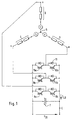
- Fig. 1 the equivalent circuit diagram of an electronically commutated synchronous motor is shown.
- the synchronous motor has three star-connected in its stator, not shown Winding strands 2, 3 and 4 on the one hand in a star point 5 and on the other hand each are connected to a connecting terminal u, v, w of the motor.
- the synchronous motor has also a rotor, not shown, which carries a permanent magnet.
- Fig. 1 shown embodiment is a three-strand, six-pulse Synchronous motor with permanent excitation.
- the present invention basically for all types of multi-phase synchronous motors is applicable and the circuits shown in Figs. 1 and 2 only one show preferred embodiment.
- An intermediate circuit capacitor 7, which serves as a smoothing capacitor for the intermediate circuit voltage U ZK, is connected in parallel with the connections of a constant current source or an intermediate circuit converter. Furthermore, a free-wheeling diode 11 with the opposite forward direction is connected in parallel with the switching means 8-10.
- Critical states can be, for example, an excessively high or too low intermediate circuit voltage U ZK or an overcurrent I LB in the circuit of the power bridge 7-11 critical conditions, both the intermediate circuit voltage U ZK and the current flowing in the power bridge 7-11 current I LB monitored and the determined measurement signals U ZK, and I LB is supplied to the motor control 12th in the critical case, the intermediate circuit voltage is generally slow growing, so that the engine controller 12 can respond in time.
- Fig. 2 the control of the switching means 8a and 8b is shown in more detail by way of example; the control of the other switching means 9a, 9b and 10a, 10b takes place in an analogous manner.
- the motor controller 12 has a default circuit 16 connected in the simplest, in Fig. 2 case shown from an additional power supply with the terminals 20 and 21.
- the upper switching means 8a is driven to a positive potential, for example + 5 V, and the actuation of the lower switching means 8b to basic potential, i.e. 0 V, laid.
Landscapes
- Engineering & Computer Science (AREA)
- Power Engineering (AREA)
- Control Of Ac Motors In General (AREA)
- Control Of Motors That Do Not Use Commutators (AREA)
- Stopping Of Electric Motors (AREA)
Applications Claiming Priority (2)
| Application Number | Priority Date | Filing Date | Title |
|---|---|---|---|
| DE19804967 | 1998-02-07 | ||
| DE19804967A DE19804967A1 (de) | 1998-02-07 | 1998-02-07 | Verfahren und Vorrichtung zur Steuerung eines Synchronmotors |
Publications (4)
| Publication Number | Publication Date |
|---|---|
| EP0935336A2 true EP0935336A2 (fr) | 1999-08-11 |
| EP0935336A3 EP0935336A3 (fr) | 2001-05-30 |
| EP0935336B1 EP0935336B1 (fr) | 2002-12-04 |
| EP0935336B2 EP0935336B2 (fr) | 2006-05-10 |
Family
ID=7856996
Family Applications (1)
| Application Number | Title | Priority Date | Filing Date |
|---|---|---|---|
| EP99102107A Expired - Lifetime EP0935336B2 (fr) | 1998-02-07 | 1999-02-03 | Méthode et dispositif de commande d' un moteur synchron |
Country Status (3)
| Country | Link |
|---|---|
| EP (1) | EP0935336B2 (fr) |
| DE (2) | DE19804967A1 (fr) |
| ES (1) | ES2189290T5 (fr) |
Cited By (8)
| Publication number | Priority date | Publication date | Assignee | Title |
|---|---|---|---|---|
| GB2338847B (en) * | 1998-05-12 | 2002-02-27 | Mannesmann Sachs Ag | Control system for a permanent magnet electric motor with at least one phase |
| DE10059173C5 (de) * | 2000-11-29 | 2004-07-15 | Siemens Ag | Antriebssteuerung für einen Drehstrommotor über einen Wechselrichter in sicherer Technik |
| EP1768251A1 (fr) * | 2005-09-21 | 2007-03-28 | International Rectifier Corporation | Circuit de protéction pour un moteur synchrone à aimants permanents en opération d'affaiblissement de champ |
| EP1655829A3 (fr) * | 2004-11-04 | 2009-01-14 | Diehl AKO Stiftung & Co. KG | Circuit et procédé pour le contrôle d'un moteur électrique, en praticulier d'une machine à laver |
| WO2013023807A3 (fr) * | 2011-08-18 | 2013-07-11 | Robert Bosch Gmbh | Circuit d'états de fonctionnement pour un onduleur et procédé de réglage des états de fonctionnement d'un onduleur |
| CN106226607A (zh) * | 2016-08-30 | 2016-12-14 | 广东威灵电机制造有限公司 | 无刷直流电机的故障检测方法及装置 |
| DE102015220910A1 (de) | 2015-10-27 | 2017-06-01 | BSH Hausgeräte GmbH | Spannungsüberwachung für eine Motoransteuerschaltung eines bürstenlosen Waschmaschinenmotors |
| EP3208906A1 (fr) * | 2016-02-17 | 2017-08-23 | Valeo Equipements Electriques Moteur | Système de commande d'un onduleur d'un moteur électrique, système de moteur comportant un tel système de commande |
Families Citing this family (7)
| Publication number | Priority date | Publication date | Assignee | Title |
|---|---|---|---|---|
| DE19905457A1 (de) * | 1999-02-11 | 2000-08-31 | Daimler Chrysler Ag | Vorrichtung und Verfahren zur Ansteuerung eines Pulswechselrichters zur Ansteuerung einer elektrischen Maschine |
| DE102007024178A1 (de) * | 2007-05-24 | 2008-11-27 | Converteam Gmbh | Verfahren zum Betreiben einer elektrischen Schaltung sowie entsprechende elektrische Schaltung |
| DE102011075789A1 (de) | 2011-05-13 | 2012-11-15 | Zf Friedrichshafen Ag | Verfahren zum Betrieb einer Drehfeldmaschine |
| DE102011089877A1 (de) * | 2011-12-23 | 2013-06-27 | Conti Temic Microelectronic Gmbh | Steuerschaltung zum Ansteuern eines elektrischen Konverters zum Antreiben einer elektrischen Maschine |
| DE102012208762B4 (de) * | 2012-05-24 | 2022-05-05 | Robert Bosch Gmbh | Verfahren zum Abbremsen einer Strömungsmaschine mit einer Synchronmaschine |
| US9054618B2 (en) | 2012-12-18 | 2015-06-09 | Infineon Technologies Austria Ag | Safety circuit and emergency power supply for gate control circuit |
| DE102015201524A1 (de) * | 2015-01-29 | 2016-08-04 | Zf Friedrichshafen Ag | Sicherheitsabschaltung eines Elektromotors |
Family Cites Families (6)
| Publication number | Priority date | Publication date | Assignee | Title |
|---|---|---|---|---|
| DE3139546A1 (de) * | 1981-10-05 | 1983-04-21 | Siemens AG, 1000 Berlin und 8000 München | Vier-quadrantensteller zur steuerung einer kollektorlosen gleichstrommaschine |
| DE3614093A1 (de) * | 1986-04-25 | 1987-11-05 | Quick Rotan Elektromotoren | Vorrichtung zum bremsen eines kommutatorlosen elektromotors |
| JP2536010B2 (ja) * | 1988-01-25 | 1996-09-18 | ティアツク株式会社 | 3相ブラシレスモ―タ装置 |
| WO1994007301A1 (fr) * | 1992-09-24 | 1994-03-31 | Siemens Aktiengesellschaft | Procede et dispositif de regulation d'un moteur synchrone a excitation continue alimente par un convertisseur |
| DE4442151A1 (de) * | 1994-11-26 | 1996-05-30 | Philips Patentverwaltung | Schaltungsanordnung zum Steuern eines elektronisch kommutierten Motors |
| JPH0947054A (ja) * | 1995-07-28 | 1997-02-14 | Fanuc Ltd | サーボモータのダイナミックブレーキ回路 |
-
1998
- 1998-02-07 DE DE19804967A patent/DE19804967A1/de not_active Withdrawn
-
1999
- 1999-02-03 ES ES99102107T patent/ES2189290T5/es not_active Expired - Lifetime
- 1999-02-03 DE DE59903608T patent/DE59903608D1/de not_active Expired - Lifetime
- 1999-02-03 EP EP99102107A patent/EP0935336B2/fr not_active Expired - Lifetime
Cited By (10)
| Publication number | Priority date | Publication date | Assignee | Title |
|---|---|---|---|---|
| GB2338847B (en) * | 1998-05-12 | 2002-02-27 | Mannesmann Sachs Ag | Control system for a permanent magnet electric motor with at least one phase |
| DE10059173C5 (de) * | 2000-11-29 | 2004-07-15 | Siemens Ag | Antriebssteuerung für einen Drehstrommotor über einen Wechselrichter in sicherer Technik |
| EP1655829A3 (fr) * | 2004-11-04 | 2009-01-14 | Diehl AKO Stiftung & Co. KG | Circuit et procédé pour le contrôle d'un moteur électrique, en praticulier d'une machine à laver |
| EP1768251A1 (fr) * | 2005-09-21 | 2007-03-28 | International Rectifier Corporation | Circuit de protéction pour un moteur synchrone à aimants permanents en opération d'affaiblissement de champ |
| US7554276B2 (en) | 2005-09-21 | 2009-06-30 | International Rectifier Corporation | Protection circuit for permanent magnet synchronous motor in field weakening operation |
| WO2013023807A3 (fr) * | 2011-08-18 | 2013-07-11 | Robert Bosch Gmbh | Circuit d'états de fonctionnement pour un onduleur et procédé de réglage des états de fonctionnement d'un onduleur |
| US9673744B2 (en) | 2011-08-18 | 2017-06-06 | Robert Bosch Gmbh | Operating state circuit for inverter and method for setting operating states of an inverter |
| DE102015220910A1 (de) | 2015-10-27 | 2017-06-01 | BSH Hausgeräte GmbH | Spannungsüberwachung für eine Motoransteuerschaltung eines bürstenlosen Waschmaschinenmotors |
| EP3208906A1 (fr) * | 2016-02-17 | 2017-08-23 | Valeo Equipements Electriques Moteur | Système de commande d'un onduleur d'un moteur électrique, système de moteur comportant un tel système de commande |
| CN106226607A (zh) * | 2016-08-30 | 2016-12-14 | 广东威灵电机制造有限公司 | 无刷直流电机的故障检测方法及装置 |
Also Published As
| Publication number | Publication date |
|---|---|
| EP0935336B2 (fr) | 2006-05-10 |
| DE59903608D1 (de) | 2003-01-16 |
| ES2189290T5 (es) | 2006-12-01 |
| EP0935336A3 (fr) | 2001-05-30 |
| ES2189290T3 (es) | 2003-07-01 |
| EP0935336B1 (fr) | 2002-12-04 |
| DE19804967A1 (de) | 1999-08-12 |
Similar Documents
| Publication | Publication Date | Title |
|---|---|---|
| EP1655829B1 (fr) | Circuit et procédé pour le contrôle d'un moteur électrique, en praticulier d'une machine à laver | |
| DE102014114122B4 (de) | Drehende elektrische Maschine, die an einem Fahrzeug befestigt ist | |
| EP0935336A2 (fr) | Méthode et dispositif de commande d' un moteur synchron | |
| WO2008138864A1 (fr) | Procédé et dispositif de fonctionnement d'une unité de commande pour commander une machine électrique | |
| DE102013216224A1 (de) | Verfahren und Vorrichtung zum Bestimmen von Phasenströmen und eines Erregerstroms einer elektrischen Maschine sowie Motorsystem | |
| DE112015006526T5 (de) | Wechselstrom-Drehelektromaschinen-Steuervorrichtung | |
| DE102021214534A1 (de) | Verfahren zum Betrieb einer elektrischen Maschine | |
| EP0471038B1 (fr) | Moteur a collecteur | |
| DE102018133248B4 (de) | Motorsteuervorrichtung und Steuerverfahren für Motorsteuervorrichtung | |
| EP2570291A1 (fr) | Système d'entraînement d'un véhicule fonctionnant sur batterie doté d'une machine synchrone à excitation permanente alimentée par convertisseur | |
| EP2534750B1 (fr) | Procédé pour réduire le courant de démarrage d'une machine polyphasée fonctionnant par commutation en bloc | |
| EP2499727A2 (fr) | Ensemble interrupteur de puissance pour un onduleur | |
| EP2499730A2 (fr) | Onduleur avec circuit de calage de tension | |
| WO2015000669A1 (fr) | Procédé permettant d'éviter les couples freineurs dans des machines synchrones à excitation permanente | |
| EP3695509B1 (fr) | Procédé pour effectuer un changement entre une commande par bloc et une commande par mli d'une machine électrique | |
| EP0903007B1 (fr) | Systeme comportant un moteur a commutation electronique | |
| EP2570290A1 (fr) | Système d'entraînement d'un véhicule fonctionnant sur batterie doté d'une machine synchrone à excitation permanente alimentée par convertisseur | |
| EP2499729A2 (fr) | Onduleur avec circuit de calage de tension | |
| DE102011085657A1 (de) | Verfahren und Vorrichtung zum Betreiben einer elektronisch kommutierten elektrischen Maschine in einem Fehlerfall | |
| DE102014223224A1 (de) | Antriebseinrichtung und Verfahren zum Betrieb einer Antriebseinrichtung | |
| DE102017130869A1 (de) | Elektrisches Getriebe und Verfahren zum Betreiben eines Elektromotors | |
| EP3172831A1 (fr) | Procédé de commande d'au moins une machine électrique pouvant fonctionner en générateur et moyen pour mettre en oeuvre celui-ci | |
| DE10114973B4 (de) | Werkzeugmaschine mit Spindel mit einer Vorrichtung zur Änderung der Speisespannung | |
| DE102007019990B4 (de) | Kfz-Generator mit externem Regler | |
| EP3386097A1 (fr) | Circuit d'alimentation sélective des moteurs en énergie |
Legal Events
| Date | Code | Title | Description |
|---|---|---|---|
| PUAI | Public reference made under article 153(3) epc to a published international application that has entered the european phase |
Free format text: ORIGINAL CODE: 0009012 |
|
| AK | Designated contracting states |
Kind code of ref document: A2 Designated state(s): DE ES FR GB IT |
|
| AX | Request for extension of the european patent |
Free format text: AL;LT;LV;MK;RO;SI |
|
| RAP1 | Party data changed (applicant data changed or rights of an application transferred) |
Owner name: DIEHL AKO STIFTUNG & CO. KG |
|
| PUAL | Search report despatched |
Free format text: ORIGINAL CODE: 0009013 |
|
| AK | Designated contracting states |
Kind code of ref document: A3 Designated state(s): AT BE CH CY DE DK ES FI FR GB GR IE IT LI LU MC NL PT SE |
|
| AX | Request for extension of the european patent |
Free format text: AL;LT;LV;MK;RO;SI |
|
| 17P | Request for examination filed |
Effective date: 20010509 |
|
| 17Q | First examination report despatched |
Effective date: 20011227 |
|
| AKX | Designation fees paid |
Free format text: DE ES FR GB IT |
|
| GRAG | Despatch of communication of intention to grant |
Free format text: ORIGINAL CODE: EPIDOS AGRA |
|
| GRAG | Despatch of communication of intention to grant |
Free format text: ORIGINAL CODE: EPIDOS AGRA |
|
| GRAH | Despatch of communication of intention to grant a patent |
Free format text: ORIGINAL CODE: EPIDOS IGRA |
|
| GRAH | Despatch of communication of intention to grant a patent |
Free format text: ORIGINAL CODE: EPIDOS IGRA |
|
| GRAA | (expected) grant |
Free format text: ORIGINAL CODE: 0009210 |
|
| AK | Designated contracting states |
Kind code of ref document: B1 Designated state(s): DE ES FR GB IT |
|
| REG | Reference to a national code |
Ref country code: GB Ref legal event code: FG4D Free format text: NOT ENGLISH |
|
| REF | Corresponds to: |
Ref document number: 59903608 Country of ref document: DE Date of ref document: 20030116 |
|
| GBT | Gb: translation of ep patent filed (gb section 77(6)(a)/1977) |
Effective date: 20030401 |
|
| PLBI | Opposition filed |
Free format text: ORIGINAL CODE: 0009260 |
|
| REG | Reference to a national code |
Ref country code: ES Ref legal event code: FG2A Ref document number: 2189290 Country of ref document: ES Kind code of ref document: T3 |
|
| ET | Fr: translation filed | ||
| PLBI | Opposition filed |
Free format text: ORIGINAL CODE: 0009260 |
|
| 26 | Opposition filed |
Opponent name: SIEMENS AG Effective date: 20030612 |
|
| PLBI | Opposition filed |
Free format text: ORIGINAL CODE: 0009260 |
|
| 26 | Opposition filed |
Opponent name: DAIMLERCHRYSLER AG Effective date: 20030722 Opponent name: SIEMENS AG Effective date: 20030612 |
|
| 26 | Opposition filed |
Opponent name: ZF SACHS AG Effective date: 20030731 Opponent name: DAIMLERCHRYSLER AG Effective date: 20030722 Opponent name: SIEMENS AG Effective date: 20030612 |
|
| PLAX | Notice of opposition and request to file observation + time limit sent |
Free format text: ORIGINAL CODE: EPIDOSNOBS2 |
|
| PLBB | Reply of patent proprietor to notice(s) of opposition received |
Free format text: ORIGINAL CODE: EPIDOSNOBS3 |
|
| PUAH | Patent maintained in amended form |
Free format text: ORIGINAL CODE: 0009272 |
|
| STAA | Information on the status of an ep patent application or granted ep patent |
Free format text: STATUS: PATENT MAINTAINED AS AMENDED |
|
| 27A | Patent maintained in amended form |
Effective date: 20060510 |
|
| AK | Designated contracting states |
Kind code of ref document: B2 Designated state(s): DE ES FR GB IT |
|
| GBTA | Gb: translation of amended ep patent filed (gb section 77(6)(b)/1977) |
Effective date: 20060621 |
|
| GBTA | Gb: translation of amended ep patent filed (gb section 77(6)(b)/1977) |
Effective date: 20060628 |
|
| ET3 | Fr: translation filed ** decision concerning opposition | ||
| REG | Reference to a national code |
Ref country code: ES Ref legal event code: DC2A Date of ref document: 20060719 Kind code of ref document: T5 |
|
| PGFP | Annual fee paid to national office [announced via postgrant information from national office to epo] |
Ref country code: GB Payment date: 20080201 Year of fee payment: 10 |
|
| PLAB | Opposition data, opponent's data or that of the opponent's representative modified |
Free format text: ORIGINAL CODE: 0009299OPPO |
|
| GBPC | Gb: european patent ceased through non-payment of renewal fee |
Effective date: 20090203 |
|
| PG25 | Lapsed in a contracting state [announced via postgrant information from national office to epo] |
Ref country code: GB Free format text: LAPSE BECAUSE OF NON-PAYMENT OF DUE FEES Effective date: 20090203 |
|
| REG | Reference to a national code |
Ref country code: FR Ref legal event code: PLFP Year of fee payment: 17 |
|
| PGFP | Annual fee paid to national office [announced via postgrant information from national office to epo] |
Ref country code: IT Payment date: 20150226 Year of fee payment: 17 Ref country code: ES Payment date: 20150225 Year of fee payment: 17 |
|
| PGFP | Annual fee paid to national office [announced via postgrant information from national office to epo] |
Ref country code: FR Payment date: 20150219 Year of fee payment: 17 |
|
| PGFP | Annual fee paid to national office [announced via postgrant information from national office to epo] |
Ref country code: DE Payment date: 20150422 Year of fee payment: 17 |
|
| REG | Reference to a national code |
Ref country code: DE Ref legal event code: R119 Ref document number: 59903608 Country of ref document: DE |
|
| REG | Reference to a national code |
Ref country code: FR Ref legal event code: ST Effective date: 20161028 |
|
| PG25 | Lapsed in a contracting state [announced via postgrant information from national office to epo] |
Ref country code: IT Free format text: LAPSE BECAUSE OF NON-PAYMENT OF DUE FEES Effective date: 20160203 |
|
| PG25 | Lapsed in a contracting state [announced via postgrant information from national office to epo] |
Ref country code: FR Free format text: LAPSE BECAUSE OF NON-PAYMENT OF DUE FEES Effective date: 20160229 Ref country code: DE Free format text: LAPSE BECAUSE OF NON-PAYMENT OF DUE FEES Effective date: 20160901 |
|
| PG25 | Lapsed in a contracting state [announced via postgrant information from national office to epo] |
Ref country code: ES Free format text: LAPSE BECAUSE OF NON-PAYMENT OF DUE FEES Effective date: 20160204 |