EP0935434B1 - Support de presentation pour documents ou analogues - Google Patents
Support de presentation pour documents ou analogues Download PDFInfo
- Publication number
- EP0935434B1 EP0935434B1 EP97912277A EP97912277A EP0935434B1 EP 0935434 B1 EP0935434 B1 EP 0935434B1 EP 97912277 A EP97912277 A EP 97912277A EP 97912277 A EP97912277 A EP 97912277A EP 0935434 B1 EP0935434 B1 EP 0935434B1
- Authority
- EP
- European Patent Office
- Prior art keywords
- documents
- support
- clip
- bearing surface
- support according
- Prior art date
- Legal status (The legal status is an assumption and is not a legal conclusion. Google has not performed a legal analysis and makes no representation as to the accuracy of the status listed.)
- Expired - Lifetime
Links
- 238000003780 insertion Methods 0.000 claims description 4
- 230000037431 insertion Effects 0.000 claims description 4
- 238000002347 injection Methods 0.000 claims description 2
- 239000007924 injection Substances 0.000 claims description 2
- 239000000463 material Substances 0.000 description 3
- 229920003023 plastic Polymers 0.000 description 3
- 238000005452 bending Methods 0.000 description 2
- 230000001627 detrimental effect Effects 0.000 description 2
- 238000012423 maintenance Methods 0.000 description 2
- 238000000034 method Methods 0.000 description 2
- 238000007665 sagging Methods 0.000 description 2
- 238000004804 winding Methods 0.000 description 2
- 230000006866 deterioration Effects 0.000 description 1
- 238000005259 measurement Methods 0.000 description 1
- 230000000630 rising effect Effects 0.000 description 1
- 239000007787 solid Substances 0.000 description 1
- 238000013519 translation Methods 0.000 description 1
Images


Classifications
-
- A—HUMAN NECESSITIES
- A47—FURNITURE; DOMESTIC ARTICLES OR APPLIANCES; COFFEE MILLS; SPICE MILLS; SUCTION CLEANERS IN GENERAL
- A47F—SPECIAL FURNITURE, FITTINGS, OR ACCESSORIES FOR SHOPS, STOREHOUSES, BARS, RESTAURANTS OR THE LIKE; PAYING COUNTERS
- A47F7/00—Show stands, hangers, or shelves, adapted for particular articles or materials
- A47F7/14—Show stands, hangers, or shelves, adapted for particular articles or materials for pictures, e.g. in combination with books or seed-bags ; for cards, magazines, newspapers, books or booklike articles, e.g. audio/video cassettes
- A47F7/146—Show stands, hangers, or shelves, adapted for particular articles or materials for pictures, e.g. in combination with books or seed-bags ; for cards, magazines, newspapers, books or booklike articles, e.g. audio/video cassettes the show stands or the like being provided with compartments or pockets
- A47F7/147—Show stands, hangers, or shelves, adapted for particular articles or materials for pictures, e.g. in combination with books or seed-bags ; for cards, magazines, newspapers, books or booklike articles, e.g. audio/video cassettes the show stands or the like being provided with compartments or pockets being individually detachable
Definitions
- the present invention relates to the technical field of support, selection or presentation of flat articles or documents of a more less flexible or flexible, such as leaflets, sheets, leaflets, brochures, booklets, prints, etc.
- the object of the invention relates more precisely to the supports comprising at minus a clamp adapted to keep the documents in a stable position.
- a housing comprising a base from which rises a bottom panel and a facade panel interconnected by side walls.
- the housing is open from above to allow the insertion and taking of documents based by their edge on the base.
- This type of support has a major drawback related to the relative freedom of orientation that the documents have inside the case.
- the documents can take biased directions or sag as they go measurement of document collection, which hinders the presentation of documents and causes their deterioration.
- patent EP 0 466 697 has proposed a support for documents comprising a bottom panel rising from a base serving as support for the edge of the documents.
- This support also includes a clamp extending from the base in a curved orientation directed towards an opening in the bottom panel.
- This clamp has an elastic tension adapted to allow retaining various thicknesses of documents.
- the elastic tension of the clamp also produces in documents, a concave curvature directed over a limited width, on either side of their vertical median, extending from top to bottom of the documents.
- the curvature of the documents gives them a self-supporting structure making it possible to avoid the problems of sagging and winding of the documents.
- the object of the invention therefore aims to remedy the drawbacks mentioned above by proposing a support for documents in the general sense, designed for maintain a stable position over time regardless of the amount of documents remaining, while providing a neat presentation of documents.
- Fig. 1 is a perspective view showing a first embodiment of a support for documents according to the invention.
- Fig. 2 is a sectional elevation view taken substantially along lines II-II of FIG. 1.
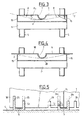
- Fig. 3 is a cross-sectional view taken substantially along lines III-III of FIG. 2.
- Fig. 4 is a cross-sectional view illustrating another alternative embodiment of a support according to the invention.
- Fig. 5 is a section showing a characteristic detail of the invention.
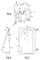
- Fig. 6 is a perspective view showing another embodiment of a support according to the invention.
- Fig. 7 is a front view of another alternative embodiment of a support according to the invention.
- Fig. 8 is a side view taken substantially along lines VIII-VIII of FIG. 7.
- the subject of the invention relates to a support or a display 1 intended to ensure the maintenance in a stable position, of documents 2 in the general sense, such as printed matter, sheets, sheets, booklets, brochures, leaflets or the like .
- the support 1 comprises a base 3 intended to serve as a support for the lower edge of the documents 2 .
- the base 3 is mounted on a base 4 constituted by two feet 5 , a detailed description of which will be given later.
- the support 1 comprises a bottom 6 constituted, in the example illustrated, by a central support 7 for the back of the documents 2 .
- the central support 7 extends projecting between two lateral clearances 8 being established on either side of the support 7 .
- the central support 7 rises from the base 3 , in a substantially perpendicular direction.
- the central support 7 constitutes a rib having a curved cross section.
- the rib 7 has a profile forming a localized support for the back of the documents.
- the rib 7 may have a profile with a larger radius of curvature, adapted to allow support for the documents, not located, but extending over part of the width of the documents.
- the profile of the support 7 may have a curvature substantially identical to that of the documents 2, shown in phantom in FIG. 3.
- the support 7 may consist of several juxtaposed ribs, the extreme ribs delimiting towards the outside, the lateral clearances 8 .
- the support 7 is located, in the examples illustrated, to allow the support of the documents substantially in their plane of vertical symmetry.
- the support 7 is not necessarily located to allow the centered support of the documents, but is adapted to act in the central region of the documents which can extend over most of their width.
- the central support 7 preferably has a free end 9 having a curved profile towards the bottom 6 and whose function will appear more clearly in the following description.
- the support 1 also comprises at least one clamp 11 having a substantially uniform thickness and extending from the base 3 with a profile 12 curved outwards and upwards, extended by a flat section 13 directed upwards and towards the bottom 6.
- the clamp 11 thus constitutes the front of the support.
- the clamp 11 defines with the bottom 6 , an open cavity 14 for receiving documents 2 which are subject to the elastic tension developed by the clamp forming a spring.
- the clamp 11 is provided with two lateral pressure elements 15 extending in the absence of documents 2 , each inside a lateral clearance 8.
- each lateral pressure element 15 is formed by means of a fin extending perpendicularly to the clamp 11 .
- the fins 15 are shaped so that their upper edges 15 1 are inclined downward from the back of the clamp 11 to facilitate the introduction of documents inside the receiving cavity 14 . as shown more clearly in fig. 3, the free ends of the pressure elements 15 extend in the recesses 8 beyond the vertical plane P tangent to the central support 7.
- the distance l between the vertical plane P tangent to the central support 7 and the plane P 1 passing through the ends of the pressure elements 15, is chosen to generate a radius of curvature adapted to ensure the stability of the documents. This distance can usually be of the order of 5 to 10 mm.
- Such an arrangement makes it possible to ensure on the documents 2 two pressure points situated laterally with respect to the central zone of the documents abutted by their backs on the central support 7 . It follows that the documents 2 are folded with a convex curvature extending from top to bottom of the documents and directed from one vertical edge to the other of the documents. Relative to the clamp 11 or to the support front, the vertical edges of the documents are thrown back in consideration of the central part of the documents.
- the curvature of the documents 2 gives them a self-supporting structure excluding the problems of winding or sagging of the documents.
- a convex curvature makes it possible to avoid a forward bending of the upper corners of the documents and, as a result, localized folds detrimental to reading and presentation aesthetics.
- the central support 7 extends over a length much greater than the pressure elements 15 which are of a point or almost localized nature.
- the pressure elements 15 must be located on either side of the central support 7 , extending substantially along the same level.
- the support 1 comprises a bottom 6 materialized by a panel or a wall 18 from which projects, the central support 7 (fig. 4).
- the pressure elements 15 ensure that the vertical edges of the documents 2 are pressed against the bottom panel 18 .
- the vertical edges of the documents 2 are thus pressed over their entire height against the bottom panel 18 , even when pressure elements of a punctual nature are used. Due to the convex curvature of the documents 2 and the support of the lateral edges over their entire height, this results in a stable maintenance of the documents over time and a perfect presentation, whatever the number of documents remaining.
- the support 1 is made of an injected plastic material using a single translation mold making it possible to obtain respectively front and bottom walls, located in offset planes.
- the clamp 11 and the central support 7 extend from the base 3 to form a single piece.
- the clamp 11 has a central opening 20 whose profile corresponds to that of the support 7 . More specifically, the width of the opening 20 is greater than the width of the central support 7 , while the height of the opening 20 is substantially greater than the height of the central support 7 .
- the opening 20 thus delimits on either side, two arms 21 each corresponding to a lateral clearance 8 .
- the two arms 21 are connected to each other at their top by a connection part 22 which is established above the central support 7 and makes it possible to produce a single clamp 11. It should be noted that the arms 21 can be independent of each other, so that the support 1 comprises two clamps each formed by an arm 21 provided with a lateral pressure element 15.
- the clamp 11 defines, between its connection part 22 and the upper end 9 of the central support 7 , a window or an opening 23 for introducing documents 2 .
- the curved or rounded profile of the top of the central support 7 possibly combined with the upper edges 15 1 of the pressure elements, facilitate the introduction of the documents 2 inside the receiving cavity 14.
- the support 1 is supported by a base 4 intended to rest on a horizontal support plane S.
- the base 4 is made up, as is shown more precisely in FIGS. 1 and 5, by two feet 5, for example of removable nature, each provided with two notches 25 each arranged in a wing 5 1 extending from the core of the foot.
- the notches 25 of each foot 5 are intended to cooperate with a pair of notches 26, 26 1 arranged on the bottom wall 18 (fig. 5) or on a fallen return 27 extending from the base 3 ( fig. 1).
- the notches 26, 26 1 are formed one with respect to the other and with respect to the edges of the support 1 , so as to allow an assembly of at least two supports 1 mounted side by side .
- the distance l 1 between the notch closest to the edge 1 1 namely that 26 1 and the edge l 1
- the distance l 1 between the notch closest to the edge 1 1 is equal to half the distance l 2 separating the two notches 26, 26 1 of the same pair.
- Such a characteristic allows the adjoining assembly of several similar supports 1 by mounting a foot 5 straddling two supports 1, coming to engage by its notches 25 in the notches 26 1 of the supports, placed closest to the edges 1 1 . It should be noted that the material remaining between the two notches 26, 26 1 of the same pair can be eliminated, making it possible to obtain a single notch of larger dimension.
- the support 1 can be mounted on a base 4 of different structure from that described above.
- the support 1 can be equipped with fixing means on a wall support or on a bottom panel 18 intended to be mounted on a wall support.
- the bottom panel 18, or even the support can be provided with lateral walls extending perpendicular to the bottom 6, so as to serve as a lateral stop for the documents 2 .
- the support 1 can have different possible forms while assuming the functions described above.
- provision may be made to make a support 1 comprising a single clamp 11 having a solid surface while being produced by an injection technique.
- the support 1 comprises a bottom panel 18 from which extends a central support 7 constituted by a rib.
- the bottom panel 18 has a main opening 30 arranged to allow the lateral clearances 8 to remain on either side of the lower end of the support 7 .
- the main opening 30 associated with the openings 8 defines an open U-shaped section corresponding to the profile of the clamp 11 which extends from the bottom panel 18 from the base of the opening 30.
- the clamp 11 has two pressure elements 15 placed in correspondence with the lateral clearances 8 .
- the pressure elements 15 may be constituted by added elements or by a suitable curvature of the clamp, namely convex. It should be noted that the convex shape given to the clamp 11 makes it possible to increase the dimensions of the window 23 for introducing the documents.
- the support 1 comprises, on either side, side walls 37 ensuring the abutment of the documents 2 by their vertical edges.
- the bottom panel 18 and / or the side walls 37 can be provided with means 38 ensuring the fixing of the display stand on a vertical support or its assembly with one or more identical supports 1 mounted adjacent.
- the support 1 according to the invention is made of an injected plastic.
- the support 1 according to the invention namely the clamp (s) 11 , the bottom panel 18 and the central support 7
- the support 1 can be manufactured by a different technique for example, by folding.
- the support 1 comprises a single clamp 11 having a base 3 intended to be fixed on a bottom panel 18.
- the bottom panel 18 is equipped with a central support 7 delimiting, on either side, lateral clearances 8 , in each of which is intended to come a lateral pressure element 15 carried by the clamp.
- the pressure elements 15 may be constituted by fins added or formed by bending from the clamp or by a projecting imprint formed, for example, by stamping.
- the central support 7 extends over a limited height relative to the height of the document. Such an arrangement is sufficient to impart a convex curvature to the document.
- the clamp 11 has a substantially straight free end 22 . Provision may be made at this end for a cutout 40 of triangular shape shown diagrammatically in phantom in FIG. 7, making it possible to accentuate the window for introducing documents 23 . In the same direction, provision may be made to give the clamp 11 a convex profile to facilitate the introduction of documents between the clamp and the central support 7 .
- the support 1 according to the invention is preferably made of a transparent plastic material, so that the clamp (s) 11 do not hide the documents.
- provision may be made to attach to the clamp 11 and, in particular, between the arms 21, a part intended to receive a message of an advertising nature or not.
- the support according to the invention makes it possible to present any document to flat character in a stable position does not affect their integrity whatever the number of documents remaining in the medium.
Landscapes
- Sheet Holders (AREA)
Description
- une embase destinée à servir d'appui pour les documents,
- un fond surélevé par rapport à l'embase et assurant un appui pour le dos des documents,
- et au moins une pince s'étendant à partir de l'embase en étant courbée en direction du fond.
- un fond aménagé pour constituer un appui central pour le dos des documents, s'établissant en saillie entre deux dégagements latéraux,
- et deux éléments latéraux de pression portés par la ou les pinces en s'étendant, en l'absence de documents, à l'intérieur des dégagements latéraux, de façon que des documents placés entre l'appui central et les éléments latéraux de pression, présentent une courbure convexe d'un bord vertical à l'autre.
Claims (12)
- Support de présentation pour documents (2) ou analogues comportant :caractérisé en ce :une embase (3) destinée à servir d'appui pour les documents (2),un fond (6) surélevé par rapport à l'embase et assurant un appui pour le dos des documents,et au moins une pince (11) s'étendant à partir de l'embase (3) en étant courbée en direction du fond (6),le fond (6) est aménagé pour constituer un appui central (7) pour le dos des documents, s'établissant en saillie entre deux dégagements latéraux (8),et en ce que la ou les pinces (11) porte(nt) deux éléments latéraux de pression (15) s'étendant, en l'absence de documents, à l'intérieur des dégagements latéraux (8), de façon que des documents placés entre l'appui central (7) et les éléments latéraux de pression (15), présentent une courbure convexe d'un bord vertical à l'autre.
- Support selon la revendication 1, caractérisé en ce que le fond (6) est aménagé pour constituer un appui central (7) s'élevant en saillie par rapport à un panneau de support (18) sur lequel viennent en appui les bords verticaux des documents.
- Support selon la revendication 2, caractérisé en ce que le panneau de support (18) est délimité, de part et d'autre, par des parois latérales (37) servant de butée latérale pour les documents.
- Support selon la revendication 1 ou 2, caractérisé en ce que l'appui central (7) présente à sa partie supérieure (8), un profil incurvé en direction opposée de la pince pour constituer, entre la pince (11) et l'appui central (7), une fenêtre (23) d'introduction des documents.
- Support selon la revendication 1 ou 2, caractérisé en ce que la ou les pinces (11) possèdent transversalement un profil convexe par rapport à l'appui central, en vue de délimiter, entre ce dernier et la ou les pinces, une fenêtre d'introduction (23) des documents, les bords extrêmes de la ou des pinces délimitant les éléments latéraux de pression (15).
- Support selon la revendication 1, caractérisé en ce que les éléments latéraux de pression (15) sont constitués par des ailettes s'étendant en saillie à partir de la ou des pinces (11) et présentant un bord supérieur (151) incliné pour faciliter l'introduction des documents.
- Support selon l'une des revendications 1 à 6, caractérisé en ce que les deux éléments latéraux de pression (15) sont portés par une pince unique (11) présentant une ouverture centrale (20) correspondant à l'appui central et délimitée, de part et d'autre, par des bras (21) reliés à leur sommet et correspondant aux dégagements latéraux (8).
- Support selon la revendication 7, caractérisé en ce que la pince (11) et l'appui central (7) s'étendent à partir de l'embase (3) pour former une pièce unique réalisée par injection.
- Support selon l'une des revendications 1 à 6, caractérisé en ce que la ou les pinces (11), le panneau de fond (18) et l'appui central (7) sont réalisés par pliage.
- Support selon l'une des revendications 1 à 9, caractérisé en ce qu'il comporte un socle (4) de montage pour l'embase.
- Support selon la revendication 10, caractérisé en ce que le socle est formé par deux pieds (5) pourvus de deux encoches (25), destinés à être engagés chacun dans deux entailles (26) aménagées dans l'embase (3), la distance des entailles par rapport aux bords du panneau est déterminée de façon que chaque pied puisse supporter deux supports de présentation accolés.
- Support selon l'une des revendications 1 à 9, caractérisé en ce qu'il comporte des moyens (38) de fixation sur un support vertical.
Applications Claiming Priority (3)
| Application Number | Priority Date | Filing Date | Title |
|---|---|---|---|
| FR9613474A FR2754993B1 (fr) | 1996-10-29 | 1996-10-29 | Support de presentation pour documents ou analogues |
| FR9613474 | 1996-10-29 | ||
| PCT/FR1997/001937 WO1998018369A1 (fr) | 1996-10-29 | 1997-10-29 | Support de presentation pour documents ou analogues |
Publications (2)
| Publication Number | Publication Date |
|---|---|
| EP0935434A1 EP0935434A1 (fr) | 1999-08-18 |
| EP0935434B1 true EP0935434B1 (fr) | 2001-04-04 |
Family
ID=9497338
Family Applications (1)
| Application Number | Title | Priority Date | Filing Date |
|---|---|---|---|
| EP97912277A Expired - Lifetime EP0935434B1 (fr) | 1996-10-29 | 1997-10-29 | Support de presentation pour documents ou analogues |
Country Status (5)
| Country | Link |
|---|---|
| EP (1) | EP0935434B1 (fr) |
| DE (1) | DE69704497T2 (fr) |
| ES (1) | ES2158525T3 (fr) |
| FR (1) | FR2754993B1 (fr) |
| WO (1) | WO1998018369A1 (fr) |
Families Citing this family (1)
| Publication number | Priority date | Publication date | Assignee | Title |
|---|---|---|---|---|
| FR2796539B1 (fr) | 1999-07-21 | 2001-10-12 | Torenco Sarl | Procede pour realiser un support de presentation de documents et support de presentation pour de tels documents |
Family Cites Families (3)
| Publication number | Priority date | Publication date | Assignee | Title |
|---|---|---|---|---|
| US4332362A (en) * | 1980-03-10 | 1982-06-01 | The Cloverline Inc. | Telephone note clip |
| US4706342A (en) * | 1987-06-05 | 1987-11-17 | Yu Wen C | Paper clip |
| US4908912A (en) * | 1988-06-15 | 1990-03-20 | Grant Michael J | Retainer for maintaining a book in an open position |
-
1996
- 1996-10-29 FR FR9613474A patent/FR2754993B1/fr not_active Expired - Lifetime
-
1997
- 1997-10-29 EP EP97912277A patent/EP0935434B1/fr not_active Expired - Lifetime
- 1997-10-29 WO PCT/FR1997/001937 patent/WO1998018369A1/fr not_active Ceased
- 1997-10-29 DE DE69704497T patent/DE69704497T2/de not_active Expired - Fee Related
- 1997-10-29 ES ES97912277T patent/ES2158525T3/es not_active Expired - Lifetime
Also Published As
| Publication number | Publication date |
|---|---|
| FR2754993A1 (fr) | 1998-04-30 |
| DE69704497D1 (de) | 2001-05-10 |
| FR2754993B1 (fr) | 1999-01-15 |
| WO1998018369A1 (fr) | 1998-05-07 |
| EP0935434A1 (fr) | 1999-08-18 |
| ES2158525T3 (es) | 2001-09-01 |
| DE69704497T2 (de) | 2001-08-09 |
Similar Documents
| Publication | Publication Date | Title |
|---|---|---|
| FR2665422A1 (fr) | Montant reglable de support de corbeilles a courrier. | |
| WO2000027005A1 (fr) | Dispositif de fixation d'un fil sur un element porteur muni d'au moins une ouverture et ensemble porteur pour chemin de cables comportant au moins un tel dispositif | |
| FR2680030A1 (fr) | Presentoir en carton. | |
| FR2738104A1 (fr) | Chassis de support, notamment pour appareillages electriques | |
| EP0028564A1 (fr) | Siège de véhicule présentant au moins une coque d'assise | |
| EP0935434A1 (fr) | Support de presentation pour documents ou analogues | |
| EP0741645B1 (fr) | Presentoir de documents | |
| EP0134170A1 (fr) | Reliure mobile | |
| FR2714803A1 (fr) | Etagère à piliers rigidifiants. | |
| EP4183956B1 (fr) | Plaque de soubassement pour clôture et clôture correspondante | |
| EP0725467B1 (fr) | Dispositif de fixation pour l'assemblage des chemins de câbles en tÔle d'acier | |
| FR2519243A1 (fr) | Rayonnage | |
| EP1022833B1 (fr) | Adaptateur pour support de mécanisme, et support de mécanisme équipé d'au moins un tel adaptateur, notamment pour appareillage électrique | |
| FR2591255A1 (fr) | Element d'aeration et de desaeration pour des bandes de montage de toitures | |
| BE729698A (fr) | ||
| FR2657380A1 (fr) | Agrafe pour la mise en place d'un habillage sur un profile presentant au moins une aile. | |
| FR2796535A1 (fr) | Dispositif de support d'etageres reglable en hauteur a creneaux | |
| EP0891731B1 (fr) | Dispositif de fixation d'embouts de support de lattes transversales d'un sommier de literie | |
| EP1634512A1 (fr) | Tablette de rayonnage à faible charge pour présentoir en grande distribution | |
| FR3090980A1 (fr) | Système comportant une tablette et un dispositif porte-étiquette, configuré pour équiper un dispositif de présentation d’articles de marchandises | |
| FR2715640A1 (fr) | Présentoir multifonctions pour articles de lingerie. | |
| FR2684617A1 (fr) | Retroviseur pour un vehicule. | |
| BE1001654A6 (fr) | Boitier pour composants electroniques. | |
| EP1228790A1 (fr) | Table de travail pliante pour skis | |
| FR2719410A1 (fr) | Dispositif de fixation de support d'information. |
Legal Events
| Date | Code | Title | Description |
|---|---|---|---|
| PUAI | Public reference made under article 153(3) epc to a published international application that has entered the european phase |
Free format text: ORIGINAL CODE: 0009012 |
|
| 17P | Request for examination filed |
Effective date: 19990419 |
|
| AK | Designated contracting states |
Kind code of ref document: A1 Designated state(s): DE ES GB IT |
|
| GRAG | Despatch of communication of intention to grant |
Free format text: ORIGINAL CODE: EPIDOS AGRA |
|
| 17Q | First examination report despatched |
Effective date: 20000210 |
|
| GRAG | Despatch of communication of intention to grant |
Free format text: ORIGINAL CODE: EPIDOS AGRA |
|
| GRAH | Despatch of communication of intention to grant a patent |
Free format text: ORIGINAL CODE: EPIDOS IGRA |
|
| GRAH | Despatch of communication of intention to grant a patent |
Free format text: ORIGINAL CODE: EPIDOS IGRA |
|
| GRAA | (expected) grant |
Free format text: ORIGINAL CODE: 0009210 |
|
| AK | Designated contracting states |
Kind code of ref document: B1 Designated state(s): DE ES GB IT |
|
| REF | Corresponds to: |
Ref document number: 69704497 Country of ref document: DE Date of ref document: 20010510 |
|
| ITF | It: translation for a ep patent filed | ||
| GBT | Gb: translation of ep patent filed (gb section 77(6)(a)/1977) |
Effective date: 20010524 |
|
| REG | Reference to a national code |
Ref country code: ES Ref legal event code: FG2A Ref document number: 2158525 Country of ref document: ES Kind code of ref document: T3 |
|
| REG | Reference to a national code |
Ref country code: GB Ref legal event code: IF02 |
|
| PLBE | No opposition filed within time limit |
Free format text: ORIGINAL CODE: 0009261 |
|
| STAA | Information on the status of an ep patent application or granted ep patent |
Free format text: STATUS: NO OPPOSITION FILED WITHIN TIME LIMIT |
|
| 26N | No opposition filed | ||
| PGFP | Annual fee paid to national office [announced via postgrant information from national office to epo] |
Ref country code: GB Payment date: 20051020 Year of fee payment: 9 |
|
| PGFP | Annual fee paid to national office [announced via postgrant information from national office to epo] |
Ref country code: ES Payment date: 20051031 Year of fee payment: 9 |
|
| PGFP | Annual fee paid to national office [announced via postgrant information from national office to epo] |
Ref country code: IT Payment date: 20061031 Year of fee payment: 10 |
|
| GBPC | Gb: european patent ceased through non-payment of renewal fee |
Effective date: 20061029 |
|
| PG25 | Lapsed in a contracting state [announced via postgrant information from national office to epo] |
Ref country code: GB Free format text: LAPSE BECAUSE OF NON-PAYMENT OF DUE FEES Effective date: 20061029 |
|
| REG | Reference to a national code |
Ref country code: ES Ref legal event code: FD2A Effective date: 20061030 |
|
| PG25 | Lapsed in a contracting state [announced via postgrant information from national office to epo] |
Ref country code: ES Free format text: LAPSE BECAUSE OF NON-PAYMENT OF DUE FEES Effective date: 20061030 |
|
| PG25 | Lapsed in a contracting state [announced via postgrant information from national office to epo] |
Ref country code: IT Free format text: LAPSE BECAUSE OF NON-PAYMENT OF DUE FEES Effective date: 20071029 |
|
| PGFP | Annual fee paid to national office [announced via postgrant information from national office to epo] |
Ref country code: DE Payment date: 20090416 Year of fee payment: 12 |
|
| PG25 | Lapsed in a contracting state [announced via postgrant information from national office to epo] |
Ref country code: DE Free format text: LAPSE BECAUSE OF NON-PAYMENT OF DUE FEES Effective date: 20100501 |