EP0935507B1 - Verfahren zum herstellen von zuschnitten für zangenteile - Google Patents
Verfahren zum herstellen von zuschnitten für zangenteile Download PDFInfo
- Publication number
- EP0935507B1 EP0935507B1 EP97943040A EP97943040A EP0935507B1 EP 0935507 B1 EP0935507 B1 EP 0935507B1 EP 97943040 A EP97943040 A EP 97943040A EP 97943040 A EP97943040 A EP 97943040A EP 0935507 B1 EP0935507 B1 EP 0935507B1
- Authority
- EP
- European Patent Office
- Prior art keywords
- section
- process according
- profile
- blank
- pliers
- Prior art date
- Legal status (The legal status is an assumption and is not a legal conclusion. Google has not performed a legal analysis and makes no representation as to the accuracy of the status listed.)
- Expired - Lifetime
Links
Images




Classifications
-
- B—PERFORMING OPERATIONS; TRANSPORTING
- B21—MECHANICAL METAL-WORKING WITHOUT ESSENTIALLY REMOVING MATERIAL; PUNCHING METAL
- B21D—WORKING OR PROCESSING OF SHEET METAL OR METAL TUBES, RODS OR PROFILES WITHOUT ESSENTIALLY REMOVING MATERIAL; PUNCHING METAL
- B21D53/00—Making other particular articles
- B21D53/60—Making other particular articles cutlery wares; garden tools or the like
-
- B—PERFORMING OPERATIONS; TRANSPORTING
- B21—MECHANICAL METAL-WORKING WITHOUT ESSENTIALLY REMOVING MATERIAL; PUNCHING METAL
- B21C—MANUFACTURE OF METAL SHEETS, WIRE, RODS, TUBES, PROFILES OR LIKE SEMI-MANUFACTURED PRODUCTS OTHERWISE THAN BY ROLLING; AUXILIARY OPERATIONS USED IN CONNECTION WITH METAL-WORKING WITHOUT ESSENTIALLY REMOVING MATERIAL
- B21C23/00—Extruding metal; Impact extrusion
- B21C23/02—Making uncoated products
- B21C23/04—Making uncoated products by direct extrusion
- B21C23/14—Making other products
- B21C23/142—Making profiles
-
- B—PERFORMING OPERATIONS; TRANSPORTING
- B25—HAND TOOLS; PORTABLE POWER-DRIVEN TOOLS; MANIPULATORS
- B25B—TOOLS OR BENCH DEVICES NOT OTHERWISE PROVIDED FOR, FOR FASTENING, CONNECTING, DISENGAGING, OR HOLDING
- B25B7/00—Pliers; Other hand-held gripping tools with jaws on pivoted limbs; Details applicable generally to pivoted-limb hand tools
-
- B—PERFORMING OPERATIONS; TRANSPORTING
- B25—HAND TOOLS; PORTABLE POWER-DRIVEN TOOLS; MANIPULATORS
- B25B—TOOLS OR BENCH DEVICES NOT OTHERWISE PROVIDED FOR, FOR FASTENING, CONNECTING, DISENGAGING, OR HOLDING
- B25B7/00—Pliers; Other hand-held gripping tools with jaws on pivoted limbs; Details applicable generally to pivoted-limb hand tools
- B25B7/02—Jaws
Definitions
- the present invention relates to a process for manufacturing metal blanks bit or branch kernels pliers comprising a jaw.
- the invention aims to allow the industrial production of wide ranges of pliers with reduced tools, and therefore particularly economic.
- the manufacturing process according to the invention is characterized in that one cuts the outline of each blank in a section of profile of respective shape of variable thickness whose cross-section transversal corresponds to at least one section overall longitudinal of the draft.
- this process can include one or more features of claims 2 to 10.
- the invention also relates to a method manufacturing a half-clamp, according to claims 11 and 13, using the method of the invention.
- a blank is produced as described above which has a pliers branch core, and we overmold a handle of pliers on this core.
- the overmolding mold is closed on a adapter ring threaded onto the branch core.
- FIG. 1 the blank 1 of a one-piece jaw intended to equip the protruding branch with a multi-grip pliers.
- This blank consists of a jaw 2 of constant large thickness E, typically of the order of 9 mm, and of a fixing heel 3 of constant thickness e much smaller, typically of the order of E / 2 , or about 4 mm.
- An intermediate bead 4 is provided between the jaw and the heel.
- the blank is symmetrical with respect to its median plane P.
- Heel 3 is delimited, on each face, by a straight shoulder 5, substantially perpendicular at plane P.
- shoulder 5 is bordered by a straight clearance groove 6.
- the shoulder 5 connects to a short flat surface 7 parallel to plane P, then joins the jaw root 2 by an inclined face 8.
- the angle ⁇ of this inclined face with the perpendicular to the plane P is preferably at least equal to 30 °, and for example close to this value.
- heel 3 is crossed by a wide oblong cutout 9 rounded ends.
- a succession of blanks 1 is produced from a profile of shape 10, obtained by extrusion, shown in Figures 2 and 3.
- This profile has the same section as the blank 1 when looking at the shoulders 5 at the end
- it consists of a part 2 with rectangular section, of constant thickness E, of a part 3 with rectangular section, of constant thickness e , and, between these two parts, part 4 in excess thickness.
- the latter presents, on the side of the game. 2, two faces 8 inclined at the above angle ⁇ ; on the other side, it has two faces 5 perpendicular to the median plane P, each bordered by a clearance groove 6.
- the faces 8 and 5 are connected on each side by a face 7 parallel to the plane P.
- FIG. 5 The assembly is shown in Figure 5 jaw 12, consisting of the blank 1 machined in the active region 13 ( Figure 1) of jaw 2, with two sheet metal parts 14, 15 of elongated shape, flat in their front region, which surround the heel 3, to achieve the protruding branch 16 of a pliers.
- Each piece 14, 15 ends, at the front, by a straight edge 17 which rests on the shoulder 5 corresponding all along it. This support, which is made reliable by the presence of the grooves of clearance 6, allows the clamping forces to be taken up when using the tool.
- Each piece 14, 15 further comprises two orifices 18 which each fit in an end round 19 of the cutout 9, as shown in phantom in Figure 1.
- the assembly parts 12, 14 and 15 is produced using two rivets 20 which pass through these orifices 18 as well as the cutout 19. During their compression, the rods of the two rivets swell, which presses them firmly against the rounded edges 19.
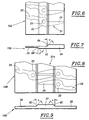
- Figures 6 and 7 show the realization by simply cutting out a series of one-piece members of clamp 21 in. a 10A shape profile.
- Each member 21 forms a half-mesh, or articulation half-zone, 22, provided with an orifice 23 for the passage of the hinge pin of the clamp; on the one hand from this area, a jaw 24 of the forceps; and on the other next to zone 22, a branch nucleus 25.
- the jaw 24 is of the beak type Universal pliers.
- the profile 10A has, in section, three successive parts of increasing thickness: one thick part 24 jaw side, an intermediate part 22 corresponding to the half-mesh, and a thin part 25 corresponding to the branch core.
- the profile On one side (the upper face in Figure 7), the profile is flat on all the parts 22 and 25, and an inclined face 8A along the aforementioned angle ⁇ connects this plane to the plane face parallel of part 24.
- the profile On the other side, the profile is flat on all parts 22 and 24, and one side 5B inclined at an angle ⁇ preferably at least equal to 30 °, for example equal to ⁇ , connects this plane to the face parallel plane of part 25.
- a succession of members 21 are obtained by simple cutting 10A profile, with their main direction substantially perpendicular to the length of the profile.
- the profile 10B has two thin side portions 26 of same thickness, and a thicker central part 27. It is flat on the whole of one of its faces, and on the other side, the part 27 is bordered by two faces 8C inclined at the angle ⁇ .
- the flat underside allows the use of a flat cutting die.
- Same 21A members can be cut in the profile 10C shown in Figures 10 and 11, which has a thin central part 26 and two thick side parts 27. Again, the profile has a completely flat face. In this case, the nozzles 24 are cut in parts 27, and these are the zones 22, 25 which are arranged upside down in the part central 26.
- Figures 12 and 13 illustrate a variant very close to the previous one. However, the area central 26 of profile 10D is wider, which allows to bring together the blanks 21A to each other cut.
- Variant 10F in Figures 16 and 17 does not differs from that in Figures 6 and 7 only in that the lower inclined face 8B is plumb with the upper inclined face 8A. 21B members obtained by cutting this profile 10F therefore differ correspondingly of the members 21.
- Figure 18 shows in perspective a gripper member blank 21A obtained by cutting the profile 10B, 10C, 10D or 10E.
- This draft includes a flat face and, on the other side, a change in thickness progressive 28 at the root of its beak 24.
- Figure 20 represents a 10G profile similar to that of Figures 14 and 15, and Figure 21 shows that from this profile, we can cut either a universal clamp member blank 21A such that that of Figure 18, a draft member 21C of round nose pliers.
- a universal clamp member blank 21A such that that of Figure 18, a draft member 21C of round nose pliers.
- Figure 21 shows that from this profile, we can cut either a universal clamp member blank 21A such that that of Figure 18, a draft member 21C of round nose pliers.
- Global tools making it possible to manufacture a range of pliers is therefore particularly economical.
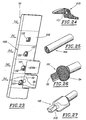
- Management of a fleet of shaped profiles can even be completely deleted if you start from a basic section with simple section in which we realize by forging, cold or hot, a succession of shaped profile sections in each of which there is a cutout, which is made in one step higher.
- This basic profile is forged in several steps ( Figure 23) to form a succession of sections 10H shaped profiles in each of which fits a cutout 33, which is for example that of the blank of the universal clamp 21D in Figure 24.
- Such a method eliminates the phase subsequent machining of the cutter 121.
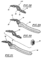
- Figures 28 to 36 illustrate three modes different finishing of a half clamp from a 21F clamp member blank which does not differ from the blank 21A of Figure 18 only by the presence of reliefs 36, such as notches and an orifice, on the core of branch 25.
- the reliefs 36 can be obtained by cut itself.
- This handle can be aluminum, aluminum alloy, or reinforced thermoplastic or thermosetting material or not.
- FIG. 30 we begins by threading by force, or at least with joint waterproof, on the core 25 a ring 40, then the mold for molding the handle on this ring.
- the Finished half clamp is shown in Figure 31.
- the ring 40 is made of a material having a some flexibility or ductility in order to adapt internally to dimensional variations of the nucleus. 25, and externally around the closed mold. This material is for example a plastic material or aluminum.
- the front part of the ring 40 externally enlarged, is visible at the front of the handle and extend it.
- the handle 38 made of plastic, is produced independently by molding and has a cavity 41 which opens at its front end through an opening 42 and laterally through an opening 43 (Figure 34).
- the walls of the cavity 41 have reliefs 44.
- the core 25 of the clamp member is introduced through the opening 42 ( Figure 35), then additional plastic 45 is molded in the cavity 41 to secure the two pieces ( Figure 36).
- the reliefs 36 of the clamp member, and possibly 44 of the handle improve the grip between the two parts after overmolding.
- finishing modes of branch described above with reference to Figures 28 to 36 are also applicable to metallic members obtained by any other suitable process, for example by forging or cutting / stamping flat sheets.
Landscapes
- Engineering & Computer Science (AREA)
- Mechanical Engineering (AREA)
- Forging (AREA)
- Gripping Jigs, Holding Jigs, And Positioning Jigs (AREA)
Claims (14)
- Verfahren zur Herstellung von metallischen Rohteilen (1; 21; 21A; ...; 21F; 29) von Zangenbacken oder Zangen-Griffkernen, aufweisend eine Greifbacke, dadurch gekennzeichnet, dass man die Kontur jedes Rohteils in einem zugehörigen Formprofil-Teilstück (10; 10A; ...; 10I) mit variabler Dicke ausschneidet, dessen Querschnitt mit mindestens einem Schnitt im Längsaufbau des Rohteils korrespondiert.
- Verfahren nach Anspruch 1, dadurch gekennzeichnet, dass das Formprofil-Teilstück (10; 10A; ...; 10I) einstückig und aus einem einzigen Werkstoff ist.
- Verfahren nach Anspruch 1 oder 2, dadurch gekennzeichnet, dass man das Rohteil in einem Profil (10; 10A; ...; 10I) mit konstantem Querschnitt gestaltet.
- Verfahren nach Anspruch 1 oder 2, dadurch gekennzeichnet, dass man von einem Basisprofil (32; 32A) teilt, das einen von den Formprofil-Teilstücken (10H; 10I) unterschiedlichen Querschnitt aufweist, man ausgehend vom Basisprofil durch mindestens einen Schmiedevorgang lokale Formprofil-Teilstücke (10H; 10I) gestaltet und man das Rohteil in jedem der lokalen Teilstücke gestaltet.
- Verfahren nach Anspruch 4, dadurch gekennzeichnet, dass das Basisprofil (32; 32A) ein Band oder eine Stange mit rechteckigem oder polygonalem Querschnitt ist, oder ein Profil mit einem Querschnitt in der Form einer geschlossenen, insbesondere kreisförmigen Krümmung, besonders von einer Rolle abgewickelt, ist.
- Verfahren nach einem der Ansprüche 1 bis 5, dadurch gekennzeichnet, dass die Formprofil-Teilstücke (10B; 10C; 10D; 10E; 10G; 10H; 10I) auf ihrem gesamten Umfang auf einer Seite eine plane Fläche zur Anlage mit einer planen Schnittmatrize aufweisen.
- Verfahren nach einem der Ansprüche 1 bis 6, dadurch gekennzeichnet, dass die Formprofil-Teilstücke (10; 10A; ...; 10I) mindestens eine Oberfläche mit Dickenänderung (8; 8A; 8B; 8C) aufweisen, die, bezogen auf die Senkrechte zur Mittelebene (P) der Teilstücke, insbesondere mit mindestens 30° geneigt ist.
- Verfahren nach einem der Ansprüche 1 bis 7, dadurch gekennzeichnet, dass die Formprofil-Teilstücke (10) mindestens eine Schulter (5) im wesentlichen senkrecht zu ihrer Mittelebene (P) aufweisen, wobei sich die Wurzel der Schulter besonders entlang einer Freistichnut (6) erstreckt.
- Verfahren nach einem der Ansprüche 1 bis 8, dadurch gekennzeichnet, dass der Querschnitt der Formprofil-Teilstücke (10D; 10C; 10D) in der Querrichtung symmetrisch ist, und dadurch, dass man dort durch Ausschneiden Rohteile (21A) gestaltet, deren Kopfteile im Wechsel zueinander angeordnet sind.
- Verfahren nach einem der Ansprüche 1 bis 9, dadurch gekennzeichnet, dass man die Formprofil-Teilstücke (10G) verwendet, um dort mindestens zwei Rohteile mit unterschiedlichen Formen (21A; 21C) auszuschneiden.
- Verfahren zur Herstellung einer Halbzange, dadurch gekennzeichnet, dass man nach einem der Ansprüche 1 bis 10 ein Rohteil (21F) mit einem Zangengriffkern (25) gestaltet und man auf den Kern einen Zangengriff (38) formt.
- Verfahren nach Anspruch 11, dadurch gekennzeichnet, dass die Form des Gussstückes mit einem Adaptier-Ringstück (40) verschlossen wird, das auf dem Griffkern (25) aufgebracht wird.
- Verfahren zur Herstellung einer Halbzange, dadurch gekennzeichnet, dass man nach einem der Ansprüche 1 bis 10, ein Rohteil (21F) eines Zangengriffkerns (25) gestaltet, man den Griffkern (25) in eine Kavität (41) eines vorgeformten Griffes (38) mit Spiel einführt und man den freien verbleibenden Raum in der Kavität mit einem Füllmaterial (45) ausfüllt.
- Verfahren nach Anspruch 13, dadurch gekennzeichnet, dass die Kavität (41) des vorgeformten Griffes (38) nach vorn und zur Seite hin offen ist.
Applications Claiming Priority (3)
| Application Number | Priority Date | Filing Date | Title |
|---|---|---|---|
| FR9612141 | 1996-10-04 | ||
| FR9612141A FR2754196B1 (fr) | 1996-10-04 | 1996-10-04 | Procede de fabrication de pinces |
| PCT/FR1997/001737 WO1998015370A1 (fr) | 1996-10-04 | 1997-10-01 | Procede de fabrication d'ebauches de pieces a pinces |
Publications (2)
| Publication Number | Publication Date |
|---|---|
| EP0935507A1 EP0935507A1 (de) | 1999-08-18 |
| EP0935507B1 true EP0935507B1 (de) | 2002-04-10 |
Family
ID=9496380
Family Applications (1)
| Application Number | Title | Priority Date | Filing Date |
|---|---|---|---|
| EP97943040A Expired - Lifetime EP0935507B1 (de) | 1996-10-04 | 1997-10-01 | Verfahren zum herstellen von zuschnitten für zangenteile |
Country Status (6)
| Country | Link |
|---|---|
| US (1) | US6318212B1 (de) |
| EP (1) | EP0935507B1 (de) |
| AU (1) | AU4465997A (de) |
| DE (1) | DE69711908T2 (de) |
| FR (1) | FR2754196B1 (de) |
| WO (1) | WO1998015370A1 (de) |
Families Citing this family (2)
| Publication number | Priority date | Publication date | Assignee | Title |
|---|---|---|---|---|
| KR20030090049A (ko) * | 2002-05-21 | 2003-11-28 | 현대자동차주식회사 | 자동차용 알루미늄 로워암의 제조 방법 |
| TWI650064B (zh) * | 2018-02-14 | 2019-02-11 | 慶璉實業股份有限公司 | 樹剪刀座製造方法 |
Family Cites Families (13)
| Publication number | Priority date | Publication date | Assignee | Title |
|---|---|---|---|---|
| GB213812A (en) * | 1923-06-19 | 1924-04-10 | Gustav Klauke | Tool insulator specially for the handles of pliers and the like |
| FR1054724A (fr) * | 1952-04-21 | 1954-02-12 | Procédé de fabrication de récipients de mesure pour liquides | |
| US2825248A (en) * | 1955-11-28 | 1958-03-04 | Fred E Ahlbin | Scissors and method of making |
| US3114973A (en) * | 1962-04-25 | 1963-12-24 | Ekco Products Company | Knife assembly |
| FI51063C (fi) * | 1975-06-11 | 1976-10-11 | Fiskars Ab Oy | Saksien ja sentapaisten muovikädensijojen kiinnityssovitelma. |
| JPS6076235A (ja) * | 1983-09-14 | 1985-04-30 | Riken Kaki Kogyo Kk | プライヤの製造方法 |
| CA1306959C (en) * | 1987-11-02 | 1992-09-01 | James H. Sheets | Brake shoe rib and a method of making same |
| DE9112630U1 (de) * | 1991-10-10 | 1991-12-12 | Fa. Hans Plier, 5630 Remscheid | Zangen-Handgriff |
| US5244141A (en) * | 1992-05-15 | 1993-09-14 | Doolittle Milton A | Method of manufacturing multi-characteristic small thin flat metallic parts |
| US5253557A (en) * | 1992-11-12 | 1993-10-19 | The Triangle Tool Group, Inc. A Subsidiary Of The Triangle Corporation | Ergonomic handle construction for hand-held tools |
| US5528834A (en) * | 1994-01-12 | 1996-06-25 | Buck Knives, Inc. | Fixed-blade knife for rugged service and its manufacture |
| US5551323A (en) * | 1995-03-22 | 1996-09-03 | Beere Precision Medical Instruments, Inc. | Screwdriver handle |
| US5809853A (en) * | 1996-10-23 | 1998-09-22 | Hudson; Robert V. | Protective grip for pliers-type tool |
-
1996
- 1996-10-04 FR FR9612141A patent/FR2754196B1/fr not_active Expired - Fee Related
-
1997
- 1997-10-01 WO PCT/FR1997/001737 patent/WO1998015370A1/fr not_active Ceased
- 1997-10-01 AU AU44659/97A patent/AU4465997A/en not_active Abandoned
- 1997-10-01 DE DE69711908T patent/DE69711908T2/de not_active Expired - Lifetime
- 1997-10-01 US US09/269,884 patent/US6318212B1/en not_active Expired - Fee Related
- 1997-10-01 EP EP97943040A patent/EP0935507B1/de not_active Expired - Lifetime
Also Published As
| Publication number | Publication date |
|---|---|
| DE69711908T2 (de) | 2002-11-07 |
| WO1998015370A1 (fr) | 1998-04-16 |
| FR2754196A1 (fr) | 1998-04-10 |
| AU4465997A (en) | 1998-05-05 |
| EP0935507A1 (de) | 1999-08-18 |
| FR2754196B1 (fr) | 1998-12-18 |
| US6318212B1 (en) | 2001-11-20 |
| DE69711908D1 (de) | 2002-05-16 |
Similar Documents
| Publication | Publication Date | Title |
|---|---|---|
| FR2482883A1 (fr) | Procede de forgeage de precision a matrices closes | |
| EP0792722A1 (de) | Schneidewerkzeug vom Typ-Bolzenschneider | |
| EP2864067B1 (de) | Rohrkerbungsverfahren und zugehörige kerbungsmaschine | |
| CA2208435C (fr) | Structure metallique creuse monobloc et dissymetrique telle qu'un bord de fuite d'un bec d'attaque d'une voilure d'aeronef et son procede de fabrication | |
| EP1930146A1 (de) | Speiche aus Verbundmaterial für ein Speichenrad | |
| EP3286028B1 (de) | Extrudierte verstärkungsträger mit präparierter verformung | |
| FR2483811A1 (fr) | Machoire de serrage de mandrin pour outil de pose de rivets par tirage, et procede de realisation de ladite machoire | |
| EP0635337A2 (de) | Verfahren zur Herstellung eines Werkzeuggriffes und Werkzeug mit einem nach diesem Verfahren hergestellten Griff | |
| EP0935507A1 (de) | Verfahren zum herstellen von zuschnitten für zangenteile | |
| EP0727289B1 (de) | Schraubendreherrohling, Schraubendreher und Satz von Schraubendrehern, hergestellt aus einem solchen Rohling und Verfahren zu deren Herstellung | |
| FR2754204A1 (fr) | Procede de fabrication d'une branche d'outil, et gamme de pinces correspondante | |
| FR2689968A1 (fr) | Lame d'escrime. | |
| FR2552830A1 (fr) | Rivet aveugle a tete secondaire de grandes dimensions | |
| FR2983120A1 (fr) | Procede de fabrication d'une roue comportant au moins une cuvette peinte | |
| EP0868266B1 (de) | Verfahren zur herstellung eines werkzeughandgriffes und dazugehöriges werkzeug | |
| FR2586606A1 (fr) | Procede de fabrication d'ebauche d'ensemble de lame de couteau et couteau obtenu a partir d'une telle ebauche | |
| EP1714573A1 (de) | Metallischer Zusatz für Sportschuh | |
| FR2642268A1 (fr) | Procede de fabrication de moules de fromagerie micro-perfores, et moule obtenu par ce procede | |
| BE1032890A1 (fr) | Dispositif de cintrage d'une pièce allongée | |
| FR3026326A1 (fr) | Corps metallique pour article de table, procede de realisation d'un motif sur un corps metallique et methode de fabrication d'un article de table | |
| FR3068904A1 (fr) | Procede de fabrication d'un couteau a lame forgee et couteau a lame forgee | |
| EP4414181A1 (de) | Schlagwerkzeug mit einem stampfer und zugehöriges stampfverfahren | |
| US341415A (en) | James d | |
| FR2702400A1 (fr) | Perfectionnement pour outillage destiné à être utilisé pour le filage par choc de pièces en alliage léger. | |
| CH720488A2 (fr) | Outil de frappe formant une étampe, et procédé d'étampage associé |
Legal Events
| Date | Code | Title | Description |
|---|---|---|---|
| PUAI | Public reference made under article 153(3) epc to a published international application that has entered the european phase |
Free format text: ORIGINAL CODE: 0009012 |
|
| 17P | Request for examination filed |
Effective date: 19990406 |
|
| AK | Designated contracting states |
Kind code of ref document: A1 Designated state(s): DE GB IT NL SE |
|
| 17Q | First examination report despatched |
Effective date: 19990831 |
|
| GRAG | Despatch of communication of intention to grant |
Free format text: ORIGINAL CODE: EPIDOS AGRA |
|
| GRAG | Despatch of communication of intention to grant |
Free format text: ORIGINAL CODE: EPIDOS AGRA |
|
| GRAH | Despatch of communication of intention to grant a patent |
Free format text: ORIGINAL CODE: EPIDOS IGRA |
|
| REG | Reference to a national code |
Ref country code: GB Ref legal event code: IF02 |
|
| GRAH | Despatch of communication of intention to grant a patent |
Free format text: ORIGINAL CODE: EPIDOS IGRA |
|
| GRAA | (expected) grant |
Free format text: ORIGINAL CODE: 0009210 |
|
| AK | Designated contracting states |
Kind code of ref document: B1 Designated state(s): DE GB IT NL SE |
|
| PG25 | Lapsed in a contracting state [announced via postgrant information from national office to epo] |
Ref country code: NL Free format text: LAPSE BECAUSE OF FAILURE TO SUBMIT A TRANSLATION OF THE DESCRIPTION OR TO PAY THE FEE WITHIN THE PRESCRIBED TIME-LIMIT Effective date: 20020410 |
|
| REF | Corresponds to: |
Ref document number: 69711908 Country of ref document: DE Date of ref document: 20020516 |
|
| PG25 | Lapsed in a contracting state [announced via postgrant information from national office to epo] |
Ref country code: SE Free format text: LAPSE BECAUSE OF FAILURE TO SUBMIT A TRANSLATION OF THE DESCRIPTION OR TO PAY THE FEE WITHIN THE PRESCRIBED TIME-LIMIT Effective date: 20020710 |
|
| GBT | Gb: translation of ep patent filed (gb section 77(6)(a)/1977) |
Effective date: 20020712 |
|
| NLV1 | Nl: lapsed or annulled due to failure to fulfill the requirements of art. 29p and 29m of the patents act | ||
| PLBE | No opposition filed within time limit |
Free format text: ORIGINAL CODE: 0009261 |
|
| STAA | Information on the status of an ep patent application or granted ep patent |
Free format text: STATUS: NO OPPOSITION FILED WITHIN TIME LIMIT |
|
| 26N | No opposition filed |
Effective date: 20030113 |
|
| PGFP | Annual fee paid to national office [announced via postgrant information from national office to epo] |
Ref country code: GB Payment date: 20100923 Year of fee payment: 14 |
|
| PGFP | Annual fee paid to national office [announced via postgrant information from national office to epo] |
Ref country code: DE Payment date: 20101012 Year of fee payment: 14 |
|
| PGFP | Annual fee paid to national office [announced via postgrant information from national office to epo] |
Ref country code: IT Payment date: 20101027 Year of fee payment: 14 |
|
| REG | Reference to a national code |
Ref country code: GB Ref legal event code: 732E Free format text: REGISTERED BETWEEN 20130404 AND 20130410 |
|
| GBPC | Gb: european patent ceased through non-payment of renewal fee |
Effective date: 20121001 |
|
| PG25 | Lapsed in a contracting state [announced via postgrant information from national office to epo] |
Ref country code: GB Free format text: LAPSE BECAUSE OF NON-PAYMENT OF DUE FEES Effective date: 20121001 Ref country code: DE Free format text: LAPSE BECAUSE OF NON-PAYMENT OF DUE FEES Effective date: 20130501 |
|
| REG | Reference to a national code |
Ref country code: DE Ref legal event code: R119 Ref document number: 69711908 Country of ref document: DE Effective date: 20130501 |
|
| PG25 | Lapsed in a contracting state [announced via postgrant information from national office to epo] |
Ref country code: IT Free format text: LAPSE BECAUSE OF NON-PAYMENT OF DUE FEES Effective date: 20121001 |