EP0935510B1 - Machine-outil pour l'usinage par enlevement de copeaux de grosses pieces - Google Patents
Machine-outil pour l'usinage par enlevement de copeaux de grosses pieces Download PDFInfo
- Publication number
- EP0935510B1 EP0935510B1 EP97948856A EP97948856A EP0935510B1 EP 0935510 B1 EP0935510 B1 EP 0935510B1 EP 97948856 A EP97948856 A EP 97948856A EP 97948856 A EP97948856 A EP 97948856A EP 0935510 B1 EP0935510 B1 EP 0935510B1
- Authority
- EP
- European Patent Office
- Prior art keywords
- machine tool
- column
- supporting structure
- machining
- machine
- Prior art date
- Legal status (The legal status is an assumption and is not a legal conclusion. Google has not performed a legal analysis and makes no representation as to the accuracy of the status listed.)
- Expired - Lifetime
Links
- 238000003754 machining Methods 0.000 title claims description 23
- 229910000838 Al alloy Inorganic materials 0.000 claims description 2
- 229910052751 metal Inorganic materials 0.000 claims 1
- 239000002184 metal Substances 0.000 claims 1
- 230000001133 acceleration Effects 0.000 description 5
- 238000010276 construction Methods 0.000 description 2
- 239000002826 coolant Substances 0.000 description 2
- 238000000034 method Methods 0.000 description 2
- 238000001816 cooling Methods 0.000 description 1
- 230000005484 gravity Effects 0.000 description 1
Images
Classifications
-
- B—PERFORMING OPERATIONS; TRANSPORTING
- B23—MACHINE TOOLS; METAL-WORKING NOT OTHERWISE PROVIDED FOR
- B23Q—DETAILS, COMPONENTS, OR ACCESSORIES FOR MACHINE TOOLS, e.g. ARRANGEMENTS FOR COPYING OR CONTROLLING; MACHINE TOOLS IN GENERAL CHARACTERISED BY THE CONSTRUCTION OF PARTICULAR DETAILS OR COMPONENTS; COMBINATIONS OR ASSOCIATIONS OF METAL-WORKING MACHINES, NOT DIRECTED TO A PARTICULAR RESULT
- B23Q1/00—Members which are comprised in the general build-up of a form of machine, particularly relatively large fixed members
- B23Q1/01—Frames, beds, pillars or like members; Arrangement of ways
- B23Q1/015—Frames, beds, pillars
-
- B—PERFORMING OPERATIONS; TRANSPORTING
- B23—MACHINE TOOLS; METAL-WORKING NOT OTHERWISE PROVIDED FOR
- B23Q—DETAILS, COMPONENTS, OR ACCESSORIES FOR MACHINE TOOLS, e.g. ARRANGEMENTS FOR COPYING OR CONTROLLING; MACHINE TOOLS IN GENERAL CHARACTERISED BY THE CONSTRUCTION OF PARTICULAR DETAILS OR COMPONENTS; COMBINATIONS OR ASSOCIATIONS OF METAL-WORKING MACHINES, NOT DIRECTED TO A PARTICULAR RESULT
- B23Q1/00—Members which are comprised in the general build-up of a form of machine, particularly relatively large fixed members
- B23Q1/25—Movable or adjustable work or tool supports
- B23Q1/44—Movable or adjustable work or tool supports using particular mechanisms
- B23Q1/56—Movable or adjustable work or tool supports using particular mechanisms with sliding pairs only, the sliding pairs being the first two elements of the mechanism
-
- B—PERFORMING OPERATIONS; TRANSPORTING
- B23—MACHINE TOOLS; METAL-WORKING NOT OTHERWISE PROVIDED FOR
- B23Q—DETAILS, COMPONENTS, OR ACCESSORIES FOR MACHINE TOOLS, e.g. ARRANGEMENTS FOR COPYING OR CONTROLLING; MACHINE TOOLS IN GENERAL CHARACTERISED BY THE CONSTRUCTION OF PARTICULAR DETAILS OR COMPONENTS; COMBINATIONS OR ASSOCIATIONS OF METAL-WORKING MACHINES, NOT DIRECTED TO A PARTICULAR RESULT
- B23Q1/00—Members which are comprised in the general build-up of a form of machine, particularly relatively large fixed members
- B23Q1/70—Stationary or movable members for carrying working-spindles for attachment of tools or work
Definitions
- the invention relates to a machine tool for cutting Machining large components, especially of Airplane integral components made of aluminum alloys with large Machining volume.
- These components can have lengths of 2 to 30 m, widths of 2 to 4 m and heights up to 0.5 m and are achieved with a degree of machining processed by over 90%. This is a The greatest possible machining performance of the machining tools required to do this at great speed as well large accelerations and decelerations should be traversable.
- the state of the art in these machine tools is to arrange a portal machine tool over a fixed table arranged on a machine bed for receiving pallets with the workpiece, the parallel, vertical stands of which can be moved on guides on both sides of the machine bed and up to three independently on a crossbar carry transversely movable processing tools.
- the spindle speed of the machining tools is 10,000 to 30,000 min -1 , and the stands with the crossbeams, the tools and their drives are accelerated with 0.2 to 0.5 g during the process. For this reason, the traversing drive for the stands interacts simultaneously with the guides of each stand so that the moving masses of the portal are accelerated and braked evenly and synchronously.
- a machine tool is to be cut Machining large components known, one on a foundation or machine bed on stands that can be moved on guides which immediately has at least one movable in several axes Machining tool is arranged with its drives, wherein a vertical concrete support structure with guides for the upper end of the stand is arranged behind the stand and at least one with the guides of the machine bed and the Support structure synchronously interacting traversing drive for the Stand is provided.
- the processing tool is therefore of the Support structure facing away, so that the machining of a workpiece takes place on the side of the stand facing away from the support structure.
- the problem underlying the invention is a machine tool for machining large components so that with simple construction and reduction of the masses to be moved precise guidance for large accelerations and decelerations is achieved, thereby cutting performance and the To increase machining accuracy. In addition, at Machine tool chip removal can be improved.
- a Machine tool with at least one on a machine bed Guides movable stand on which at least one immediately Machining tool movable in several axes with its Is arranged, a support structure made of concrete with a drive Guide for the top of the stand, at least one with the Guides of the machine bed and the support structure synchronously interacting travel drive for the stand proposed that according to the invention the side facing the stand Support structure as a support for a vertically arranged workpiece is formed and that the guides of the stand are adjustable are.
- the foundation can also preferably be used or the machine bed made of concrete and the Guides can be adjustably attached.
- the vertical arrangement of the workpiece is a much easier chip removal reached because the chips fall off the tool and themselves easily using the anyway to cool the Machining tools used coolant from the workpiece let it rinse off.
- two electrical, controlled synchronously running travel drives are provided, the each with the guide on the machine bed and the guide on the Interact support structure.
- a guide for the stand on the The upper edge of the support structure can be arranged and the Stand facing side of the support structure for recordings have interchangeable pallets carrying a workpiece so that another while machining a workpiece Prepare the workpiece on a pallet and quickly face it finished workpiece can be replaced.
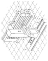
- the one Machine tool with one arranged on a support structure shows vertical pallet for a workpiece to be machined.
- the stand 14 can be longitudinal drive the bed 13 on the guides 16.
- Parallel to the guide 16 is a support structure 17 in the form of a vertical concrete wall arranged by regularly arranged buttresses 18th is additionally supported.
- On the top of the support structure 17 there is a guide 19 which is parallel to the guides 16 runs.
- the stand 14 has a boom 15 which the Guide 19 overlaps.
- One in a vertical direction movable carriage 20 is a horizontal support 21 arranged of a machining tool 22 with its drive wearing.
- the machining tool 22 with its drive is in one Fork receptacle 23 arranged on the carrier 21 and can therefore be move multi-axis.
- the guides 16 and the support structure 17 with the guide 19th can be formed very long to work pieces with a length of 2 to 30 m, a width of 2 to 4 m and a thickness of up to 0.5 m to be able to edit. Due to the vertical arrangement of the Workpiece removal is much easier because the chips already fall down by gravity and turn out by machining cavities created by means of cooling of the machining tool 22 required coolant easily let it rinse out.
- Several stands 14 can be on the Arrange the guide 16 to hold particularly long workpieces on several To be able to edit positions at the same time.
- the guides 16, 19 and the receptacles 24 for pallets 25 are adjustable to any inaccuracies in the surface of the To be able to compensate for the support structure 17 and the machine bed 13.
Landscapes
- Engineering & Computer Science (AREA)
- Mechanical Engineering (AREA)
- Machine Tool Units (AREA)
Claims (5)
- Machine-outil pour usinage par enlèvement de copeaux de grands composants, en particulier de composants intégrés d'avions, en alliages d'aluminium, avec un grand volume de copeaux enlevés, comportant au moins un montant (14), qui est déplaçable sur des guides (16) sur un banc de machine (13) et sur lequel est disposé directement au moins un outil d'usinage (22), déplaçable suivant plusieurs axes, avec ses dispositifs d'entraínement, comportant une structure de soutien (17) en béton avec un guide (19) pour l'extrémité supérieure du montant (14), et comportant au moins un dispositif d'entraínement en translation pour le montant (14), qui coopère de manière synchrone avec les guides (16, 19) du banc de machine (13) et avec la structure de soutien (17), caractérisée en ce que le côté de la structure de soutien (17) tourné vers le montant (14), est conformé en montant pour une pièce à usiner disposée verticalement, et en ce que les guides (16, 19) peuvent être ajustés.
- Machine-outil selon la revendication 1, caractérisée par deux dispositifs d'entraínement en translation électriques, commandés de manière synchrone, pour le montant (14).
- Machine-outil selon la revendication 1 ou 2, caractérisée en ce que le banc de machine (13) est réalisé en béton.
- Machine-outil selon la revendication 1 ou 2, caractérisée en ce que les guides (16) sont fixés au banc de machine (13) de manière à pouvoir être ajustés.
- Machine-outil selon la revendication 1, caractérisée ce que le guide (19) du montant (14) est disposé sur le bord supérieur de la structure de soutien (17) et le côté de la structure de soutien (17), tourné vers les montant (14), présente des logements (24) pour des palettes (25) échangeables, qui portent une pièce à usiner.
Applications Claiming Priority (3)
| Application Number | Priority Date | Filing Date | Title |
|---|---|---|---|
| DE19645324 | 1996-11-04 | ||
| DE19645324A DE19645324A1 (de) | 1996-11-04 | 1996-11-04 | Werkzeugmaschine zur spanenden Bearbeitung großer Bauteile |
| PCT/EP1997/006036 WO1998019819A1 (fr) | 1996-11-04 | 1997-11-03 | Machine-outil pour l'usinage par enlevement de copeaux de grosses pieces |
Publications (2)
| Publication Number | Publication Date |
|---|---|
| EP0935510A1 EP0935510A1 (fr) | 1999-08-18 |
| EP0935510B1 true EP0935510B1 (fr) | 2001-09-12 |
Family
ID=7810554
Family Applications (1)
| Application Number | Title | Priority Date | Filing Date |
|---|---|---|---|
| EP97948856A Expired - Lifetime EP0935510B1 (fr) | 1996-11-04 | 1997-11-03 | Machine-outil pour l'usinage par enlevement de copeaux de grosses pieces |
Country Status (3)
| Country | Link |
|---|---|
| EP (1) | EP0935510B1 (fr) |
| DE (2) | DE19645324A1 (fr) |
| WO (1) | WO1998019819A1 (fr) |
Cited By (1)
| Publication number | Priority date | Publication date | Assignee | Title |
|---|---|---|---|---|
| WO2025257621A1 (fr) * | 2024-06-14 | 2025-12-18 | Innse-Berardi S.P.A. | Machine de fraisage pour l'usinage de pièces d'aluminium |
Families Citing this family (15)
| Publication number | Priority date | Publication date | Assignee | Title |
|---|---|---|---|---|
| DE29801236U1 (de) * | 1998-01-27 | 1998-03-19 | DS Technologie Werkzeugmaschinen GmbH, 41236 Mönchengladbach | Werkzeugmaschine zur spanenden Bearbeitung großer Bauteile |
| DE19857013C2 (de) | 1998-12-09 | 2001-09-06 | Schwaebische Werkzeugmaschinen | Werkzeugmaschine mit horizontaler Arbeitsspindel |
| DE19857012C3 (de) | 1998-12-09 | 2002-10-24 | Schwaebische Werkzeugmaschinen | Werkzeugmaschine mit horizontal angeordneter Arbeitsspindel |
| DE10050141C2 (de) | 2000-10-11 | 2002-11-14 | Ds Technologie Werkzeugmaschb | Ständerwerkzeugmaschine |
| DE10061934B4 (de) * | 2000-12-13 | 2005-06-16 | Deckel Maho Pfronten Gmbh | Werkzeugmaschine zur spanenden Werkstückbearbeitung |
| DE10252824A1 (de) | 2002-11-13 | 2004-06-03 | Deckel Maho Pfronten Gmbh | Werkzeugmaschine |
| DE102004014912B4 (de) * | 2003-03-26 | 2011-12-22 | Mauser-Werke Oberndorf Maschinenbau Gmbh | Werkzeugmaschine zur Schwerzerspanung |
| DE602004012164T2 (de) * | 2004-04-07 | 2009-03-12 | Hpt Sinergy S.R.L. | Horizontale fräsbohrmaschine mit mobiler säule |
| EP2260973B1 (fr) * | 2008-03-14 | 2012-12-26 | Makino Milling Machine Co. Ltd. | Machine-outil |
| US7534078B1 (en) * | 2008-04-22 | 2009-05-19 | Cincinnati Machine, Llc | Consistent rigidity construction arrangement for a machine tool |
| US8662802B2 (en) | 2011-03-04 | 2014-03-04 | Fives Machining Systems, Inc. | High rigidity moving column horizontal machine tool |
| DE102013013276A1 (de) | 2013-08-08 | 2015-02-12 | Liebherr-Verzahntechnik Gmbh | Werkzeugmaschine und Verfahren zur spanenden Bearbeitung von Werkstücken mit mindestens zwei separaten Bearbeitungseinheiten |
| JP6389618B2 (ja) * | 2014-02-24 | 2018-09-12 | Dmg森精機株式会社 | 工作機械の移動体案内機構 |
| CN110039095A (zh) * | 2019-04-08 | 2019-07-23 | 科德数控股份有限公司 | 一种卧式五轴翻板加工中心 |
| US20230294225A1 (en) * | 2020-08-05 | 2023-09-21 | Fidia S.P.A. | Machine tool with two independent carriages |
Family Cites Families (7)
| Publication number | Priority date | Publication date | Assignee | Title |
|---|---|---|---|---|
| US1422140A (en) * | 1920-08-06 | 1922-07-11 | Niles Bementpond Co | Car-wheel-boring machine |
| US3800636A (en) * | 1972-10-13 | 1974-04-02 | F Zagar | Concrete frame machines |
| DE2405163A1 (de) * | 1974-02-04 | 1975-08-21 | Heyligenstaedt & Co | Portalfraesmaschine mit einem beweglichen portal |
| DD240351A1 (de) * | 1985-08-19 | 1986-10-29 | Werkzeugmasch Okt Veb | Industrieroboter fuer die handhabung von werkstuecken und werkzeugen |
| FR2652291B1 (fr) * | 1989-09-27 | 1992-01-10 | Helis | Machine d'usinage a montant mobile et a broche horizontale. |
| DE9218186U1 (de) * | 1992-04-25 | 1993-08-19 | Ehing, Günther, 71069 Sindelfingen | Abstützbolzen |
| IT1268482B1 (it) * | 1993-02-12 | 1997-03-04 | Jobs Spa | Macchina utensile automatica a struttura aperta, trasformabile in macchina utensile a struttura chiusa quale una macchina a portale. |
-
1996
- 1996-11-04 DE DE19645324A patent/DE19645324A1/de not_active Withdrawn
-
1997
- 1997-11-03 DE DE59704613T patent/DE59704613D1/de not_active Expired - Fee Related
- 1997-11-03 EP EP97948856A patent/EP0935510B1/fr not_active Expired - Lifetime
- 1997-11-03 WO PCT/EP1997/006036 patent/WO1998019819A1/fr not_active Ceased
Cited By (1)
| Publication number | Priority date | Publication date | Assignee | Title |
|---|---|---|---|---|
| WO2025257621A1 (fr) * | 2024-06-14 | 2025-12-18 | Innse-Berardi S.P.A. | Machine de fraisage pour l'usinage de pièces d'aluminium |
Also Published As
| Publication number | Publication date |
|---|---|
| WO1998019819A1 (fr) | 1998-05-14 |
| DE59704613D1 (de) | 2001-10-18 |
| EP0935510A1 (fr) | 1999-08-18 |
| DE19645324A1 (de) | 1998-05-14 |
Similar Documents
| Publication | Publication Date | Title |
|---|---|---|
| EP0935510B1 (fr) | Machine-outil pour l'usinage par enlevement de copeaux de grosses pieces | |
| EP0512126B1 (fr) | Dispositif pour la manutention de produits en feuilles | |
| DE19503482C2 (de) | Werkzeugmaschine mit einem Ständer, an dem zwei Spindelstöcke unabhängig voneinander verfahrbar sind | |
| DE3035451C2 (fr) | ||
| EP2623255B1 (fr) | Machine-outil universelle avec espace de collecte des copeaux | |
| DE10050141C2 (de) | Ständerwerkzeugmaschine | |
| DE69700651T2 (de) | Werkzeugmaschinenstruktur für hochgeschwindigkeitsspindel | |
| EP1186371A1 (fr) | Fraiseuse du type à portique | |
| EP1291122A2 (fr) | Centre d'usinage pour fraisage et forage | |
| EP1216779A1 (fr) | Machine-outil, en particulier machine pour usinage par électroérosion, et ensemble de construction modulaire | |
| WO2013071984A1 (fr) | Machine-outil | |
| DE873817T1 (de) | Werkzeugmaschine zum Bearbeiten von langen Werkstücken | |
| EP1413395A1 (fr) | Machine-outil | |
| DE602004001733T2 (de) | Horizontal-Bearbeitungszentrum | |
| DE4015570A1 (de) | Werkzeugmaschine, insbesondere vertikal-schleifmaschine und verfahren zum bearbeiten von werkstuecken mit dieser maschine | |
| EP0928235B1 (fr) | Machine-outil pour usinage par enlevement de copeaux, presentant une broche de travail horizontale | |
| DE4229423C2 (de) | Drehmaschine | |
| EP1186372B1 (fr) | Fraiseuse à portique | |
| EP1574273A1 (fr) | Tour | |
| DE19855197A1 (de) | Programmgesteuerte Schleifmaschine | |
| DE69225021T2 (de) | Spanabhebende Bearbeitungseinheit | |
| DE29805195U1 (de) | Maschine zum Bearbeiten von plattenartigen Werkstücken, insbesondere von Blechen | |
| DE29801236U1 (de) | Werkzeugmaschine zur spanenden Bearbeitung großer Bauteile | |
| DE2653928A1 (de) | Bearbeitungszentrum | |
| DE29623372U1 (de) | Werkzeugmaschine zur spanenden Bearbeitung großer Bauteile |
Legal Events
| Date | Code | Title | Description |
|---|---|---|---|
| PUAI | Public reference made under article 153(3) epc to a published international application that has entered the european phase |
Free format text: ORIGINAL CODE: 0009012 |
|
| 17P | Request for examination filed |
Effective date: 19990601 |
|
| AK | Designated contracting states |
Kind code of ref document: A1 Designated state(s): DE FR GB |
|
| 17Q | First examination report despatched |
Effective date: 19990913 |
|
| 111Z | Information provided on other rights and legal means of execution |
Free format text: 20001013 DE FR GB |
|
| GRAG | Despatch of communication of intention to grant |
Free format text: ORIGINAL CODE: EPIDOS AGRA |
|
| GRAG | Despatch of communication of intention to grant |
Free format text: ORIGINAL CODE: EPIDOS AGRA |
|
| GRAH | Despatch of communication of intention to grant a patent |
Free format text: ORIGINAL CODE: EPIDOS IGRA |
|
| GRAH | Despatch of communication of intention to grant a patent |
Free format text: ORIGINAL CODE: EPIDOS IGRA |
|
| GRAA | (expected) grant |
Free format text: ORIGINAL CODE: 0009210 |
|
| AK | Designated contracting states |
Kind code of ref document: B1 Designated state(s): DE FR GB |
|
| REF | Corresponds to: |
Ref document number: 59704613 Country of ref document: DE Date of ref document: 20011018 |
|
| REG | Reference to a national code |
Ref country code: GB Ref legal event code: IF02 |
|
| GBT | Gb: translation of ep patent filed (gb section 77(6)(a)/1977) |
Effective date: 20011201 |
|
| ET | Fr: translation filed | ||
| PLBE | No opposition filed within time limit |
Free format text: ORIGINAL CODE: 0009261 |
|
| STAA | Information on the status of an ep patent application or granted ep patent |
Free format text: STATUS: NO OPPOSITION FILED WITHIN TIME LIMIT |
|
| 26N | No opposition filed | ||
| REG | Reference to a national code |
Ref country code: FR Ref legal event code: CD |
|
| PGFP | Annual fee paid to national office [announced via postgrant information from national office to epo] |
Ref country code: DE Payment date: 20081127 Year of fee payment: 12 |
|
| PGFP | Annual fee paid to national office [announced via postgrant information from national office to epo] |
Ref country code: FR Payment date: 20081118 Year of fee payment: 12 |
|
| PGFP | Annual fee paid to national office [announced via postgrant information from national office to epo] |
Ref country code: GB Payment date: 20081121 Year of fee payment: 12 |
|
| GBPC | Gb: european patent ceased through non-payment of renewal fee |
Effective date: 20091103 |
|
| REG | Reference to a national code |
Ref country code: FR Ref legal event code: ST Effective date: 20100730 |
|
| PG25 | Lapsed in a contracting state [announced via postgrant information from national office to epo] |
Ref country code: FR Free format text: LAPSE BECAUSE OF NON-PAYMENT OF DUE FEES Effective date: 20091130 |
|
| PG25 | Lapsed in a contracting state [announced via postgrant information from national office to epo] |
Ref country code: DE Free format text: LAPSE BECAUSE OF NON-PAYMENT OF DUE FEES Effective date: 20100601 |
|
| PG25 | Lapsed in a contracting state [announced via postgrant information from national office to epo] |
Ref country code: GB Free format text: LAPSE BECAUSE OF NON-PAYMENT OF DUE FEES Effective date: 20091103 |