EP0935543B1 - Dispositif avec un cylindre de fermeture et un commutateur de fonctions electriques diverses, notamment contacteur d'allumage pour vehicules a moteur - Google Patents
Dispositif avec un cylindre de fermeture et un commutateur de fonctions electriques diverses, notamment contacteur d'allumage pour vehicules a moteur Download PDFInfo
- Publication number
- EP0935543B1 EP0935543B1 EP97909241A EP97909241A EP0935543B1 EP 0935543 B1 EP0935543 B1 EP 0935543B1 EP 97909241 A EP97909241 A EP 97909241A EP 97909241 A EP97909241 A EP 97909241A EP 0935543 B1 EP0935543 B1 EP 0935543B1
- Authority
- EP
- European Patent Office
- Prior art keywords
- cylinder
- key
- cylinder core
- evaluator
- locking
- Prior art date
- Legal status (The legal status is an assumption and is not a legal conclusion. Google has not performed a legal analysis and makes no representation as to the accuracy of the status listed.)
- Expired - Lifetime
Links
Images


Classifications
-
- E—FIXED CONSTRUCTIONS
- E05—LOCKS; KEYS; WINDOW OR DOOR FITTINGS; SAFES
- E05B—LOCKS; ACCESSORIES THEREFOR; HANDCUFFS
- E05B49/00—Electric permutation locks; Circuits therefor ; Mechanical aspects of electronic locks; Mechanical keys therefor
-
- B—PERFORMING OPERATIONS; TRANSPORTING
- B60—VEHICLES IN GENERAL
- B60R—VEHICLES, VEHICLE FITTINGS, OR VEHICLE PARTS, NOT OTHERWISE PROVIDED FOR
- B60R25/00—Fittings or systems for preventing or indicating unauthorised use or theft of vehicles
- B60R25/20—Means to switch the anti-theft system on or off
- B60R25/2063—Ignition switch geometry
-
- B—PERFORMING OPERATIONS; TRANSPORTING
- B60—VEHICLES IN GENERAL
- B60R—VEHICLES, VEHICLE FITTINGS, OR VEHICLE PARTS, NOT OTHERWISE PROVIDED FOR
- B60R25/00—Fittings or systems for preventing or indicating unauthorised use or theft of vehicles
- B60R25/01—Fittings or systems for preventing or indicating unauthorised use or theft of vehicles operating on vehicle systems or fittings, e.g. on doors, seats or windscreens
- B60R25/04—Fittings or systems for preventing or indicating unauthorised use or theft of vehicles operating on vehicle systems or fittings, e.g. on doors, seats or windscreens operating on the propulsion system, e.g. engine or drive motor
-
- E—FIXED CONSTRUCTIONS
- E05—LOCKS; KEYS; WINDOW OR DOOR FITTINGS; SAFES
- E05B—LOCKS; ACCESSORIES THEREFOR; HANDCUFFS
- E05B17/00—Accessories in connection with locks
- E05B17/22—Means for operating or controlling lock or fastening device accessories, i.e. other than the fastening members, e.g. switches, indicators
-
- G—PHYSICS
- G07—CHECKING-DEVICES
- G07C—TIME OR ATTENDANCE REGISTERS; REGISTERING OR INDICATING THE WORKING OF MACHINES; GENERATING RANDOM NUMBERS; VOTING OR LOTTERY APPARATUS; ARRANGEMENTS, SYSTEMS OR APPARATUS FOR CHECKING NOT PROVIDED FOR ELSEWHERE
- G07C9/00—Individual registration on entry or exit
- G07C9/00174—Electronically operated locks; Circuits therefor; Nonmechanical keys therefor, e.g. passive or active electrical keys or other data carriers without mechanical keys
- G07C9/00658—Electronically operated locks; Circuits therefor; Nonmechanical keys therefor, e.g. passive or active electrical keys or other data carriers without mechanical keys operated by passive electrical keys
- G07C9/00722—Electronically operated locks; Circuits therefor; Nonmechanical keys therefor, e.g. passive or active electrical keys or other data carriers without mechanical keys operated by passive electrical keys with magnetic components, e.g. magnets, magnetic strips, metallic inserts
- G07C9/00738—Electronically operated locks; Circuits therefor; Nonmechanical keys therefor, e.g. passive or active electrical keys or other data carriers without mechanical keys operated by passive electrical keys with magnetic components, e.g. magnets, magnetic strips, metallic inserts sensed by Hall effect devices
Definitions
- the invention is directed to a device of the type specified in the preamble of claim 1.
- a generic device is known from US-A-5 186 031.
- the locking cylinder consists of a stationary cylinder housing and a cylinder core that is rotatably mounted in it.
- the key can only be inserted and removed from the key channel in a specific starting rotary position of the cylinder core.
- the cylinder core can be brought into certain defined rotational positions, which will be referred to as "working positions" for short. In these working positions, certain electrical functions in the motor vehicle or another useful object are activated or deactivated via the switching device.
- ignition starter switch When used in motor vehicles, such a device serves as so-called "ignition starter switch".
- the switching device which - except a contact member that can also move when the key is turned - also stationary Has contacts that are electrically connected to the given electrical system are.
- the movable switching element is non-rotatably coupled to the cylinder core. In the working positions, the movable contact member comes along that fixed contact in electrical connection at which that for this function responsible unit is connected in the motor vehicle.
- an ignition starter switch there is, apart from the starting rotary position, usually three working positions. This includes a first one Working position for switching on the motor vehicle electrics, a second Working position for the ignition release provided in the motor vehicle Internal combustion engine and a third working position for starting the Motors.
- the switching device requires considerable in the known device Place and is arranged in one place, which is then important for others Components in the motor vehicle are no longer available.
- the switching device In which known ignition starter switch, the switching device is located at the inner end of the locking cylinder. So the ignition switch is regularly in the area arranged the steering column of a motor vehicle, where he has other tasks has to fulfill. This includes blocking the steering column when the steering column is removed Key.
- the angular distances between the the different Functions triggering working positions of the cylinder core can be very small, which is why the contact spacing in the switching device can only be reliably distinguished if a sufficiently large one radial space for the angular adjustment of the movable switching element Available.
- a minimum space requirement must be used for security reasons be available for the switching device. All of this increases the Space requirements.
- the invention has for its object a reliable device to develop the type mentioned in the preamble of claim 1, the is simple and space-saving. This is according to the invention by the Characteristic of claim 1 listed measures achieved to those has the following special meaning.
- the permanent magnets in the cylinder core on the one hand and the sensors in the Cylinder housings, on the other hand, are used to define all of them Coding the working positions of the cylinder core. Via the sensors therefore the respective working position of the cylinder core is clearly identified and an evaluator, which is then also an electronic one Switching device works and the individual electrical functions in the motor vehicle or another useful object. While in the prior art, the determination of the rotational position using a Cylinder core with movable member of the switching device was made in the invention, the identification of the rotational positions of the stationary Leave sensors in the cylinder housing. The evaluator controlled by the code for the code-specific electrical functions is only via signal lines small diameter connected to the reading points in the cylinder housing and can be located at any distance away.
- the device according to the invention only requires holes in the cylinder housing to accommodate the sensors that determine the coding, as well as the permanent magnets in the cylinder core at the key for coding Circumferential points can also be arranged lowered in bores. This means that in the device according to the invention the locking cylinder need not be more space-consuming than in the prior art, but the space at the inner end of the locking cylinder, where previously the switching device was arranged, can be used otherwise.
- the device according to the invention comprises a locking cylinder 10 according to FIGS. 1a to 5c and on the other hand an electronic evaluator 20, the basic structure of which is illustrated in FIG. 7.
- the Lock cylinder 10 includes not only mechanical, but also electrical effective components.
- the locking cylinder consists of a cylinder core 11 and a cylinder housing 12. While the cylinder housing 12 is stationary in a chassis 30 of a motor vehicle is attached, the cylinder core 11 is in the cylinder housing 12 rotatably mounted.
- the cylinder core initially includes inside Chambers for conventional spring-loaded tumblers 13, of which only one is indicated in Fig. 1a.
- the cylinder housing 12 has in the usual way Locking channels, not shown, in which the tumblers 13 normally engage and a rotation of the cylinder core 11 in the direction of the arrow Prevent 14 of Fig. 1a around the cylinder axis 15 indicated by dash-dotted lines.
- the cylinder core 11 also has one from FIGS. 1b and 1c apparent key channel 16, which if necessary, as shown in Fig. 2a and 2b can be seen, is used to hold a key 17, and finally a radial chamber 18, in which a slide 31 is arranged, the is under the force 32 of a spring 33 loading it.
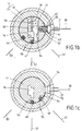
- FIGS. 1a to 1c show an initial rotational position of the cylinder core 11. This rotational position is illustrated by the auxiliary line 50 in Fig. 1b.
- a locking bar 40 is extended radially and engages its outer working end 42 in a housing groove 43; it looks like a tumbler and blocks a rotation of the cylinder core according to FIG. 1b 11.
- the locking bar 40 is in its "locking position" in FIGS. 1a to 1c.
- FIG. 2b shows the same starting rotary position 50 of the cylinder core 11 1b, as can be seen from the rotational position of the locking bar 40.
- the locking bar 40 is also spring-loaded in the direction of arrow 44.
- the spring means causing this is not shown in detail in the figures. Therefore, while the aforementioned radial alignment is present, this can be done Retract the control end 41 of the locking bar 40 into the recess 34. Then the locking bar working end 42 is removed from the housing groove 43. At inserted key 17 is consequently that of the locking bar 40 so far caused blockage, the locking bar is in your "Release position" and the cylinder core 11 is in the key operation Direction of arrow 14 rotatable.
- the present exemplary embodiment is a so-called Ignition starter switch in a motor vehicle. Only if its cylinder core 11 is in the initial rotational position 50 of Fig. 1a to 1c, it is possible to insert the key 17 into the key channel 16, which in 2a and 2b is illustrated, or to pull out again. Only in this starting rotary position 50 are the tumblers 13 with the locking channels mentioned in the housing 12 radially aligned and leave move radially. Without a properly inserted key in the starting rotary position 50, the motor vehicle electrical system is switched off. In the present invention, as long as the proper key 17 is not fully retracted into the cylinder core 11, d. H. in the situation 1 to 1c, also the evaluator 20 inactive.
- the locking bar 40 made of a magnetic material 45 that the locking bar 40 to a radial makes movable "permanent magnet”.
- the use of the magnetic material 45 in the locking bar 40 is in by a slight dot hatching the drawings.
- This permanent magnet 40 is a assigned first sensor H1, which is in a suitable receptacle 35 from Cylinder housing 12 is attached.
- the sensor H1 is a Hall element, that in the zone of the cylinder housing identified by 38 in FIG. 1a 12 is arranged.
- a further receptacle 36 is provided for a further sensor H2, which is also a Hall element.
- the evaluator 20 is activated the corresponding units in the motor vehicle via a data line, such as an on-board computer, the corresponding control devices, for. Legs Immobilizer, acts. Although this is in Fig. 7 by a first output line 23 illustrates, but this could also apply to all of them Output lines 23 to 26 replacing, common bus line take place, which the digital data generated by the evaluator via the code a central electrical system in the motor vehicle conducts.
- the evaluator 20 is in accordance with 7 is provided with a power supply 27 and via line 28 connected to ground.
- Fig. 1b and 1c are in the corresponding Axial zones 58, 59 of the cylinder core 11 further permanent magnets 55 provided that not radially movable, like the locking bar 40, but firmly embedded in suitable recesses 54 in the peripheral surface are.
- the permanent magnets 55 can thus be flush with the peripheral surface of the cylinder core 11 lie.
- These permanent magnets 55 are in the Drawings highlighted by dot hatching. Given the construction of the lock cylinder 10, the permanent magnets 55 have a somewhat higher magnetic field strength than that which builds the locking bar 40 Magnetic material 45. This is different in the drawings by one dense hatching illustrates.
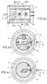
- the cylinder core 11 is by a key turn 14 come into a first working position 51, in which the application on an ignition switch in the device, the automotive electrical system is switched on.
- This working position 51 is also called the "radio position". With an ignition starter switch one speaks in this working position 51 from a power supply of a "terminal R" of the associated switching device.
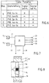
- This working position 51 of the cylinder core 11 is not Locking elements shown in more detail fixed and at the key turn 14 noticeable. In this rotational position, the locking bar 40 has further removed from the sensor H1, which is why, as in the third line of the 6 can be seen, no signal to the evaluator 20 passes.
- a permanent magnet 55 has aligned itself radially with the sensor H2.
- This permanent magnet 55 is namely at a peripheral point 48 of this zone 59, which when turned into the working position 51 comes close to sensor H2.
- Receives via its sensor output 22 the evaluator 20 outputs a signal as from the third line of the code table 6 can be seen.
- the evaluator 20 clearly sets this first working position 51 of the cylinder core 11 firm. Because the evaluator is like an electronic switching device acts, it issues the appropriate control commands to the units or the on-board computer controlling these units. This is based on the Fig. 7 thereby illustrates that now a control signal via the second Output line 24 is released. In technical terms, this means that the "terminal R" is activated.
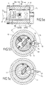
- the cylinder core 11 is so far according to the arrow 14 has been rotated that a second working position 52 has been achieved is.
- a second working position 52 is located in the two axial zones 58, 59 of the cylinder core the circumferential points marked with 47 and 49, which then with the two sensors H1, H2 are aligned in the cylinder housing 12, further Permanent magnets 55.
- This working position 52 also goes through Locking elements noticeable, which can be felt when turning the key 17 are.
- the evaluator 20 provides at both sensor outputs 21, 22 a signal as stated in the fourth line of the code table Fig. 6 can be seen.
- the cylinder core 11 is rotated as far as arrow 14 that a third defined working position 53 has been reached is.
- This third working position 53 can be done by a on the cylinder core 11 effective end stop.
- a permanent magnet 55 In this case is located only at the circumferential point 46 in that belonging to the sensor H1 Axial zone 58 from the cylinder core 11, a permanent magnet 55, while in the other axial zone 59 an empty circumferential location of the cylinder core 11 appears.
- the first sensor H1 detects a signal that reaches the evaluator 20 via the sensor output 21.
- the H2 sensor does not provide a signal.
- the evaluator 20 provides the code "yes / no" according to the last line of the code table of FIG. 6.
- the evaluator 20 which acts as an electronic switching device, is activated in this case the starter in the motor vehicle.
- the Cylinder core 11 of an ignition starter switch under the action of an angular momentum spring, who strives to release the key 17 the cylinder core 11 by itself in the second working position of FIGS. 4a to 4c.
- the evaluator 20 also provides the latter on the basis of this changing code "yes / yes" evident from FIG.
- FIG. 8 is a fragment of a locking cylinder according to the invention 10 'shown in an alternative embodiment.
- the difference compared the above-described first embodiment is that in that axial zone 38, where a sensor H2 sits in the cylinder housing Ring or a ring segment 56 made of magnetizable material in the cylinder core 11 'is arranged. At that peripheral point of the cylinder core 11 ', on which the permanent magnets 55' which can be determined as a code according to 8, the material is a polarized magnetization subjected. Then a sensor H2 sets at defined ring sections 57 the magnetic field is fixed and the evaluator 20 determines it again the respective working positions via the code.
- the one as a permanent magnet Ring portion 57 acting in FIG. 8 is illustrated by dot hatching. In Fig. 8 the radial alignment of this is by magnetization relevant ring section 57 shown with the sensor H2. This matches with the first working position of the cylinder core shown in FIGS. 3a to 3c 11 '.
- the design of the lock cylinder 10 'shown in FIG. 8 allows that First all cylinder cores - regardless of the desired code - can be prefabricated.
- the arrangement of the permanent magnets 55 ' according to the individual coding of the rotary positions of the cylinder cores 11 'then takes place through the corresponding magnetization 55' of the relevant one Ring sections 57. You could magnetize the defined Ring sections 57 of the rings or ring segments 56 but also before perform their installation in the cylinder core 11 '.
- the number of sensors H1, H2 and their arrangement, depending on the application, could also be designed differently. This applies also for the number and position of the permanent magnets. If necessary could be on the use of a radially movable from the key 17 Do not use locking bar 40 or this locking bar 40 is not made of magnetic material Train 45.
- the locking bar signals 40 because of their magnetic material 45 the evaluator 20, whether the right one Key is inserted in the cylinder core 11 or not. That becomes the activation and deactivation of the evaluator 20, the on-board computer or the central electrical system.
- the magnetic field strength of the individual permanent magnets 55 or those that arise in places due to magnetization Permanent magnets 55 'could have a different magnetic field strength or magnetic field direction, which of the sensors H1, H2 could be observed and also evaluated. With these measures the variety of the code would increase considerably. Man could then already in an axial zone 38 and / or 39 by different Magnets 55 or magnetizations 55 'with respect to direction and / or Strength of the magnetic field arrange enough information to the respective individual working position 51, 52, 53 of the cylinder core 11 or 11 ' to be able to determine a single sensor H1 or H2. In this case only the number of sensors and the differences of the permanent magnets vary at the specific circumferential locations of the cylinder core 11 or 11 '.
Landscapes
- Engineering & Computer Science (AREA)
- Mechanical Engineering (AREA)
- Physics & Mathematics (AREA)
- General Physics & Mathematics (AREA)
- Lock And Its Accessories (AREA)
Claims (9)
- Dispositif avec un cylindre de serrure (10) susceptible d'être actionné par une clé et avec un organe de commutation,caractérisé en ce que :qui, en fonction de la rotation correspondante (14) de la clé rend active ou inactive une fonction électrique déterminée dans un véhicule ou similaire,en particulier un commutateur de mise en service de l'allumage pour un véhicule automobile,le cylindre de serrure (10) se composant d'un boítier de cylindre (12) localement fixe et d'un noyau de cylindre (11) monté à rotation dans le boítier,noyau qui - en partant d'une position de rotation (50) de départ - est déplacé par la rotation (14) de la clé au choix dans l'une parmi plusieurs positions de travail (51, 52, 53) définies, et dans lequel l'organe de commutation réalise chaque fois dans le véhicule ou similaire une fonction électrique spécifique pour cette position de travail,dans lequel dispositif sont prévus à l'intérieur du noyau (11) de cylindre des paillettes de gorge extérieures (13) pour verrouiller en rotation le noyau dans le boítier de cylindre (12) et également un canal de clé (16) pour la réception de la clé (17) afin de déverrouiller le noyau de cylindre (11),et dans lequel des aimants permanents (55) sont disposés à la périphérie du noyau (11) du cylindre,et dans lequel, dans le boítier de cylindre (12) hors d'au moins un canal de blocage pour les paillettes de gorge (13) sont également encore disposés sur les aimants permanents (55) du noyau de cylindre, des capteurs correspondants,le boítier de cylindre (12) porte dans des zones (58, 59) décalées longitudinalement (en 29) les unes par rapport aux autres, au moins deux capteurs (H1, H2) dont les sorties de capteur (21, 22) sont reliées à un déclencheur (20) commun,et en ce que le noyau de cylindre (11) comporte dans les zones axiales (58, 59) correspondantes plusieurs aimants permanents (40, 55) aux emplacements périphériques conjugués (46, 47, 48, 49),qui, en collaboration avec les capteurs (H1, H2), livrent aux sorties (21, 22) des capteurs un codage électrique discriminant la position en rotation (50) de départ etles diverses positions de travail (51, 52, 53) du noyau (11) de cylindre,et en ce que le déclencheur (20), non seulement identifie nettement via les codes la position en rotation (50) de départ et la position de travail correspondante (51, 52, 53) du noyau (11) de cylindre, mais également déclenche - à l'aide du code déterminé - la fonction électrique dans le véhicule ou similaire, appartenant à cette position de travail (51, 52, 53).
- Dispositif selon la revendication 1, caractérisé en ce que les capteurs (H1, H2) dans le boítier de cylindre (12) sont sensiblement alignés axialement les uns par rapport aux autres.
- Dispositif selon la revendication 1 ou 2, caractérisé en ce que le noyau (11) de cylindre comporte dans chacune des zones axiales (58, 59) alignées avec l'un des capteurs (H1, H2), au moins deux aimants permanents (55) et en ce que - par comparaison du modèle d'agencement des aimants dans les zones axiales individuelles (58, 59) - au moins l'un des aimants permanents (55) est placé sur une position périphérique (46, 47, 48, 49) décalée en rotation, caractérisant une autre position de travail (51, 52, 53) du noyau (11) de cylindre.
- Dispositif selon l'une ou plusieurs des revendications 1 à 3, avec, dans le noyau (11) de cylindre, une barrette de blocage (40) mobile radialement et qui est en fait retenue, lorsque la clé (17) est retirée, dans une position de blocage faisant saillie radialement sur la périphérie du cylindre, position dans laquelle elle s'engage dans une rainure (43) prévue dans le boítier (12) de cylindre et empêche la rotation (14),
mais qui, lorsque la clé (17) est enfichée correctement, passe dans une position de libération rentrée, où elle libère la rainure (43) de boítier et autorise la rotation (14) du cylindre par l'intermédiaire de la clé (17),
caractérisé en ce que :la barrette de blocage (40) est magnétisable ou bien est elle-même un aimant permanent (45), auquel est associé un capteur de barrette (H1) réagissant au champ magnétique de la barrette ou de l'aimant,et en ce que le capteur de barrette (H1) est placé sur un emplacement conjugué intérieur du boítier de cylindre, emplacement qui est alors aligné de façon sensiblement radiale avec la barrette de blocage (40),lorsque le noyau (11) de cylindre se trouve dans sa position de rotation (50) de départ où l'enfichage et le retrait de la clé (17) dans et respectivement hors de son canal de clé (16) sont possibles,et en ce que le capteur de barrette (H1), dès l'enfichage de la clé correcte (17) réagit à la variation de champ magnétique, qui se produit à la suite de l'abaissement de la barrette de blocage (40) de sa position de blocage à sa position de libération,et en ce que le déclencheur (20) réagit à ce signal et fixe la position de rotation (50) de départ avec la clé correcte (17) enfichée. - Dispositif selon la revendication 4, caractérisé en ce que le déclencheur (20) dans la position de rotation (50) de départ, lorsque la clé n'est pas enfichée, reste dans une position inactive, mais en ce que le déclencheur (20) est activé par le signal déclenché par la variation de champ magnétique au cours de l'abaissement de la barrette de blocage (40).
- Dispositif selon la revendication 5, caractérisé en ce que l'activation du déclencheur (20) est réalisée seulement lorsque la variation de champ magnétique captée se trouve à l'intérieur de valeurs limites déterminées.
- Dispositif selon l'une ou plusieurs des revendications 4 à 6, caractérisé en ce que le capteur de barrette (H1) au cours de la rotation (14) du noyau (11) de cylindre réagit également aux aimants permanents (55) ou aux autres aimants permanents (55) non mobiles radialement,
qui sont disposés dans la même zone axiale (58) que la barrette de blocage (40) mobile radialement. - Dispositif selon l'une ou plusieurs des revendications 1 à 7, caractérisé en ce que le noyau (11') de cylindre comporte dans chaque zone axiale une bague ou un segment (56) de bague en matière magnétisable et qui est aligné avec l'un des capteurs (H2),
et en ce que l'aimant permanent (55') est créé dans une partie de bague définie (57) à l'emplacement périphérique souhaité du noyau (11') de cylindre par une magnétisation polarisée du matériau de la bague ou du segment (56) de bague. - Dispositif selon l'une ou plusieurs des revendications 1 à 8, caractérisé en ce que les capteurs (H1, H2) réagissent à des amplitudes différentes de champ magnétique et/ou à des directions différentes de champ magnétique des aimants permanents (55, 55') disposés aux divers emplacements de la périphérie différents les uns des autres, ces amplitudes différentes et/ou ces directions différentes étant enregistrées par le déclencheur (20) comme des codes différents.
Applications Claiming Priority (3)
| Application Number | Priority Date | Filing Date | Title |
|---|---|---|---|
| DE19645461 | 1996-11-05 | ||
| DE19645461 | 1996-11-05 | ||
| PCT/EP1997/004940 WO1998019897A1 (fr) | 1996-11-05 | 1997-09-10 | Dispositif avec un cylindre de fermeture et un commutateur de fonctions electriques diverses, notamment contacteur d'allumage pour vehicules a moteur |
Publications (2)
| Publication Number | Publication Date |
|---|---|
| EP0935543A1 EP0935543A1 (fr) | 1999-08-18 |
| EP0935543B1 true EP0935543B1 (fr) | 2001-07-25 |
Family
ID=7810632
Family Applications (2)
| Application Number | Title | Priority Date | Filing Date |
|---|---|---|---|
| EP97909241A Expired - Lifetime EP0935543B1 (fr) | 1996-11-05 | 1997-09-10 | Dispositif avec un cylindre de fermeture et un commutateur de fonctions electriques diverses, notamment contacteur d'allumage pour vehicules a moteur |
| EP97913183A Expired - Lifetime EP0938617B1 (fr) | 1996-11-05 | 1997-10-29 | Dispositif muni d'un cylindre de fermeture pouvant etre actionne avec une clef et d'un systeme de commutation electrique, notamment un systeme de blocage electronique interdisant l'usage non autorise d'une automobile |
Family Applications After (1)
| Application Number | Title | Priority Date | Filing Date |
|---|---|---|---|
| EP97913183A Expired - Lifetime EP0938617B1 (fr) | 1996-11-05 | 1997-10-29 | Dispositif muni d'un cylindre de fermeture pouvant etre actionne avec une clef et d'un systeme de commutation electrique, notamment un systeme de blocage electronique interdisant l'usage non autorise d'une automobile |
Country Status (11)
| Country | Link |
|---|---|
| US (2) | US6236121B1 (fr) |
| EP (2) | EP0935543B1 (fr) |
| JP (2) | JP2001503825A (fr) |
| KR (2) | KR100482388B1 (fr) |
| CN (2) | CN1088017C (fr) |
| AU (2) | AU716917B2 (fr) |
| BR (2) | BR9712870A (fr) |
| DE (3) | DE59704146D1 (fr) |
| ES (2) | ES2158508T3 (fr) |
| PT (2) | PT935543E (fr) |
| WO (2) | WO1998019897A1 (fr) |
Families Citing this family (29)
| Publication number | Priority date | Publication date | Assignee | Title |
|---|---|---|---|---|
| DE19842224C2 (de) * | 1998-09-15 | 2002-10-17 | Siemens Ag | Zündanlaßschaltermodul sowie Verfahren zum Herstellen eines Zündanlaßschaltermoduls |
| DE19938888C2 (de) * | 1999-08-17 | 2002-01-17 | Siemens Ag | Zündanlaßschalter |
| JP2001063395A (ja) * | 1999-08-31 | 2001-03-13 | Tokai Rika Co Ltd | 不正使用防止用シフトレバーロック装置 |
| DE19951987C1 (de) * | 1999-10-28 | 2001-06-28 | Huf Huelsbeck & Fuerst Gmbh | Schlüsselbetätigbarer Zündanlassschalter für Kraftfahrzeuge |
| DE10129095C1 (de) * | 2001-06-16 | 2003-03-20 | Siemens Ag | Elektrische Lenkungsverriegelung |
| KR101133305B1 (ko) * | 2004-02-12 | 2012-04-04 | 후프 노쓰 아메리카 오토모티브 파츠 엠에프지. 코프. | 스티어링 록 조립체 |
| ATE495065T1 (de) * | 2004-08-11 | 2011-01-15 | Marquardt Gmbh | Zündschloss für ein kraftfahrzeug |
| US7360382B2 (en) * | 2005-02-08 | 2008-04-22 | Huf North America Parts Mfg. Corp. | Cylinder lock assembly |
| US7969705B2 (en) | 2005-03-30 | 2011-06-28 | Strattec Security Corporation | Residual magnetic devices and methods |
| US20060219497A1 (en) * | 2005-03-30 | 2006-10-05 | Organek Gregory J | Residual magnetic devices and methods |
| US20060220393A1 (en) * | 2005-03-30 | 2006-10-05 | Dimig Steven J | Residual magnetic devices and methods |
| US8403124B2 (en) | 2005-03-30 | 2013-03-26 | Strattec Security Corporation | Residual magnetic devices and methods |
| US20060225973A1 (en) * | 2005-03-30 | 2006-10-12 | Dimig Steven J | Residual magnetic devices and methods |
| JP4767593B2 (ja) * | 2005-06-02 | 2011-09-07 | 株式会社ホンダロック | 車両用イグニッションスイッチの操作装置 |
| DE102005061231B4 (de) * | 2005-12-20 | 2020-04-09 | Huf Hülsbeck & Fürst Gmbh & Co. Kg | Zylinderkern |
| DE102006054412A1 (de) * | 2006-07-31 | 2008-02-07 | Conti Temic Microelectronic Gmbh | Kontaktloser Schalter |
| WO2008034022A2 (fr) | 2006-09-14 | 2008-03-20 | The Knox Company | Ensemble électronique de clé et verrou |
| FR2907828B1 (fr) * | 2006-10-30 | 2009-01-30 | Valeo Securite Habitacle Sas | Rotor de verrou pour vehicule automobile |
| KR100796275B1 (ko) * | 2007-01-29 | 2008-01-21 | 수성정밀기계(주) | 도난방지장치 |
| US8276415B2 (en) * | 2009-03-20 | 2012-10-02 | Knox Associates | Holding coil for electronic lock |
| DE102011114286A1 (de) * | 2010-09-30 | 2013-01-24 | Dom Sicherheitstechnik Gmbh & Co. Kg | Sensorvorrichtung mit Drehrichtungserfassung |
| CN102709097A (zh) * | 2012-05-17 | 2012-10-03 | 黄山奥特斯电气有限公司 | 一种点火开关 |
| DE102012111606A1 (de) * | 2012-11-29 | 2014-04-10 | Dr. Ing. H.C. F. Porsche Aktiengesellschaft | Zylindergehäuse |
| US9041510B2 (en) | 2012-12-05 | 2015-05-26 | Knox Associates, Inc. | Capacitive data transfer in an electronic lock and key assembly |
| DE102013106398A1 (de) * | 2013-06-19 | 2014-12-24 | Brose Fahrzeugteile Gmbh & Co. Kommanditgesellschaft, Hallstadt | Erfassungseinrichtung für die Erfassung von mechanischen Funktionszuständen eines Kraftfahrzeugschlosses |
| CN104599356A (zh) * | 2014-12-24 | 2015-05-06 | 科世达(上海)管理有限公司 | 一种通信部件与开关集成装置和集成方法 |
| USD881677S1 (en) | 2017-04-27 | 2020-04-21 | Knox Associates, Inc. | Electronic key |
| CN113332048B (zh) * | 2021-06-08 | 2022-05-27 | 吉林大学 | 一种心内科护理用可伸缩翻转的转运装置 |
| US12509910B2 (en) * | 2022-11-21 | 2025-12-30 | Knox Associates, Inc. | Electronic lock core replacement methods |
Family Cites Families (15)
| Publication number | Priority date | Publication date | Assignee | Title |
|---|---|---|---|---|
| US3639772A (en) * | 1970-04-13 | 1972-02-01 | Zade Wilson | Ignition switching device |
| GB2026081A (en) | 1978-07-25 | 1980-01-30 | Ward R | Numerical, magnetically-encoded, electronically-sensed key |
| US4326124A (en) * | 1978-11-22 | 1982-04-20 | Bsg Schalttechnik Gmbh & Co. Kg. | Locking apparatus for preventing unauthorized access or actions |
| DE2853655A1 (de) * | 1978-12-13 | 1980-07-03 | Egon Gelhard | Zylinderschloss mit schluessel zur mechanischen und/oder elektromechanischen verriegelung |
| ES520422A0 (es) * | 1983-03-08 | 1984-03-16 | Zottnik Edmund | Sistema codificado de validacion y comando. |
| US4901053A (en) | 1986-02-28 | 1990-02-13 | Honda Lock Manufacturing Co., Ltd. | Anti-theft system for automotive vehicles |
| DE8710596U1 (de) * | 1987-08-03 | 1988-12-01 | DOM-Sicherheitstechnik GmbH & Co KG, 5040 Brühl | Zylinderbetätigbarer Schlüsselschalter |
| US4803467A (en) * | 1988-02-23 | 1989-02-07 | George Peters | Magnetic key lock provided with an alarm system |
| AU5777090A (en) * | 1990-06-25 | 1992-01-02 | Kiyoyasu Wake | Burglarproof device for vehicle |
| US5202580A (en) * | 1990-11-01 | 1993-04-13 | Briggs & Stratton | Anti-tampering magnet for automobile ignition lock |
| US5455571A (en) * | 1991-02-11 | 1995-10-03 | Strattec Security Corporation | Fail safe system for a mechanical lock key set with electronic interlock |
| US5186031A (en) * | 1991-08-20 | 1993-02-16 | Briggs & Stratton Corporation | Self-destruct electrical interlock for cylinder lock and key set |
| US5551267A (en) * | 1994-04-15 | 1996-09-03 | Briggs & Stratton Corporation | Anti-magnetic tampering system for automobile ignition lock |
| DE9415257U1 (de) * | 1994-09-20 | 1994-11-17 | Siemens AG, 80333 München | Näherungsschalter mit drei Schaltpositionen |
| DE19547304A1 (de) | 1994-12-20 | 1996-06-27 | Gen Motors Corp | Fahrzeugdiebstahlabschreckungssystem |
-
1997
- 1997-09-10 WO PCT/EP1997/004940 patent/WO1998019897A1/fr not_active Ceased
- 1997-09-10 BR BR9712870-8A patent/BR9712870A/pt not_active IP Right Cessation
- 1997-09-10 KR KR10-1999-7003959A patent/KR100482388B1/ko not_active Expired - Fee Related
- 1997-09-10 ES ES97909241T patent/ES2158508T3/es not_active Expired - Lifetime
- 1997-09-10 US US09/297,461 patent/US6236121B1/en not_active Expired - Fee Related
- 1997-09-10 AU AU47017/97A patent/AU716917B2/en not_active Ceased
- 1997-09-10 PT PT97909241T patent/PT935543E/pt unknown
- 1997-09-10 CN CN97199468A patent/CN1088017C/zh not_active Expired - Fee Related
- 1997-09-10 JP JP52097698A patent/JP2001503825A/ja not_active Ceased
- 1997-09-10 EP EP97909241A patent/EP0935543B1/fr not_active Expired - Lifetime
- 1997-09-10 DE DE59704146T patent/DE59704146D1/de not_active Expired - Lifetime
- 1997-10-29 CN CN97199470A patent/CN1237221A/zh active Pending
- 1997-10-29 BR BR9712890-2A patent/BR9712890A/pt unknown
- 1997-10-29 JP JP52101698A patent/JP2001503826A/ja active Pending
- 1997-10-29 US US09/297,463 patent/US6201317B1/en not_active Expired - Fee Related
- 1997-10-29 KR KR1019990703960A patent/KR20000053053A/ko not_active Ceased
- 1997-10-29 ES ES97913183T patent/ES2169368T3/es not_active Expired - Lifetime
- 1997-10-29 AU AU50521/98A patent/AU722870B2/en not_active Ceased
- 1997-10-29 PT PT97913183T patent/PT938617E/pt unknown
- 1997-10-29 EP EP97913183A patent/EP0938617B1/fr not_active Expired - Lifetime
- 1997-10-29 DE DE19747720A patent/DE19747720A1/de not_active Withdrawn
- 1997-10-29 WO PCT/EP1997/005955 patent/WO1998020221A1/fr not_active Ceased
- 1997-10-29 DE DE59706519T patent/DE59706519D1/de not_active Expired - Lifetime
Also Published As
| Publication number | Publication date |
|---|---|
| WO1998019897A1 (fr) | 1998-05-14 |
| WO1998020221A1 (fr) | 1998-05-14 |
| CN1237131A (zh) | 1999-12-01 |
| EP0938617B1 (fr) | 2002-02-27 |
| KR100482388B1 (ko) | 2005-04-13 |
| DE19747720A1 (de) | 1998-05-07 |
| BR9712870A (pt) | 1999-12-07 |
| AU5052198A (en) | 1998-05-29 |
| BR9712890A (pt) | 2000-02-01 |
| DE59706519D1 (de) | 2002-04-04 |
| ES2169368T3 (es) | 2002-07-01 |
| PT938617E (pt) | 2002-07-31 |
| ES2158508T3 (es) | 2001-09-01 |
| DE59704146D1 (de) | 2001-08-30 |
| JP2001503825A (ja) | 2001-03-21 |
| AU4701797A (en) | 1998-05-29 |
| US6236121B1 (en) | 2001-05-22 |
| JP2001503826A (ja) | 2001-03-21 |
| KR20000053053A (ko) | 2000-08-25 |
| CN1088017C (zh) | 2002-07-24 |
| AU716917B2 (en) | 2000-03-09 |
| EP0935543A1 (fr) | 1999-08-18 |
| EP0938617A1 (fr) | 1999-09-01 |
| CN1237221A (zh) | 1999-12-01 |
| KR20000053052A (ko) | 2000-08-25 |
| AU722870B2 (en) | 2000-08-10 |
| PT935543E (pt) | 2001-11-30 |
| US6201317B1 (en) | 2001-03-13 |
Similar Documents
| Publication | Publication Date | Title |
|---|---|---|
| EP0935543B1 (fr) | Dispositif avec un cylindre de fermeture et un commutateur de fonctions electriques diverses, notamment contacteur d'allumage pour vehicules a moteur | |
| EP0278906B1 (fr) | Dispositif de fermeture électromécanique | |
| DE69304904T2 (de) | Zylinderschloss | |
| DE2327363C3 (de) | Schlüsselbetätigbare elektronisch gesteuerte Sperreinrichtung | |
| DE2928913C2 (de) | Diebstahl-Sicherungsvorrichtung für Kraftfahrzeuge | |
| DE10262209B4 (de) | Lenkradschlosseinrichtung | |
| DE19908085C1 (de) | Vorrichtung zur Aufnahme und Halterung eines Identifikationsgebers, wie eines elektronischen Schlüssels, insbesondere für einen Zündanlaßschalter und/oder eine Lenksäuleneverriegelung eines Motorfahrzeugs | |
| DE10119267C1 (de) | Lenkschloss für Fahrzeuge | |
| EP1135284B1 (fr) | Systeme de fermeture, notamment pour automobiles | |
| DE19752519A1 (de) | Verriegelungseinrichtung für Lenkungen von Kraftfahrzeugen | |
| DE3426508A1 (de) | Schaltschlossanlage | |
| EP0298193B1 (fr) | Cylindre de serrure à goupille électromagnétique | |
| DE102009005322B4 (de) | Elektronische Möbelschließeinheit | |
| DE3632904A1 (de) | Schliesseinrichtung fuer ein mechanisch/elektronisches schliess-system | |
| EP1384633A1 (fr) | Système de verrouillage pour véhicule à moteur | |
| EP1626142B1 (fr) | Mécanisme de blocage | |
| EP0918001A2 (fr) | Système de clé de contact éléctronique notamment pour véhicules à moteur | |
| DE3245681C2 (de) | Nichtmechanisch/mechanisch codierter Schlüssel mit damit zu betätigendem Schließzylinder | |
| DE19653860C1 (de) | Schließsystem für Kraftfahrzeuge | |
| EP0721869B1 (fr) | Dispositif de verrouillage pour véhicules | |
| EP1121278B1 (fr) | Dispositif de commande pour l'allumage et le blocage de la direction d'une automobile | |
| DE69613880T2 (de) | Verbesserte Diebstahlsicherung, insbesondere für ein Kraftfahrzeug | |
| DE69613878T2 (de) | Elektrische Diebstahlsicherung für ein Kraftfahrzeug | |
| DE69414807T2 (de) | Diebstahlschutzvorrichtung sowie Verfahren zu deren Steuerung für Kraftfahrzeuge mit fernsteuerbarer Verriegelung | |
| EP1029757A2 (fr) | Interrupteur d'allumage actionné manuellement pour un dispositif de contrôle d'autorisation sans clé du démarrage d'un véhicule à moteur |
Legal Events
| Date | Code | Title | Description |
|---|---|---|---|
| PUAI | Public reference made under article 153(3) epc to a published international application that has entered the european phase |
Free format text: ORIGINAL CODE: 0009012 |
|
| 17P | Request for examination filed |
Effective date: 19990318 |
|
| AK | Designated contracting states |
Kind code of ref document: A1 Designated state(s): DE ES FR GB IT NL PT SE |
|
| GRAG | Despatch of communication of intention to grant |
Free format text: ORIGINAL CODE: EPIDOS AGRA |
|
| GRAG | Despatch of communication of intention to grant |
Free format text: ORIGINAL CODE: EPIDOS AGRA |
|
| GRAH | Despatch of communication of intention to grant a patent |
Free format text: ORIGINAL CODE: EPIDOS IGRA |
|
| 17Q | First examination report despatched |
Effective date: 20001218 |
|
| GRAH | Despatch of communication of intention to grant a patent |
Free format text: ORIGINAL CODE: EPIDOS IGRA |
|
| ITF | It: translation for a ep patent filed | ||
| GRAA | (expected) grant |
Free format text: ORIGINAL CODE: 0009210 |
|
| AK | Designated contracting states |
Kind code of ref document: B1 Designated state(s): DE ES FR GB IT NL PT SE |
|
| REF | Corresponds to: |
Ref document number: 59704146 Country of ref document: DE Date of ref document: 20010830 |
|
| REG | Reference to a national code |
Ref country code: ES Ref legal event code: FG2A Ref document number: 2158508 Country of ref document: ES Kind code of ref document: T3 |
|
| GBT | Gb: translation of ep patent filed (gb section 77(6)(a)/1977) |
Effective date: 20010927 |
|
| REG | Reference to a national code |
Ref country code: PT Ref legal event code: SC4A Free format text: AVAILABILITY OF NATIONAL TRANSLATION Effective date: 20010726 |
|
| ET | Fr: translation filed | ||
| REG | Reference to a national code |
Ref country code: GB Ref legal event code: IF02 |
|
| PLBE | No opposition filed within time limit |
Free format text: ORIGINAL CODE: 0009261 |
|
| STAA | Information on the status of an ep patent application or granted ep patent |
Free format text: STATUS: NO OPPOSITION FILED WITHIN TIME LIMIT |
|
| 26N | No opposition filed | ||
| PGFP | Annual fee paid to national office [announced via postgrant information from national office to epo] |
Ref country code: PT Payment date: 20050718 Year of fee payment: 9 |
|
| PGFP | Annual fee paid to national office [announced via postgrant information from national office to epo] |
Ref country code: SE Payment date: 20050906 Year of fee payment: 9 |
|
| PGFP | Annual fee paid to national office [announced via postgrant information from national office to epo] |
Ref country code: ES Payment date: 20050908 Year of fee payment: 9 |
|
| PGFP | Annual fee paid to national office [announced via postgrant information from national office to epo] |
Ref country code: NL Payment date: 20050930 Year of fee payment: 9 |
|
| PGFP | Annual fee paid to national office [announced via postgrant information from national office to epo] |
Ref country code: GB Payment date: 20060821 Year of fee payment: 10 |
|
| PG25 | Lapsed in a contracting state [announced via postgrant information from national office to epo] |
Ref country code: SE Free format text: LAPSE BECAUSE OF NON-PAYMENT OF DUE FEES Effective date: 20060911 |
|
| PGFP | Annual fee paid to national office [announced via postgrant information from national office to epo] |
Ref country code: IT Payment date: 20060930 Year of fee payment: 10 |
|
| PG25 | Lapsed in a contracting state [announced via postgrant information from national office to epo] |
Ref country code: PT Free format text: LAPSE BECAUSE OF NON-PAYMENT OF DUE FEES Effective date: 20070312 |
|
| REG | Reference to a national code |
Ref country code: PT Ref legal event code: MM4A Free format text: LAPSE DUE TO NON-PAYMENT OF FEES Effective date: 20070312 |
|
| PG25 | Lapsed in a contracting state [announced via postgrant information from national office to epo] |
Ref country code: NL Free format text: LAPSE BECAUSE OF NON-PAYMENT OF DUE FEES Effective date: 20070401 |
|
| EUG | Se: european patent has lapsed | ||
| NLV4 | Nl: lapsed or anulled due to non-payment of the annual fee |
Effective date: 20070401 |
|
| REG | Reference to a national code |
Ref country code: ES Ref legal event code: FD2A Effective date: 20060911 |
|
| PG25 | Lapsed in a contracting state [announced via postgrant information from national office to epo] |
Ref country code: ES Free format text: LAPSE BECAUSE OF NON-PAYMENT OF DUE FEES Effective date: 20060911 |
|
| GBPC | Gb: european patent ceased through non-payment of renewal fee |
Effective date: 20070910 |
|
| PG25 | Lapsed in a contracting state [announced via postgrant information from national office to epo] |
Ref country code: GB Free format text: LAPSE BECAUSE OF NON-PAYMENT OF DUE FEES Effective date: 20070910 |
|
| PG25 | Lapsed in a contracting state [announced via postgrant information from national office to epo] |
Ref country code: IT Free format text: LAPSE BECAUSE OF NON-PAYMENT OF DUE FEES Effective date: 20070910 |
|
| PGFP | Annual fee paid to national office [announced via postgrant information from national office to epo] |
Ref country code: FR Payment date: 20101005 Year of fee payment: 14 |
|
| PGFP | Annual fee paid to national office [announced via postgrant information from national office to epo] |
Ref country code: DE Payment date: 20100804 Year of fee payment: 14 |
|
| REG | Reference to a national code |
Ref country code: FR Ref legal event code: ST Effective date: 20120531 |
|
| PG25 | Lapsed in a contracting state [announced via postgrant information from national office to epo] |
Ref country code: FR Free format text: LAPSE BECAUSE OF NON-PAYMENT OF DUE FEES Effective date: 20110930 |
|
| PG25 | Lapsed in a contracting state [announced via postgrant information from national office to epo] |
Ref country code: DE Free format text: LAPSE BECAUSE OF NON-PAYMENT OF DUE FEES Effective date: 20130403 |
|
| REG | Reference to a national code |
Ref country code: DE Ref legal event code: R119 Ref document number: 59704146 Country of ref document: DE Effective date: 20130403 |