EP0935829B1 - Sortie secteur - Google Patents
Sortie secteur Download PDFInfo
- Publication number
- EP0935829B1 EP0935829B1 EP97910542A EP97910542A EP0935829B1 EP 0935829 B1 EP0935829 B1 EP 0935829B1 EP 97910542 A EP97910542 A EP 97910542A EP 97910542 A EP97910542 A EP 97910542A EP 0935829 B1 EP0935829 B1 EP 0935829B1
- Authority
- EP
- European Patent Office
- Prior art keywords
- contacts
- linkage
- mode
- outlet according
- contact carrier
- Prior art date
- Legal status (The legal status is an assumption and is not a legal conclusion. Google has not performed a legal analysis and makes no representation as to the accuracy of the status listed.)
- Expired - Lifetime
Links
- 238000001514 detection method Methods 0.000 claims description 10
- 230000004044 response Effects 0.000 claims description 4
- 230000001419 dependent effect Effects 0.000 claims 2
- 230000007246 mechanism Effects 0.000 description 17
- 230000008878 coupling Effects 0.000 description 5
- 238000010168 coupling process Methods 0.000 description 5
- 238000005859 coupling reaction Methods 0.000 description 5
- 238000010276 construction Methods 0.000 description 2
- 230000008901 benefit Effects 0.000 description 1
- 230000000694 effects Effects 0.000 description 1
- 230000003993 interaction Effects 0.000 description 1
- 230000000007 visual effect Effects 0.000 description 1
Images

Classifications
-
- H—ELECTRICITY
- H01—ELECTRIC ELEMENTS
- H01R—ELECTRICALLY-CONDUCTIVE CONNECTIONS; STRUCTURAL ASSOCIATIONS OF A PLURALITY OF MUTUALLY-INSULATED ELECTRICAL CONNECTING ELEMENTS; COUPLING DEVICES; CURRENT COLLECTORS
- H01R13/00—Details of coupling devices of the kinds covered by groups H01R12/70 or H01R24/00 - H01R33/00
- H01R13/66—Structural association with built-in electrical component
- H01R13/70—Structural association with built-in electrical component with built-in switch
- H01R13/713—Structural association with built-in electrical component with built-in switch the switch being a safety switch
- H01R13/7135—Structural association with built-in electrical component with built-in switch the switch being a safety switch with ground fault protector
-
- H—ELECTRICITY
- H01—ELECTRIC ELEMENTS
- H01R—ELECTRICALLY-CONDUCTIVE CONNECTIONS; STRUCTURAL ASSOCIATIONS OF A PLURALITY OF MUTUALLY-INSULATED ELECTRICAL CONNECTING ELEMENTS; COUPLING DEVICES; CURRENT COLLECTORS
- H01R13/00—Details of coupling devices of the kinds covered by groups H01R12/70 or H01R24/00 - H01R33/00
- H01R13/66—Structural association with built-in electrical component
- H01R13/70—Structural association with built-in electrical component with built-in switch
- H01R13/713—Structural association with built-in electrical component with built-in switch the switch being a safety switch
Definitions
- the present invention relates to a mains electrical outlet and more particularly to such an outlet provided with manual switching facilities.
- Mains electrical outlets are housed in standard size boxes and are usually either one-gang or two-gang. Attempts have been made in the past to provide switched electrical outlets with fault protection in the form of residual current devices but all previous attempts have either resulted in the need for nonstandard sized outlets or else the use of a two-gang box for a one-gang RCD protected outlet.
- GB-A-2169749 on which the preamble of claim 1 is based discloses such a mains electrical outlet incorporating automatic circuit protection and has contacts which are opened by fault detection provisions. The contacts are normally operated by a conventional rocker switch but if automatically opened as a result of a fault condition need to be reset by a separate push button. There is thus a need for a switched electrical outlet which has RCD protection but which will fit in a standard size housing.
- the present invention proposes to provide a switched mains electrical outlet comprising:
- a preferred embodiment utilises the normal electrical contact assembly for making and breaking the power contacts together with a normal construction of manually operable switching means.
- the linkage between these two elements is a controllable coupling operating in response to a fault detection mechanism.
- the controllable coupling is in the form of an axial clutch which is capable of axial movement in the presence of a fault condition to thereby effectively disengage the mains contacts from the manually operable switch member to permit the mains contacts to open but when there is no fault condition the mains contact operating mechanism is locked to the operation of the manually operable switch member.
- the preferred embodiment of the present invention is designed to result in a switched electrical outlet which has RCD protection built in but which occupies a standard outlet box.
- the preferred embodiment utilises as far as possible normal operating mechanisms but replaces the normal fixed linkage between the manually operable switch on the outlet and the actual mains contact mechanism with a controllable coupling mechanism.
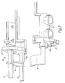
- the normal mains contact operating mechanism is indicated by the reference numeral 10.
- the mechanism consists of a contact carrier 12 carrying contacts 14 which in normal operation are biased by a biassing means 15 to a normally open condition with respect to fixed contacts 16.
- the contact carrier is arranged to rotate in a plane normal to the plane of the paper in Figure 1.
- a manually operable switch mechanism is generally indicated by reference numeral 18 and consists of a rocker switch 19 which is of the usual bistable type resulting from the use of an over-centre spring arrangement "where the rotational force required to overcome the spring to turn from on to off is greater than the rotational force exerted by the biasing spring 15, such that the switch system as a whole is also bi-stable for as long as the device is untripped.
- a controllable coupling mechanism 20 in the form of an axial clutch.
- the axial clutch is formed by a plate member 21 which faces a side wall 22 of the contact carrier 12.
- the facing surfaces 21,22 are provided with one or more inter-engaging projections and recesses; the projections 22a being shown in more detail in Figure 3.
- the plate 21 is arranged to be movable by the manually operable mechanism 18 in a rotational direction in and out of the paper as seen in Figure 1 but is capable of transverse or axial movement i.e to the left and right as shown in Figure 1 under the control of a fault detection system indicated generally by the reference numeral 28.
- the arrangement is such that the fault detection mechanism 28 in the absence of a fault, causes the plate 21 to be held in engagement with the surface 22 on the contact carrier 12 so that movement of the manually operable mechanism 18 will also move the contact carrier 12 to open or close the power contacts.
- This is achieved by interposing a movable member 23 between a surface 24 provided on an extension 25 to the plate 21 and a relatively fixed surface 26.
- the member 23 interposed between the surface 24 and fixed member 26 prevents any axial movement of the plate 21.
- the member 23 is withdrawn which allows relative movement between the members 24 and 26 which thus permits the plate 21 to move axially as a result of interaction between the projections and recesses on the contact carrier 12 and plate 21.
- the projections 22a and recesses have angled engaging surfaces which are designed so that the biassing means 15 exerts a sufficient rotational force on the contact carrier 12 to force the plate away from the surface 22 when the moveable member 23 is not interposed between the surface 24 and fixed surface 26.
- a further advantage of the above arrangement is that in order to reset a socket which has been tripped by a fault condition, all that is required is that the switch rocker 19 be returned to the "off' position and then placed into the "on" position again. If the fault has been cleared in the meantime then the switch will reset. However, if the fault is still present the operation of the rocker switch will have no effect on the contact carrier 12 due to the fact that the plate 21 will simply move axially as it also moves rotationally in response to operation of the rocker 19.
- Figure 3 shows in an exploded perspective view a portion of the contact carrier 12 with the flag attached as well as the controlled coupling member. Rather than repeat the above description the same reference numerals have been used in Figure 3 as have been used in Figure 1.
- the arms 31 engage the rocker switch 19 and cause the contact carrier to move with the rocker switch 19 in the absence of a fault.
Landscapes
- Details Of Connecting Devices For Male And Female Coupling (AREA)
- Finger-Pressure Massage (AREA)
- Reciprocating, Oscillating Or Vibrating Motors (AREA)
- Amplifiers (AREA)
- Organic Insulating Materials (AREA)
- Emergency Protection Circuit Devices (AREA)
Claims (12)
- Sortie électrique secteur commutée comprenant :caractérisée en ce que le moyen (12) de support de contact est agencé pour tourner autour d'un axe pour permettre la fermeture des premiers et deuxièmes contacts (14, 16) et le moyen de commutation (18) actionnable manuellement est agencé pour tourner autour d'un axe, et en ce qu'il y a un moyen de liaison (20) entre le moyen (12) de support de contact et le moyen de commutation (18) actionnable manuellement capable d'adopter l'un de deux modes de fonctionnement en réponse au moyen de détection d'erreur, dans laquelledes premiers contacts (16) ;des deuxièmes contacts (14) montés sur un moyen (12) de support de contact agencé pour être mobile pour permettre aux deuxièmes contacts de se fermer avec les premiers contacts ;un moyen de commutation (18) actionnable manuellement ; etun moyen (22) de détection d'erreur agencé pour commander le mode de fonctionnement pour ouvrir automatiquement les premiers et deuxièmes contacts (14, 16) en présence d'une erreur ;dans le premier mode de fonctionnement, le moyen de liaison (20) conduit le moyen (12) de support de contact à coopérer axialement avec le moyen de commutation (18) actionnable manuellement afin d'empêcher une rotation relative entre eux, aux fins de permettre aux premiers et deuxièmes contacts (14, 16) d'être commutés à l'état fermé ; et dans laquelledans le deuxième mode de fonctionnement, le moyen de liaison (20) conduit le moyen de support de contact à se libérer axialement du moyen de commutation actionnable manuellement afin de permettre une rotation relative entre eux, aux fins de permettre aux premiers et deuxièmes contacts de s'ouvrir ou de rester ouverts en présence d'une erreur.
- Sortie selon la revendication 1, comprenant en outre un moyen (15) de retour de support de contact agencé pour faire tourner le moyen de support de contact pour ouvrir les contacts dans le deuxième mode de fonctionnement de la liaison.
- Sortie selon la revendication 2, dans laquelle le moyen (15) de retour de support de contact est un ressort.
- Sortie selon l'une quelconque des revendications précédentes, dans laquelle la liaison (20) se présente sous la forme d'un embrayage mobile axialement pouvant être commandé.
- Sortie selon la revendication 4, dans laquelle l'embrayage mobile axialement comprend :une première plaque comportant un certain nombre de cavités angulaires ; etune deuxième plaque (22) comportant un nombre correspondant de broches angulaires (22a) agencées pour s'adapter dans les cavités lorsque les plaques (21, 22) coopèrent mutuellement ;dans laquelle, lors de l'application d'un mouvement de torsion à l'embrayage, les broches (22a) et les cavités angulaires créent une force axiale qui, dans le deuxième mode de fonctionnement, est suffisante pour libérer les plaques et dans le premier mode de fonctionnement, n'est pas suffisante pour libérer les plaques.
- Sortie selon l'une quelconque des revendications précédentes, comprenant en outre un moyen (30) pour indiquer si les contacts sont ouverts ou fermés.
- Sortie selon la revendication 6, dans laquelle le moyen d'indication (30) se présente sous la forme d'un élément mécanique qui est visible par un utilisateur lorsque les contacts sont fermés.
- Sortie selon l'une quelconque des revendications 1 à 4, dans laquelle le moyen de commutation actionnable manuellement se présente sous la forme d'un interrupteur à bascule (19).
- Sortie selon la revendication 8 lorsqu'elle dépend de la revendication 6 ou 7, dans laquelle l'interrupteur à bascule (19) est pourvu d'une ouverture à travers laquelle le moyen d'indication (30) est visible.
- Sortie selon l'une quelconque des revendications précédentes, dans laquelle le moyen (22) de détection d'erreur comporte un dispositif (22, 23) actionnable électriquement agencé pour commander le mode de fonctionnement de la liaison (20).
- Sortie selon la revendication 10, dans laquelle le dispositif actionnable électriquement comprend une bobine de solénoïde (22) dont l'armature (23) est agencée pour coopérer avec la liaison pour commander le mode de fonctionnement adopté par la liaison (20).
- Sortie selon la revendication 10 lorsqu'elle dépend de la revendication 4 ou 5, dans laquelle le dispositif actionnable électriquement comprend une bobine de solénoïde (22) dont l'armature (23) est agencée pour empêcher un déplacement axial de l'embrayage (21, 22) lorsque la liaison (20) est dans le premier mode de fonctionnement, et pour permettre un déplacement axial de l'embrayage lorsque la liaison est dans le deuxième mode de fonctionnement.
Applications Claiming Priority (3)
| Application Number | Priority Date | Filing Date | Title |
|---|---|---|---|
| GB9622732 | 1996-10-31 | ||
| GBGB9622732.7A GB9622732D0 (en) | 1996-10-31 | 1996-10-31 | Mains electrical outlet |
| PCT/GB1997/002985 WO1998019367A1 (fr) | 1996-10-31 | 1997-10-30 | Sortie secteur |
Publications (2)
| Publication Number | Publication Date |
|---|---|
| EP0935829A1 EP0935829A1 (fr) | 1999-08-18 |
| EP0935829B1 true EP0935829B1 (fr) | 2001-01-24 |
Family
ID=10802266
Family Applications (1)
| Application Number | Title | Priority Date | Filing Date |
|---|---|---|---|
| EP97910542A Expired - Lifetime EP0935829B1 (fr) | 1996-10-31 | 1997-10-30 | Sortie secteur |
Country Status (7)
| Country | Link |
|---|---|
| EP (1) | EP0935829B1 (fr) |
| KR (1) | KR100478566B1 (fr) |
| AT (1) | ATE198951T1 (fr) |
| AU (1) | AU4788997A (fr) |
| DE (1) | DE69703987T2 (fr) |
| GB (1) | GB9622732D0 (fr) |
| WO (1) | WO1998019367A1 (fr) |
Family Cites Families (6)
| Publication number | Priority date | Publication date | Assignee | Title |
|---|---|---|---|---|
| DE964969C (de) * | 1954-05-29 | 1957-05-29 | Licentia Gmbh | Schaltgeraet, insbesondere Installations-Selbstschalter mit thermischer und magnetischer Ausloesung |
| DE7541613U (de) * | 1975-12-29 | 1978-02-16 | Ellenberger & Poensgen Gmbh, 8503 Altdorf | Schalter mit einem kippbaren Schalthebel |
| US4399420A (en) * | 1981-09-11 | 1983-08-16 | Square D Company | Main circuit breaker |
| GB2169749A (en) * | 1985-01-12 | 1986-07-16 | Ashley Accessories Ltd | Electrical outlet accessories with incorporated automatic circuit breaker |
| CH673175A5 (fr) * | 1987-07-22 | 1990-02-15 | Bbc Brown Boveri & Cie | |
| DE3802765A1 (de) * | 1988-01-30 | 1989-08-10 | Insta Elektro Gmbh & Co Kg | Schaltvorrichtung fuer ein elektrisches installationsgeraet, insbesondere 2-polig abschaltbare steckdose |
-
1996
- 1996-10-31 GB GBGB9622732.7A patent/GB9622732D0/en active Pending
-
1997
- 1997-10-30 WO PCT/GB1997/002985 patent/WO1998019367A1/fr not_active Ceased
- 1997-10-30 DE DE69703987T patent/DE69703987T2/de not_active Expired - Fee Related
- 1997-10-30 EP EP97910542A patent/EP0935829B1/fr not_active Expired - Lifetime
- 1997-10-30 AT AT97910542T patent/ATE198951T1/de not_active IP Right Cessation
- 1997-10-30 AU AU47889/97A patent/AU4788997A/en not_active Abandoned
- 1997-10-30 KR KR10-1999-7003775A patent/KR100478566B1/ko not_active Expired - Fee Related
Also Published As
| Publication number | Publication date |
|---|---|
| EP0935829A1 (fr) | 1999-08-18 |
| DE69703987D1 (de) | 2001-03-01 |
| ATE198951T1 (de) | 2001-02-15 |
| KR100478566B1 (ko) | 2005-03-23 |
| HK1021074A1 (en) | 2000-05-26 |
| DE69703987T2 (de) | 2001-06-13 |
| AU4788997A (en) | 1998-05-22 |
| KR20000052910A (ko) | 2000-08-25 |
| GB9622732D0 (en) | 1997-01-08 |
| WO1998019367A1 (fr) | 1998-05-07 |
Similar Documents
| Publication | Publication Date | Title |
|---|---|---|
| US5532660A (en) | Manual override mechanism for a remote controlled circuit breaker | |
| US5180051A (en) | Remote control circuit breaker | |
| JP2771582B2 (ja) | 配線用遮断器 | |
| EP1679728A3 (fr) | Disjoncteur avec déclenchement et blocage de réenclenchement indépendants | |
| US5144516A (en) | Leakage current circuit interrupter device | |
| US4913503A (en) | Molded case circuit breaker actuator-accessory unit reset mechanism | |
| US5117210A (en) | Molded case circuit breaker field-installable accessories | |
| EP0651416B1 (fr) | Disjoncteur | |
| EP0612092B1 (fr) | Disjoncteur à bloc de télécommande adaptable | |
| ES2281924T3 (es) | Dispositivo de señalizacion de un fallo electrico en un dispositivo de corte de corriente tal como un interruptor diferencial. | |
| HK1021074A1 (en) | Mains electrical outlet | |
| HK1021074B (en) | Mains electrical outlet | |
| EP0443684B1 (fr) | Disjoncteur | |
| CA2048784C (fr) | Configuration de mecanisme de declenchement de disjoncteur a boitier moule | |
| JP2662400B2 (ja) | 手動制御部材の1以上の動作モードを選択的に禁止する装置 | |
| US5519367A (en) | Circuit breaker logic switch system | |
| GB2177544A (en) | Electrical devices provided with circuit-breakers | |
| JPH0197341A (ja) | 回路遮断器 | |
| EP1724804B1 (fr) | Module de réarmement pour un dispositif électrique de sécurité | |
| JP3623045B2 (ja) | 回路遮断器 | |
| AU673680B2 (en) | Manual override mechanism for a remote controlled circuit breaker | |
| JP3034136B2 (ja) | 回路遮断器 | |
| CN213277974U (zh) | 用于断路器的脱扣报警附件及具有其的断路器 | |
| JP2575639B2 (ja) | タイマ機能付回路しや断器 | |
| CA2372020C (fr) | Accessoires pour disjoncteur a boitier moule que l'on peut installer en chantier |
Legal Events
| Date | Code | Title | Description |
|---|---|---|---|
| PUAI | Public reference made under article 153(3) epc to a published international application that has entered the european phase |
Free format text: ORIGINAL CODE: 0009012 |
|
| 17P | Request for examination filed |
Effective date: 19990415 |
|
| AK | Designated contracting states |
Kind code of ref document: A1 Designated state(s): AT BE CH DE DK ES FI FR GB GR IE IT LI LU MC NL PT SE |
|
| 17Q | First examination report despatched |
Effective date: 19990913 |
|
| GRAG | Despatch of communication of intention to grant |
Free format text: ORIGINAL CODE: EPIDOS AGRA |
|
| GRAG | Despatch of communication of intention to grant |
Free format text: ORIGINAL CODE: EPIDOS AGRA |
|
| GRAH | Despatch of communication of intention to grant a patent |
Free format text: ORIGINAL CODE: EPIDOS IGRA |
|
| GRAH | Despatch of communication of intention to grant a patent |
Free format text: ORIGINAL CODE: EPIDOS IGRA |
|
| GRAA | (expected) grant |
Free format text: ORIGINAL CODE: 0009210 |
|
| AK | Designated contracting states |
Kind code of ref document: B1 Designated state(s): AT BE CH DE DK ES FI FR GB GR IE IT LI LU MC NL PT SE |
|
| PG25 | Lapsed in a contracting state [announced via postgrant information from national office to epo] |
Ref country code: SE Free format text: LAPSE BECAUSE OF FAILURE TO SUBMIT A TRANSLATION OF THE DESCRIPTION OR TO PAY THE FEE WITHIN THE PRESCRIBED TIME-LIMIT Effective date: 20010124 Ref country code: NL Free format text: LAPSE BECAUSE OF FAILURE TO SUBMIT A TRANSLATION OF THE DESCRIPTION OR TO PAY THE FEE WITHIN THE PRESCRIBED TIME-LIMIT Effective date: 20010124 Ref country code: LI Free format text: LAPSE BECAUSE OF FAILURE TO SUBMIT A TRANSLATION OF THE DESCRIPTION OR TO PAY THE FEE WITHIN THE PRESCRIBED TIME-LIMIT Effective date: 20010124 Ref country code: IT Free format text: LAPSE BECAUSE OF FAILURE TO SUBMIT A TRANSLATION OF THE DESCRIPTION OR TO PAY THE FEE WITHIN THE PRESCRIBED TIME-LIMIT;WARNING: LAPSES OF ITALIAN PATENTS WITH EFFECTIVE DATE BEFORE 2007 MAY HAVE OCCURRED AT ANY TIME BEFORE 2007. THE CORRECT EFFECTIVE DATE MAY BE DIFFERENT FROM THE ONE RECORDED. Effective date: 20010124 Ref country code: FI Free format text: LAPSE BECAUSE OF FAILURE TO SUBMIT A TRANSLATION OF THE DESCRIPTION OR TO PAY THE FEE WITHIN THE PRESCRIBED TIME-LIMIT Effective date: 20010124 Ref country code: ES Free format text: THE PATENT HAS BEEN ANNULLED BY A DECISION OF A NATIONAL AUTHORITY Effective date: 20010124 Ref country code: CH Free format text: LAPSE BECAUSE OF FAILURE TO SUBMIT A TRANSLATION OF THE DESCRIPTION OR TO PAY THE FEE WITHIN THE PRESCRIBED TIME-LIMIT Effective date: 20010124 Ref country code: BE Free format text: LAPSE BECAUSE OF FAILURE TO SUBMIT A TRANSLATION OF THE DESCRIPTION OR TO PAY THE FEE WITHIN THE PRESCRIBED TIME-LIMIT Effective date: 20010124 Ref country code: AT Free format text: LAPSE BECAUSE OF FAILURE TO SUBMIT A TRANSLATION OF THE DESCRIPTION OR TO PAY THE FEE WITHIN THE PRESCRIBED TIME-LIMIT Effective date: 20010124 |
|
| REF | Corresponds to: |
Ref document number: 198951 Country of ref document: AT Date of ref document: 20010215 Kind code of ref document: T |
|
| REG | Reference to a national code |
Ref country code: CH Ref legal event code: EP |
|
| REF | Corresponds to: |
Ref document number: 69703987 Country of ref document: DE Date of ref document: 20010301 |
|
| ET | Fr: translation filed | ||
| REG | Reference to a national code |
Ref country code: IE Ref legal event code: FG4D |
|
| PG25 | Lapsed in a contracting state [announced via postgrant information from national office to epo] |
Ref country code: PT Free format text: LAPSE BECAUSE OF FAILURE TO SUBMIT A TRANSLATION OF THE DESCRIPTION OR TO PAY THE FEE WITHIN THE PRESCRIBED TIME-LIMIT Effective date: 20010424 Ref country code: DK Free format text: LAPSE BECAUSE OF FAILURE TO SUBMIT A TRANSLATION OF THE DESCRIPTION OR TO PAY THE FEE WITHIN THE PRESCRIBED TIME-LIMIT Effective date: 20010424 |
|
| PG25 | Lapsed in a contracting state [announced via postgrant information from national office to epo] |
Ref country code: GR Free format text: LAPSE BECAUSE OF FAILURE TO SUBMIT A TRANSLATION OF THE DESCRIPTION OR TO PAY THE FEE WITHIN THE PRESCRIBED TIME-LIMIT Effective date: 20010427 |
|
| NLV1 | Nl: lapsed or annulled due to failure to fulfill the requirements of art. 29p and 29m of the patents act | ||
| REG | Reference to a national code |
Ref country code: CH Ref legal event code: PL |
|
| PG25 | Lapsed in a contracting state [announced via postgrant information from national office to epo] |
Ref country code: MC Free format text: LAPSE BECAUSE OF NON-PAYMENT OF DUE FEES Effective date: 20011030 Ref country code: LU Free format text: LAPSE BECAUSE OF NON-PAYMENT OF DUE FEES Effective date: 20011030 |
|
| PLBE | No opposition filed within time limit |
Free format text: ORIGINAL CODE: 0009261 |
|
| STAA | Information on the status of an ep patent application or granted ep patent |
Free format text: STATUS: NO OPPOSITION FILED WITHIN TIME LIMIT |
|
| REG | Reference to a national code |
Ref country code: GB Ref legal event code: IF02 |
|
| 26N | No opposition filed | ||
| PGFP | Annual fee paid to national office [announced via postgrant information from national office to epo] |
Ref country code: FR Payment date: 20021008 Year of fee payment: 6 |
|
| PGFP | Annual fee paid to national office [announced via postgrant information from national office to epo] |
Ref country code: IE Payment date: 20021029 Year of fee payment: 6 |
|
| PGFP | Annual fee paid to national office [announced via postgrant information from national office to epo] |
Ref country code: GB Payment date: 20021030 Year of fee payment: 6 |
|
| PGFP | Annual fee paid to national office [announced via postgrant information from national office to epo] |
Ref country code: DE Payment date: 20021031 Year of fee payment: 6 |
|
| PG25 | Lapsed in a contracting state [announced via postgrant information from national office to epo] |
Ref country code: IE Free format text: LAPSE BECAUSE OF NON-PAYMENT OF DUE FEES Effective date: 20031030 Ref country code: GB Free format text: LAPSE BECAUSE OF NON-PAYMENT OF DUE FEES Effective date: 20031030 |
|
| PG25 | Lapsed in a contracting state [announced via postgrant information from national office to epo] |
Ref country code: DE Free format text: LAPSE BECAUSE OF NON-PAYMENT OF DUE FEES Effective date: 20040501 |
|
| GBPC | Gb: european patent ceased through non-payment of renewal fee |
Effective date: 20031030 |
|
| PG25 | Lapsed in a contracting state [announced via postgrant information from national office to epo] |
Ref country code: FR Free format text: LAPSE BECAUSE OF NON-PAYMENT OF DUE FEES Effective date: 20040630 |
|
| REG | Reference to a national code |
Ref country code: IE Ref legal event code: MM4A |
|
| REG | Reference to a national code |
Ref country code: FR Ref legal event code: ST |