EP0935920A2 - Kurvengetriebe - Google Patents
Kurvengetriebe Download PDFInfo
- Publication number
- EP0935920A2 EP0935920A2 EP99102431A EP99102431A EP0935920A2 EP 0935920 A2 EP0935920 A2 EP 0935920A2 EP 99102431 A EP99102431 A EP 99102431A EP 99102431 A EP99102431 A EP 99102431A EP 0935920 A2 EP0935920 A2 EP 0935920A2
- Authority
- EP
- European Patent Office
- Prior art keywords
- curve
- flank
- pressure rib
- cam
- mechanism according
- Prior art date
- Legal status (The legal status is an assumption and is not a legal conclusion. Google has not performed a legal analysis and makes no representation as to the accuracy of the status listed.)
- Granted
Links
Images

Classifications
-
- F—MECHANICAL ENGINEERING; LIGHTING; HEATING; WEAPONS; BLASTING
- F16—ENGINEERING ELEMENTS AND UNITS; GENERAL MEASURES FOR PRODUCING AND MAINTAINING EFFECTIVE FUNCTIONING OF MACHINES OR INSTALLATIONS; THERMAL INSULATION IN GENERAL
- F16H—GEARING
- F16H53/00—Cams or cam-followers, e.g. rollers for gearing mechanisms
- F16H53/06—Cam-followers
-
- F—MECHANICAL ENGINEERING; LIGHTING; HEATING; WEAPONS; BLASTING
- F16—ENGINEERING ELEMENTS AND UNITS; GENERAL MEASURES FOR PRODUCING AND MAINTAINING EFFECTIVE FUNCTIONING OF MACHINES OR INSTALLATIONS; THERMAL INSULATION IN GENERAL
- F16H—GEARING
- F16H25/00—Gearings comprising primarily only cams, cam-followers and screw-and-nut mechanisms
- F16H25/16—Gearings comprising primarily only cams, cam-followers and screw-and-nut mechanisms for interconverting rotary motion and oscillating motion
-
- F—MECHANICAL ENGINEERING; LIGHTING; HEATING; WEAPONS; BLASTING
- F16—ENGINEERING ELEMENTS AND UNITS; GENERAL MEASURES FOR PRODUCING AND MAINTAINING EFFECTIVE FUNCTIONING OF MACHINES OR INSTALLATIONS; THERMAL INSULATION IN GENERAL
- F16H—GEARING
- F16H57/00—General details of gearing
- F16H57/12—Arrangements for adjusting or for taking-up backlash not provided for elsewhere
Definitions
- the invention relates to a cam mechanism according to the preamble of claim 1.
- Cam gears of this type are used for a wide variety Applications used, especially for Control of mechanical processes.
- Filling machines for sausages called, in which the filled Sausage casing is divided into individual sausages by displacement organs, which z. B. formed by a pair of scissors first constrict the packaging envelope and then create a sausage-free zone.
- the movement the displacement organs as in DE-U-296 13 336.1 described, controlled by a cam mechanism.
- the pressure rib is formed by a plastic element, especially of a rubber that is in a recess of the Vulcanized curve flank. Through the adhesive connection between rubber and curve link it becomes possible also to provide concave curves with a pressure rib.
- the production is particularly easy if the depression runs in an edge region of the curve flank, such that they are open on two sides and therefore is easily accessible.
- a pressure rib is special with curve beads, but e.g. also advantageous for curved grooves, because such cam gears usually come with a certain play between roles and flanks have to be manufactured. If at least one of the Provide flanks with a pressure rib, so a permanent friction between flanks and rollers achieved, which ensures that the rollers rotate and sudden accelerations will be avoided.
- the cam mechanism according to the invention is suitable for applications of all kinds, but especially also for the production of sausage packaging in one device according to DE-U-296 13 336.1.
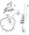
- Figures 1 and 2 show an embodiment the invention, as for example in a device according to DE-U-296 13 336.1 can be used.
- the transmission comprises a cam member 1 and an engagement member 2.
- the cam member 1 is a Shaft 3 driven and has the shape of a bead cam with a bead 4.
- the side walls of the bead 4 form the inner and outer curve flanks 5 and 6.
- the engagement member 2 is about an axis 8 pivotable and has two rollers 9, 10 made of steel, of one on the inner flank 5, the other on the outer curve flank 6 runs. The distance between the two roles is firm. The course of the curve flanks is chosen so that the rollers 9, 10 in all gear positions a game of a few hundredths of a millimeter exhibit.
- the rotation of the cam member 1 causes one Pivotal movement of the engaging member 2, e.g. on a Tool 12 can be passed on.
- a pressure rib 13 is arranged along the outer edge of the outer curve flank 6 . This extends around the entire circumference of the curve flank 6. It is from a Rubber body formed, which lies in a recess 14. The recess 14 has typical edge lengths of 3 mm and the pressure rib 13 projects beyond the curve flank 6 Height T of about 0.5 mm.
- the pressure rib 13 achieves that roller 10 is constantly in frictional contact with the cam member 1 even if the force of the engaging member 2 is e.g. acts from the side of the other roller 9.
- Roll 9 also has thanks to the pressure rib 13 better contact to the curve member 1, since the pressure rib 13, the roller 10 from the outer Edge 6 of the curve is pushed away and thus the roller 9 presses against the inner curve flank 5.
- the pressure rib 13 is formed by a rubber body. Rubber is used as a material preferred because it is elastic and has a high coefficient of friction having.
- the pressure rib 13 also along concave curve areas nestled on the curve flank, it should be held firmly in the recess 14.
- vulcanizing the rubber into the recess 14 is.
- a contour shape is used during manufacture 18 placed over the bead 4, as shown in FIG. 5 you can see.
- Rubber material introduced and vulcanized. After that the contour shape 18 removed.
- This simple way of making is possible because the recess 14 on the edge of the Flank 6 is arranged and is open on two sides.
- a pressure rib 13 as described above can can also be used in other cam mechanisms a reliable frictional connection between the curve flank and Grant role. So this construction is also special suitable for grooved cams to the in the groove to drive running roller for rotation.
Landscapes
- Engineering & Computer Science (AREA)
- General Engineering & Computer Science (AREA)
- Mechanical Engineering (AREA)
- Transmission Devices (AREA)
- Valve-Gear Or Valve Arrangements (AREA)
- Valve Device For Special Equipments (AREA)
- Gears, Cams (AREA)
- Rolls And Other Rotary Bodies (AREA)
Abstract
Description
Claims (9)
- Kurvengetriebe mit einem Kurvenglied (1) mit mindestens einer Kurvenflanke (5, 6) und mit einem Eingriffsglied (2) mit mindestens einer auf der Kurvenflanke rollenden Rolle (9, 10), gekennzeichnet durch mindestens eine Druckrippe (13), die sich mindestens über einen Teil des Umfangs der Kurvenflanke (6) erstreckt, und die von der auf der Kurvenflanke rollenden Rolle (10) elastisch verformbar ist.
- Kurvengetriebe nach Anspruch 1, dadurch gekennzeichnet, dass die Kurvenflanke aus Metall und die Druckrippe (13) aus Kunststoff ist.
- Kurvengetriebe nach einem der vorangehenden Ansprüche, dadurch gekennzeichnet, dass die Druckrippe (13) mindestens teilweise aus Gummi ist.
- Kurvengetriebe nach einem der vorangehenden Ansprüche, dadurch gekennzeichnet, dass die Druckrippe (13) von einem länglichen Körper gebildet ist, der von einer sich entlang der Kurvenflanke (6) erstreckenden Vertiefung (14) gehalten ist und in unverformtem Zustand über die Kurvenflanke (6) heraussteht.
- Kurvengetriebe nach Anspruch 4, dadurch gekennzeichnet, dass der längliche Körper ein in die Vertiefung (14) einvulkanisierter Gummi ist.
- Kurvengetriebe nach einem der Ansprüche 4 oder 5, dadurch gekennzeichnet, dass die Vertiefung (14) in einem Randbereich der Kurvenflanke (6) verläuft, derart, dass sie nach zwei Seiten offen ist.
- Kurvengetriebe nach einem der vorangehenden Ansprüche, dadurch gekennzeichnet, dass das Kurvenglied eine Kurvenwulst (4) oder Kurvennut aufweist, von welcher das Eingriffsglied (2) zweiseitig geführt ist, wobei die mindestens eine Druckrippe (13) derart dimensioniert ist, dass die Rolle bzw. Rollen (9, 10) in allen Stellungen in Reibschluss mit dem Kurvenglied (1) stehen.
- Kurvengetriebe nach Anspruch 7, dadurch gekennzeichnet, dass das Kurvenglied eine Kurvenwulst (4) aufweist.
- Kurvengetriebe nach einem der Ansprüche 7 oder 8, dadurch gekennzeichnet, dass an beiden Kurvenflanken der Kurvenwulst (4) bzw. Kurvennut eine Druckrippe (13) angeordnet ist.
Applications Claiming Priority (2)
| Application Number | Priority Date | Filing Date | Title |
|---|---|---|---|
| DE29802343U | 1998-02-11 | ||
| DE29802343U DE29802343U1 (de) | 1998-02-11 | 1998-02-11 | Kurvengetriebe |
Publications (3)
| Publication Number | Publication Date |
|---|---|
| EP0935920A2 true EP0935920A2 (de) | 1999-08-18 |
| EP0935920A3 EP0935920A3 (de) | 2001-09-05 |
| EP0935920B1 EP0935920B1 (de) | 2003-11-19 |
Family
ID=8052520
Family Applications (1)
| Application Number | Title | Priority Date | Filing Date |
|---|---|---|---|
| EP99102431A Expired - Lifetime EP0935920B1 (de) | 1998-02-11 | 1999-02-09 | Kurvengetriebe |
Country Status (4)
| Country | Link |
|---|---|
| EP (1) | EP0935920B1 (de) |
| AT (1) | ATE254733T1 (de) |
| DE (2) | DE29802343U1 (de) |
| ES (1) | ES2209254T3 (de) |
Cited By (2)
| Publication number | Priority date | Publication date | Assignee | Title |
|---|---|---|---|---|
| FR2833330A1 (fr) * | 2001-12-12 | 2003-06-13 | Sidel Sa | Dispositif de guidage a came et installation de moulage en faisant application |
| EA031885B1 (ru) * | 2016-09-02 | 2019-03-29 | Общество с ограниченной ответственностью "Машиностроительное предприятие "КОМПО" | Рабочий блок клипсатора |
Families Citing this family (4)
| Publication number | Priority date | Publication date | Assignee | Title |
|---|---|---|---|---|
| DE29802343U1 (de) * | 1998-02-11 | 1998-04-16 | Waelchli Hans | Kurvengetriebe |
| US8511203B2 (en) | 2011-04-07 | 2013-08-20 | Harris Corporation | Compliant cam of composite materials |
| DE102016209431B3 (de) * | 2016-05-31 | 2017-08-03 | Robert Bosch Gmbh | Kupplungsaktuator |
| DE102016209427B3 (de) * | 2016-05-31 | 2017-07-06 | Robert Bosch Gmbh | Kupplungsaktuator |
Citations (1)
| Publication number | Priority date | Publication date | Assignee | Title |
|---|---|---|---|---|
| DE29613336U1 (de) | 1996-08-01 | 1996-09-19 | Tipper Tie Alpina Ag, Gossau | Vorrichtung zum Bilden und Verschließen schlauchförmiger Verpackungen |
Family Cites Families (4)
| Publication number | Priority date | Publication date | Assignee | Title |
|---|---|---|---|---|
| FR2339111A1 (fr) * | 1976-01-26 | 1977-08-19 | Goodrich Co B F | Element de guidage composite |
| JPH04285122A (ja) * | 1991-03-15 | 1992-10-09 | Brother Ind Ltd | カム |
| JPH08144717A (ja) * | 1994-11-16 | 1996-06-04 | Isuzu Motors Ltd | カム装置 |
| DE29802343U1 (de) * | 1998-02-11 | 1998-04-16 | Waelchli Hans | Kurvengetriebe |
-
1998
- 1998-02-11 DE DE29802343U patent/DE29802343U1/de not_active Expired - Lifetime
-
1999
- 1999-02-09 EP EP99102431A patent/EP0935920B1/de not_active Expired - Lifetime
- 1999-02-09 DE DE59907758T patent/DE59907758D1/de not_active Expired - Lifetime
- 1999-02-09 ES ES99102431T patent/ES2209254T3/es not_active Expired - Lifetime
- 1999-02-09 AT AT99102431T patent/ATE254733T1/de active
Patent Citations (1)
| Publication number | Priority date | Publication date | Assignee | Title |
|---|---|---|---|---|
| DE29613336U1 (de) | 1996-08-01 | 1996-09-19 | Tipper Tie Alpina Ag, Gossau | Vorrichtung zum Bilden und Verschließen schlauchförmiger Verpackungen |
Cited By (4)
| Publication number | Priority date | Publication date | Assignee | Title |
|---|---|---|---|---|
| FR2833330A1 (fr) * | 2001-12-12 | 2003-06-13 | Sidel Sa | Dispositif de guidage a came et installation de moulage en faisant application |
| WO2003050438A1 (fr) * | 2001-12-12 | 2003-06-19 | Sidel | Dispositif de guidage a came et installation de moulage en faisant application |
| US7140871B2 (en) | 2001-12-12 | 2006-11-28 | Sidel | Cam-type guiding device and molding installation using same |
| EA031885B1 (ru) * | 2016-09-02 | 2019-03-29 | Общество с ограниченной ответственностью "Машиностроительное предприятие "КОМПО" | Рабочий блок клипсатора |
Also Published As
| Publication number | Publication date |
|---|---|
| ES2209254T3 (es) | 2004-06-16 |
| DE59907758D1 (de) | 2003-12-24 |
| ATE254733T1 (de) | 2003-12-15 |
| EP0935920B1 (de) | 2003-11-19 |
| DE29802343U1 (de) | 1998-04-16 |
| EP0935920A3 (de) | 2001-09-05 |
Similar Documents
| Publication | Publication Date | Title |
|---|---|---|
| DE19730749C2 (de) | Vorrichtung zum Verhindern des Wanderns eines Wälzlagers | |
| DE904720C (de) | Geschlitzte Ausfuetterungsstahlhuelse mit grosser Federkraft und Verschleissfestigkeit | |
| DE2831201A1 (de) | Vorrichtung zum verstellen zweier beweglicher teile zueinander unter ausgleich des zwischen den teilen bestehenden spiels | |
| DE10083638B4 (de) | Laschenkette | |
| DE3732223A1 (de) | Presspassungsaufbau fuer eine rotorwelle | |
| EP3022356B1 (de) | Saug- oder blaswalze mit einer dichtleiste | |
| CH678592A5 (de) | ||
| WO2024188559A1 (de) | Pneumatische klemm- und/oder bremsvorrichtung | |
| WO2024188534A1 (de) | Gehäuseteil für eine pneumatische klemm- und/oder bremsvorrichtung | |
| EP0935920B1 (de) | Kurvengetriebe | |
| DE3330204C2 (de) | Stirnradgetriebe für den Antrieb eines Walzenmantels | |
| EP1430232A1 (de) | Scheibenbremse, insbesondere für ein nutzfahrzeug | |
| EP2995826B2 (de) | Schwenklager | |
| EP1858782A1 (de) | Fördervorrichtung, rollenkörper und förderkörper | |
| DE3619648C2 (de) | ||
| AT403951B (de) | Riemenscheibe für ein synchronantriebssystem | |
| EP3354922A1 (de) | Synchronisiervorrichtung und synchronisationsverfahren | |
| EP0222416B1 (de) | Einspannlagerbuchse | |
| DE2061101B2 (de) | Kugelschraubtrieb | |
| DE2157373A1 (de) | Selbsthaltendes Befestigungselement und Werkzeug zu seiner Herstellung | |
| EP0900952B1 (de) | Riementrieb | |
| DE102007056858B4 (de) | Zweiteiliges Rückführrohr für ein Linearwälzlager | |
| EP4431229A1 (de) | Pneumatische klemm- und/oder bremsvorrichtung | |
| EP4431228A1 (de) | Gehäuseteil für eine pneumatische klemm- und/oder bremsvorrichtung | |
| EP1818240A1 (de) | Druckstück für ein Lenkgetriebe |
Legal Events
| Date | Code | Title | Description |
|---|---|---|---|
| PUAI | Public reference made under article 153(3) epc to a published international application that has entered the european phase |
Free format text: ORIGINAL CODE: 0009012 |
|
| AK | Designated contracting states |
Kind code of ref document: A2 Designated state(s): AT BE CH CY DE DK ES FI FR GB GR IE IT LI LU MC NL PT SE |
|
| AX | Request for extension of the european patent |
Free format text: AL;LT;LV;MK;RO;SI |
|
| RAP1 | Party data changed (applicant data changed or rights of an application transferred) |
Owner name: TIPPER TIE ALPINA AG |
|
| RIN1 | Information on inventor provided before grant (corrected) |
Inventor name: WAELCHLI, HANS DR. |
|
| PUAL | Search report despatched |
Free format text: ORIGINAL CODE: 0009013 |
|
| AK | Designated contracting states |
Kind code of ref document: A3 Designated state(s): AT BE CH CY DE DK ES FI FR GB GR IE IT LI LU MC NL PT SE |
|
| AX | Request for extension of the european patent |
Free format text: AL;LT;LV;MK;RO;SI |
|
| RIC1 | Information provided on ipc code assigned before grant |
Free format text: 7F 16H 25/16 A, 7F 16H 53/06 B, 7A 22C 11/12 B |
|
| 17P | Request for examination filed |
Effective date: 20020304 |
|
| AKX | Designation fees paid |
Free format text: AT BE CH CY DE DK ES FI FR GB GR IE IT LI LU MC NL PT SE |
|
| GRAH | Despatch of communication of intention to grant a patent |
Free format text: ORIGINAL CODE: EPIDOS IGRA |
|
| GRAS | Grant fee paid |
Free format text: ORIGINAL CODE: EPIDOSNIGR3 |
|
| RIN1 | Information on inventor provided before grant (corrected) |
Inventor name: SBALZARINI, LINO Inventor name: WAELCHLI, HANS DR. |
|
| GRAA | (expected) grant |
Free format text: ORIGINAL CODE: 0009210 |
|
| AK | Designated contracting states |
Kind code of ref document: B1 Designated state(s): AT BE CH CY DE DK ES FI FR GB GR IE IT LI LU MC NL PT SE |
|
| PG25 | Lapsed in a contracting state [announced via postgrant information from national office to epo] |
Ref country code: NL Free format text: LAPSE BECAUSE OF FAILURE TO SUBMIT A TRANSLATION OF THE DESCRIPTION OR TO PAY THE FEE WITHIN THE PRESCRIBED TIME-LIMIT Effective date: 20031119 Ref country code: IE Free format text: LAPSE BECAUSE OF FAILURE TO SUBMIT A TRANSLATION OF THE DESCRIPTION OR TO PAY THE FEE WITHIN THE PRESCRIBED TIME-LIMIT Effective date: 20031119 Ref country code: GB Free format text: LAPSE BECAUSE OF FAILURE TO SUBMIT A TRANSLATION OF THE DESCRIPTION OR TO PAY THE FEE WITHIN THE PRESCRIBED TIME-LIMIT Effective date: 20031119 Ref country code: FR Free format text: LAPSE BECAUSE OF FAILURE TO SUBMIT A TRANSLATION OF THE DESCRIPTION OR TO PAY THE FEE WITHIN THE PRESCRIBED TIME-LIMIT Effective date: 20031119 Ref country code: FI Free format text: LAPSE BECAUSE OF FAILURE TO SUBMIT A TRANSLATION OF THE DESCRIPTION OR TO PAY THE FEE WITHIN THE PRESCRIBED TIME-LIMIT Effective date: 20031119 Ref country code: CY Free format text: LAPSE BECAUSE OF FAILURE TO SUBMIT A TRANSLATION OF THE DESCRIPTION OR TO PAY THE FEE WITHIN THE PRESCRIBED TIME-LIMIT Effective date: 20031119 |
|
| REG | Reference to a national code |
Ref country code: GB Ref legal event code: FG4D Free format text: NOT ENGLISH |
|
| REG | Reference to a national code |
Ref country code: CH Ref legal event code: NV Representative=s name: DR. SCHNEIDER & PARTNER INTELLECTUAL PROPERTY RIGH Ref country code: CH Ref legal event code: EP |
|
| REF | Corresponds to: |
Ref document number: 59907758 Country of ref document: DE Date of ref document: 20031224 Kind code of ref document: P |
|
| REG | Reference to a national code |
Ref country code: IE Ref legal event code: FG4D Free format text: GERMAN |
|
| PG25 | Lapsed in a contracting state [announced via postgrant information from national office to epo] |
Ref country code: LU Free format text: LAPSE BECAUSE OF NON-PAYMENT OF DUE FEES Effective date: 20040209 |
|
| PG25 | Lapsed in a contracting state [announced via postgrant information from national office to epo] |
Ref country code: SE Free format text: LAPSE BECAUSE OF FAILURE TO SUBMIT A TRANSLATION OF THE DESCRIPTION OR TO PAY THE FEE WITHIN THE PRESCRIBED TIME-LIMIT Effective date: 20040219 Ref country code: GR Free format text: LAPSE BECAUSE OF FAILURE TO SUBMIT A TRANSLATION OF THE DESCRIPTION OR TO PAY THE FEE WITHIN THE PRESCRIBED TIME-LIMIT Effective date: 20040219 Ref country code: DK Free format text: LAPSE BECAUSE OF FAILURE TO SUBMIT A TRANSLATION OF THE DESCRIPTION OR TO PAY THE FEE WITHIN THE PRESCRIBED TIME-LIMIT Effective date: 20040219 |
|
| PG25 | Lapsed in a contracting state [announced via postgrant information from national office to epo] |
Ref country code: MC Free format text: LAPSE BECAUSE OF NON-PAYMENT OF DUE FEES Effective date: 20040228 Ref country code: BE Free format text: LAPSE BECAUSE OF NON-PAYMENT OF DUE FEES Effective date: 20040228 |
|
| NLV1 | Nl: lapsed or annulled due to failure to fulfill the requirements of art. 29p and 29m of the patents act | ||
| GBV | Gb: ep patent (uk) treated as always having been void in accordance with gb section 77(7)/1977 [no translation filed] |
Effective date: 20031119 |
|
| REG | Reference to a national code |
Ref country code: ES Ref legal event code: FG2A Ref document number: 2209254 Country of ref document: ES Kind code of ref document: T3 |
|
| REG | Reference to a national code |
Ref country code: IE Ref legal event code: FD4D |
|
| BERE | Be: lapsed |
Owner name: *TIPPER TIE ALPINA A.G. Effective date: 20040228 |
|
| PLBE | No opposition filed within time limit |
Free format text: ORIGINAL CODE: 0009261 |
|
| STAA | Information on the status of an ep patent application or granted ep patent |
Free format text: STATUS: NO OPPOSITION FILED WITHIN TIME LIMIT |
|
| 26N | No opposition filed |
Effective date: 20040820 |
|
| EN | Fr: translation not filed | ||
| REG | Reference to a national code |
Ref country code: CH Ref legal event code: PFA Owner name: TIPPER TIE ALPINA AG Free format text: TIPPER TIE ALPINA AG#RINGSTRASSE 14#9201 GOSSAU (CH) -TRANSFER TO- TIPPER TIE ALPINA AG#RINGSTRASSE 14#9201 GOSSAU (CH) |
|
| PG25 | Lapsed in a contracting state [announced via postgrant information from national office to epo] |
Ref country code: PT Free format text: LAPSE BECAUSE OF NON-PAYMENT OF DUE FEES Effective date: 20040419 |
|
| PGFP | Annual fee paid to national office [announced via postgrant information from national office to epo] |
Ref country code: IT Payment date: 20120224 Year of fee payment: 14 |
|
| PGFP | Annual fee paid to national office [announced via postgrant information from national office to epo] |
Ref country code: DE Payment date: 20130219 Year of fee payment: 15 Ref country code: CH Payment date: 20130131 Year of fee payment: 15 Ref country code: ES Payment date: 20130227 Year of fee payment: 15 |
|
| PGFP | Annual fee paid to national office [announced via postgrant information from national office to epo] |
Ref country code: AT Payment date: 20130213 Year of fee payment: 15 |
|
| REG | Reference to a national code |
Ref country code: DE Ref legal event code: R119 Ref document number: 59907758 Country of ref document: DE |
|
| REG | Reference to a national code |
Ref country code: CH Ref legal event code: PL |
|
| REG | Reference to a national code |
Ref country code: AT Ref legal event code: MM01 Ref document number: 254733 Country of ref document: AT Kind code of ref document: T Effective date: 20140209 |
|
| PG25 | Lapsed in a contracting state [announced via postgrant information from national office to epo] |
Ref country code: LI Free format text: LAPSE BECAUSE OF NON-PAYMENT OF DUE FEES Effective date: 20140228 Ref country code: CH Free format text: LAPSE BECAUSE OF NON-PAYMENT OF DUE FEES Effective date: 20140228 |
|
| PG25 | Lapsed in a contracting state [announced via postgrant information from national office to epo] |
Ref country code: AT Free format text: LAPSE BECAUSE OF NON-PAYMENT OF DUE FEES Effective date: 20140209 |
|
| REG | Reference to a national code |
Ref country code: DE Ref legal event code: R119 Ref document number: 59907758 Country of ref document: DE Effective date: 20140902 |
|
| PG25 | Lapsed in a contracting state [announced via postgrant information from national office to epo] |
Ref country code: DE Free format text: LAPSE BECAUSE OF NON-PAYMENT OF DUE FEES Effective date: 20140902 |
|
| REG | Reference to a national code |
Ref country code: ES Ref legal event code: FD2A Effective date: 20150408 |
|
| PG25 | Lapsed in a contracting state [announced via postgrant information from national office to epo] |
Ref country code: ES Free format text: LAPSE BECAUSE OF NON-PAYMENT OF DUE FEES Effective date: 20140210 |
|
| PG25 | Lapsed in a contracting state [announced via postgrant information from national office to epo] |
Ref country code: IT Free format text: LAPSE BECAUSE OF NON-PAYMENT OF DUE FEES Effective date: 20140209 |