EP0936009A1 - Dispositif de valve, notament dispositif de valve pour évacuation pour couler sous pression - Google Patents
Dispositif de valve, notament dispositif de valve pour évacuation pour couler sous pression Download PDFInfo
- Publication number
- EP0936009A1 EP0936009A1 EP98810107A EP98810107A EP0936009A1 EP 0936009 A1 EP0936009 A1 EP 0936009A1 EP 98810107 A EP98810107 A EP 98810107A EP 98810107 A EP98810107 A EP 98810107A EP 0936009 A1 EP0936009 A1 EP 0936009A1
- Authority
- EP
- European Patent Office
- Prior art keywords
- valve
- control
- piston
- vent
- pressure
- Prior art date
- Legal status (The legal status is an assumption and is not a legal conclusion. Google has not performed a legal analysis and makes no representation as to the accuracy of the status listed.)
- Granted
Links
- 238000004512 die casting Methods 0.000 title claims description 24
- 238000013022 venting Methods 0.000 title claims description 3
- 239000007789 gas Substances 0.000 claims description 5
- 238000009423 ventilation Methods 0.000 abstract description 5
- 238000005266 casting Methods 0.000 description 9
- 239000002184 metal Substances 0.000 description 6
- 238000000034 method Methods 0.000 description 4
- 229910001338 liquidmetal Inorganic materials 0.000 description 3
- 238000001746 injection moulding Methods 0.000 description 2
- 239000007788 liquid Substances 0.000 description 2
- 239000000463 material Substances 0.000 description 2
- 230000006978 adaptation Effects 0.000 description 1
- 238000006243 chemical reaction Methods 0.000 description 1
- 230000006735 deficit Effects 0.000 description 1
- 230000003111 delayed effect Effects 0.000 description 1
- 238000000605 extraction Methods 0.000 description 1
- 238000005429 filling process Methods 0.000 description 1
- 238000002347 injection Methods 0.000 description 1
- 239000007924 injection Substances 0.000 description 1
- 238000003780 insertion Methods 0.000 description 1
- 230000037431 insertion Effects 0.000 description 1
- 238000012423 maintenance Methods 0.000 description 1
- 238000003825 pressing Methods 0.000 description 1
- 230000002787 reinforcement Effects 0.000 description 1
- 238000007789 sealing Methods 0.000 description 1
- 238000013519 translation Methods 0.000 description 1
Images
Classifications
-
- B—PERFORMING OPERATIONS; TRANSPORTING
- B22—CASTING; POWDER METALLURGY
- B22D—CASTING OF METALS; CASTING OF OTHER SUBSTANCES BY THE SAME PROCESSES OR DEVICES
- B22D17/00—Pressure die casting or injection die casting, i.e. casting in which the metal is forced into a mould under high pressure
- B22D17/14—Machines with evacuated die cavity
- B22D17/145—Venting means therefor
Definitions
- the present invention relates to a Valve device, in particular on a vent valve device for die casting according to the generic term of Claim 1.
- vent valve devices for the Die casting are by Metal actuation actuated by the device Has force transducer on which the casting material acts, the force transducer with the movable closure part of the vent valve is in mechanical operative connection.
- the closing times achieved are very fast, which makes it possible even in the high speed printing area to work, but it is disadvantageous that liquid due to the necessary control stroke of the force transducer Metal in every insertion stroke, also in its guide bore penetrates. This leads to wear on the control piston as well in its guide hole. Cold welds are also on these places known to block the spool being able to lead.
- DE-A-39 12 006 is a gas extraction device with a high-speed injection molding device known in which a gas discharge control valve by a Combination of a control circuit with a Valve drive device at high speed can be closed.
- This device from which in The preamble of claim 1 is assumed, includes a relatively complex control circuit, wherein the actual control valves through servo valves be controlled in order to achieve fast switching times. The actual control signals have to be amplified converted and adapted to existing interfaces become.
- DE-A-42 16 773 is a die-casting device known, wherein the triggering device in the metal sensor engaging the pouring barrel with a subsequent one Has switching device, the valve being delayed is closed.
- a valve device in this regard to improve that no mechanical influences quick closing process even during long periods of operation can affect.
- a device should be possible have few components and clear switching positions.
- the Control should be simple and without servo valves get along, d. H. can be controlled directly.
- the control signal to close the vent valve should be without Reinforcement, conversion and adaptation to any Interfaces get along, also directly for control be suitable. It is important that the real Closing process of the valve device in just a few Milliseconds is complete, d. H. the closing time Such a vent valve should close the closing time metal-loaded valve not or only insignificantly inferior.
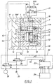
- valve 1 shows the two valve blocks 1 and 2, the vent duct plate 3 with the first Vent hole 5, the second vent hole 4 and the third vent hole 9 and between the Valve block 1 and the ventilation duct plate 3 extending Vent channel 6.
- the parting surface of the die-casting mold between the ventilation duct plate 3 and the valve block 1 is indicated with TRF.
- the functional part of the vent valve device contains the control piston 7, which has a first Driving pin 11 is connected to a lever 15 which is hinged at one end to a bearing pin 12 and at the other end via a second driver pin 11A the suction piston 8 is articulated, which in the first Vent hole 5 is performed to complete this.
- the lever 15 or the bearing pin 12 is in a bearing block 16 mounted and the control piston 7 is in the valve block 1 and guided in a guide 10.
- the mold insert 13 of the fixed mold half can also be seen and the mold insert 14 of the movable mold half and the mold frame 18 of the fixed mold half and the mold frame 17 of the movable mold half.
- Controlling the closing movement of the suction piston 8 takes place via the control piston 7, which via a direct controllable high-response valve (HR valve) without additional electronic gain is controlled.
- HR valve high-response valve
- Such Valves are especially low-mass, heat-resistant and very powerful with extremely short switching times.
- the HR valve 21 is connected to a pressure line 40 which is connected by a Pressure source 25 is supplied, the output of the Pressure line of this valve connected to the control piston 7 and on the first pressure surface F1 to actuate the Control piston acts and thus to open the suction piston 8 serves.
- the HR valve 21 has a vent 21R, wherein the cross section of the vent line 41 at least twice is as large as the cross section of the pressure line 42 and is as short as possible to make a very quick one Pressure drop in the pressure line to the control piston cause. From Figure 1 also shows that the HR valve 21 is attached directly to the valve block.
- the control piston 7 is also via a second control valve 20 connected to a second pressure line 42, which with the first pressure line 40 via the second control valve 20 can be connected, the pressure line 42 to the second button F2 acts to control spool 7 in To move the closing direction and thus the suction piston 8 conclude.
- the control piston 7 is therefore a double-acting Pneumatic cylinder, with the second control valve 20 immediately “suction" of the control piston 7 in Closing direction is loaded, d. H. the pneumatic pressure is before the actual control signal to close the Valve on both sides of the double-acting spool on.
- the venting of the HR valve is controlled via vent line 41 and thereby caused sudden pressure drop in the pressure line 40 between the HR valve and pressure area F1 the fastest possible response as well as switching time given the closing movement perform.
- the lever 15 acts as a translation the suction piston 8 to be closed to the control stroke of the Keep the spool as small as possible. Out of it there is a fastest possible control stroke on the control piston 7, that can be covered in no time at all Close the suction piston 8.
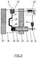
- the number 22 is the actual control circuit specified, in which one next to the already mentioned second Control valve 20 that is connected to the vacuum source 26 Vacuum valve 19 and the so-called PLC control 23 recognizes PLC for programmable logic controller stands.
- the PLC controller 23 is in this example with the Die-casting machine control 24 connected, but can also be connected to an external auxiliary control.
- the Vent valve device is schematic in one Unit 27 summarized, the HR valve 21st is included and the vent hole 9 and the Vent channel 6 can be seen as well as the PLC control 23.
- This PLC controller 23 is with a signal generator "Vacuum stop” 34 connected, which in turn with the signal trigger "Vacuum stop” 33 is operatively connected.
- the switching point Vakustop 33 is located on the casting or press-in piston 32, which is guided in the casting chamber 31.
- the fixed die half 35 and the movable die half 36 and the Die-casting machine plates 37 are shown.
- the ventilation duct 6 the mold cavity 28 and the sprue channel 29 close which, after the filling process, with the pressing residue 30 connected is.
- Such a latest generation can be used as a PLC control used in the normal program flow with Program steps of approximately 30 milliseconds works and at which is the control command to control the HR valve from normal program flow can be excluded so that this special control function in less than one Millisecond can be executed.
- the controls work with a normal operating voltage of 24 volts Direct current.
- the HR valve 21 is digital Logic.
- the operation of the vent valve device is following: At the start of pouring there is a maximum pressure of 8 bar on the pressure surface F1 of the double-acting control piston 7 on.
- the die casting mold is open and the last casting is has been expelled via the pressure at F1.
- the die casting mold is closed by the die casting machine, the liquid one Metal is poured into the casting chamber 31 and the Die-casting machine control 24 gives the cycle start for the Press-in process free.
- a delay of for example, 0.5 seconds will evacuate the air and Gases from the die casting mold, casting barrels and casting chamber from the die casting machine control 24 via input A and Output A 'started and the vacuum valve 19 opens.
- the Air and the gases in the die are over the Vent holes 4, 5 and 9 as well as over the Vent channel 6, which the vent valve with the Mold cavity 28 connects the die, through which Vacuum source 26 is drawn off and passed into a vacuum tank.
- the second control valve 20 directly from the PLC control 23 or via input B and output B ' started and opened, the pressure at F2 increases to maximum 8 bar and the control piston is charged.
- the press-in piston 32 is propelled at high speed until it hits the press rest 30.
- the HR valve Opens after the control signal is received the HR valve from 0 to 100% in less than two Milliseconds and vented through the 21R outlet.
- the pressure on the first cylinder surface F1 drops very much quickly together and the control piston 7 presses the Suction piston 8 by the already existing pressure of maximum 8 bar on the cylinder surface F2 of the control piston 7 in the sealing hole of the first vent hole 5 um to complete this.
- the control piston 7 acts over the driver pin 11, the control piston 7, the lever 15th and couple the suction piston 8 together and together over the bearing pin 12 and the bearing block 16 a Form locking device.
- a ratio of 1: 3 was selected for the lever 15. This ratio can also be different, for example 1: 2 to 1: 5.
- the HR valve 21 returns to the position via C ' normally open "and restores the pressure on the surface F1 for pushing or opening the vent valve or the suction piston 8.
- the control valves 19 and 20 go to theirs Home position back and the pressure at F2 drops to 0 bar off, the suction piston 8 can be opened. Is mechanical the control stroke limitation in the closing direction of the Vent valve by simultaneously hitting the Control piston 7 and the suction piston 8 on the valve block 2 given. The suction piston 8 closes the Vent hole 5 flush to vent channel 6, so no liquid metal in the vent hole 5 of the Valve block 1 can penetrate.
- the control stroke limitation in the opening direction of the Suction piston 8 is given by the control piston 7, which on Valve block 1 is pending.
- the precisely defined keeping of the Suction piston, d. H. of the entire vent valve with the same and simultaneous pressure on the Differential areas F1 and F2 of the control piston 7, which is also called Differential pistons can be given.
- the printing area F1 i.e. H. opening side, larger than the printing area F2, for example in a ratio of 2: 1.
- the switching point for the Control signal depending on the speed of the plunger can be set.
- the goal is a fixed switching point that regardless of press-in piston speed, size of the Die casting mold or the die casting machine is. You can Piston speeds up to seven meters / second occurrence. This results in a fixed switching point for the Signal trigger Vakustop 33, for example 42 mm in front of the Press rest can lie.
- the control signal to HR valve 21 could also be from others Sources come, for example, from the die casting machine control system 24, from other metal sensors or Pressure sensors, acoustic detectors or thermal sensors or other electronic contacts. This is through the Flexibility of the PLC control 23 used possible.
- the vent valve device has been associated with described a high-speed die casting device, but it is possible to use such a valve device for to use other pouring devices, e.g. B. for Low pressure casting or injection molding.
Landscapes
- Engineering & Computer Science (AREA)
- Mechanical Engineering (AREA)
- Moulds For Moulding Plastics Or The Like (AREA)
- Molds, Cores, And Manufacturing Methods Thereof (AREA)
- Injection Moulding Of Plastics Or The Like (AREA)
Priority Applications (5)
| Application Number | Priority Date | Filing Date | Title |
|---|---|---|---|
| ES98810107T ES2198677T3 (es) | 1998-02-11 | 1998-02-11 | Dispositivo de valvulas, sobre todo un dispositivo de valvulas de escape de aire para la fundicion a presion. |
| DE59808448T DE59808448D1 (de) | 1998-02-11 | 1998-02-11 | Ventilvorrichtung, insbesondere Entlüftungsventil-Vorrichtung für den Druckguss |
| AT98810107T ATE240808T1 (de) | 1998-02-11 | 1998-02-11 | Ventilvorrichtung, insbesondere entlüftungsventil-vorrichtung für den druckguss |
| EP98810107A EP0936009B1 (fr) | 1998-02-11 | 1998-02-11 | Dispositif de soupape, notamment pour l'évacuation du moule en coulée sous pression |
| US09/220,852 US6158495A (en) | 1998-02-11 | 1998-12-28 | Venting valve device for die casting |
Applications Claiming Priority (1)
| Application Number | Priority Date | Filing Date | Title |
|---|---|---|---|
| EP98810107A EP0936009B1 (fr) | 1998-02-11 | 1998-02-11 | Dispositif de soupape, notamment pour l'évacuation du moule en coulée sous pression |
Publications (2)
| Publication Number | Publication Date |
|---|---|
| EP0936009A1 true EP0936009A1 (fr) | 1999-08-18 |
| EP0936009B1 EP0936009B1 (fr) | 2003-05-21 |
Family
ID=8235932
Family Applications (1)
| Application Number | Title | Priority Date | Filing Date |
|---|---|---|---|
| EP98810107A Expired - Lifetime EP0936009B1 (fr) | 1998-02-11 | 1998-02-11 | Dispositif de soupape, notamment pour l'évacuation du moule en coulée sous pression |
Country Status (5)
| Country | Link |
|---|---|
| US (1) | US6158495A (fr) |
| EP (1) | EP0936009B1 (fr) |
| AT (1) | ATE240808T1 (fr) |
| DE (1) | DE59808448D1 (fr) |
| ES (1) | ES2198677T3 (fr) |
Cited By (6)
| Publication number | Priority date | Publication date | Assignee | Title |
|---|---|---|---|---|
| DE19952116A1 (de) * | 1999-10-29 | 2001-05-17 | Audi Ag | Verfahren zum Betreiben eienr Druckgießmaschine und Druckgießmaschien zur Durchführung des Verfahrens sowie Verfahren zur Beschichtung von in einem Druckgießverfahren hergestellten Gussstücken |
| EP1190790A1 (fr) * | 2000-09-22 | 2002-03-27 | V.D.S. Vacuum Diecasting Service SA | Soupape d'évacuation pour machine de coulée sous pression |
| WO2003022489A3 (fr) * | 2001-09-12 | 2003-08-07 | Alcan Bdw Gmbh & Co Kg | Procede de commande d'une soupape a vide d'un dispositif de moulage sous vide et dispositif de moulage sous vide |
| WO2012168841A2 (fr) | 2011-06-09 | 2012-12-13 | V.D.S. Vacuum Diecasting Service S.A. | Dispositif de vanne d'aspiration pour l'évacuation de gaz d'un moule |
| CN108253181A (zh) * | 2018-01-12 | 2018-07-06 | 江苏远洋阀门智控股份有限公司 | 一种真空截止阀 |
| CN108480596A (zh) * | 2018-05-22 | 2018-09-04 | 宁波北仑益鸣企业管理服务有限公司 | 一种用于压铸模具的真空阀抽气装置 |
Families Citing this family (8)
| Publication number | Priority date | Publication date | Assignee | Title |
|---|---|---|---|---|
| JP2002166448A (ja) * | 2000-12-01 | 2002-06-11 | Sony Corp | 成形用金型装置および成形方法 |
| EP1295655B1 (fr) * | 2001-09-21 | 2006-10-25 | Fondarex S.A. | Dispositif de soupape pour l'évacuation des moules de fonderrie |
| DE202010009221U1 (de) * | 2010-06-17 | 2011-09-07 | Electronics Gmbh | Vakuumblock mit Unterdruckzylinderfunktion |
| US8863817B2 (en) * | 2011-06-30 | 2014-10-21 | United Technologies Corporation | System and method for high temperature die casting tooling |
| CN102794430B (zh) * | 2011-08-29 | 2015-11-18 | 日本模具贸易株式会社 | 一种压铸模用排气装置 |
| CH710347B1 (de) * | 2014-11-07 | 2018-05-31 | Fondarex Sa | Ventileinrichtung zum Entlüften von Druckgiessformen. |
| ES2631502B1 (es) * | 2016-09-06 | 2018-06-05 | Comercial Nicem-Exinte, S.A - Coniex | Equipo de inyección de metal en molde polimérico, molde polimérico utilizado y procedimiento de funcionamiento del conjunto |
| JP7068880B2 (ja) * | 2018-03-26 | 2022-05-17 | 本田技研工業株式会社 | 減圧遮断弁装置及びその制御方法 |
Citations (3)
| Publication number | Priority date | Publication date | Assignee | Title |
|---|---|---|---|---|
| DE3912006A1 (de) * | 1988-05-16 | 1989-11-30 | Ryobi Ltd | Gasabzugsvorrichtung bei einer hochgeschwindigkeits-spritzgiessvorrichtung und verfahren zum gasabzug bei der hochgeschwindigkeits-spritzgiessvorrichtung |
| DE4216773A1 (de) * | 1992-05-21 | 1993-11-25 | Kurt Loeffler Druckgus Gmbh & | Druckgußvorrichtung |
| DE4302798C1 (de) * | 1993-02-02 | 1994-06-16 | Hodler F & Cie Fondarex Sa | Ventileinrichtung zum Entlüften von Druckgiessformen |
Family Cites Families (6)
| Publication number | Priority date | Publication date | Assignee | Title |
|---|---|---|---|---|
| DE2751431C2 (de) * | 1977-11-17 | 1986-03-06 | Fritz Territet Vaud Hodler | Entlüftungsventil für Druckgießformen |
| DE3002886A1 (de) * | 1980-01-28 | 1981-07-30 | Bayrisches Druckguß-Werk Thurner KG, 8015 Markt Schwaben | Druckgiessmaschine und verfahren zum betrieb derselben |
| JPS63256252A (ja) * | 1987-04-10 | 1988-10-24 | Aisan Ind Co Ltd | 金型のガス抜き装置 |
| JPS6427757A (en) * | 1987-07-22 | 1989-01-30 | Aisin Seiki | Gas venting device in die for die casting |
| JP2572462B2 (ja) * | 1989-11-17 | 1997-01-16 | 東洋機械金属株式会社 | 真空ダイカストマシン |
| JPH08243716A (ja) * | 1995-03-09 | 1996-09-24 | Showa:Kk | 金型のガス抜き装置 |
-
1998
- 1998-02-11 DE DE59808448T patent/DE59808448D1/de not_active Expired - Lifetime
- 1998-02-11 ES ES98810107T patent/ES2198677T3/es not_active Expired - Lifetime
- 1998-02-11 AT AT98810107T patent/ATE240808T1/de active
- 1998-02-11 EP EP98810107A patent/EP0936009B1/fr not_active Expired - Lifetime
- 1998-12-28 US US09/220,852 patent/US6158495A/en not_active Expired - Lifetime
Patent Citations (3)
| Publication number | Priority date | Publication date | Assignee | Title |
|---|---|---|---|---|
| DE3912006A1 (de) * | 1988-05-16 | 1989-11-30 | Ryobi Ltd | Gasabzugsvorrichtung bei einer hochgeschwindigkeits-spritzgiessvorrichtung und verfahren zum gasabzug bei der hochgeschwindigkeits-spritzgiessvorrichtung |
| DE4216773A1 (de) * | 1992-05-21 | 1993-11-25 | Kurt Loeffler Druckgus Gmbh & | Druckgußvorrichtung |
| DE4302798C1 (de) * | 1993-02-02 | 1994-06-16 | Hodler F & Cie Fondarex Sa | Ventileinrichtung zum Entlüften von Druckgiessformen |
Cited By (13)
| Publication number | Priority date | Publication date | Assignee | Title |
|---|---|---|---|---|
| DE19952116A1 (de) * | 1999-10-29 | 2001-05-17 | Audi Ag | Verfahren zum Betreiben eienr Druckgießmaschine und Druckgießmaschien zur Durchführung des Verfahrens sowie Verfahren zur Beschichtung von in einem Druckgießverfahren hergestellten Gussstücken |
| DE19952116B4 (de) * | 1999-10-29 | 2006-09-28 | Audi Ag | Verwendung eines Metall-Druckgussstückes, hergestellt durch Vakuumgießen |
| EP1190790A1 (fr) * | 2000-09-22 | 2002-03-27 | V.D.S. Vacuum Diecasting Service SA | Soupape d'évacuation pour machine de coulée sous pression |
| KR100849255B1 (ko) * | 2000-09-22 | 2008-07-29 | 브이.디.에스. 배큠 다이케스팅 서비스 에스에이 | 다이캐스팅 밸브 |
| WO2003022489A3 (fr) * | 2001-09-12 | 2003-08-07 | Alcan Bdw Gmbh & Co Kg | Procede de commande d'une soupape a vide d'un dispositif de moulage sous vide et dispositif de moulage sous vide |
| US6948549B2 (en) | 2001-09-12 | 2005-09-27 | Alcan Bdw Gmbh & Co. Kg | Method for controlling a vacuum valve of a vacuum die casting device and a vacuum die casting device |
| WO2012168841A2 (fr) | 2011-06-09 | 2012-12-13 | V.D.S. Vacuum Diecasting Service S.A. | Dispositif de vanne d'aspiration pour l'évacuation de gaz d'un moule |
| CH705077A1 (fr) * | 2011-06-09 | 2012-12-14 | V D S Vacuum Diecasting Service S A | Dispositif de vanne pour l'évacuation d'air d'un moule. |
| WO2012168841A3 (fr) * | 2011-06-09 | 2013-10-24 | V.D.S. Vacuum Diecasting Service S.A. | Dispositif de vanne d'aspiration pour l'évacuation de gaz d'un moule |
| US9050653B2 (en) | 2011-06-09 | 2015-06-09 | V.D.S. Vacuum Diecasting Service S.A. | Suction valve device for discharging gas from a mould |
| CN108253181A (zh) * | 2018-01-12 | 2018-07-06 | 江苏远洋阀门智控股份有限公司 | 一种真空截止阀 |
| CN108480596A (zh) * | 2018-05-22 | 2018-09-04 | 宁波北仑益鸣企业管理服务有限公司 | 一种用于压铸模具的真空阀抽气装置 |
| CN108480596B (zh) * | 2018-05-22 | 2020-03-31 | 宁波北仑益鸣企业管理服务有限公司 | 一种用于压铸模具的真空阀抽气装置 |
Also Published As
| Publication number | Publication date |
|---|---|
| ES2198677T3 (es) | 2004-02-01 |
| US6158495A (en) | 2000-12-12 |
| DE59808448D1 (de) | 2003-06-26 |
| ATE240808T1 (de) | 2003-06-15 |
| EP0936009B1 (fr) | 2003-05-21 |
Similar Documents
| Publication | Publication Date | Title |
|---|---|---|
| EP0936009B1 (fr) | Dispositif de soupape, notamment pour l'évacuation du moule en coulée sous pression | |
| DE69201769T2 (de) | Hydraulische Polsteranordnung für eine Presse, mit einem Absperrventil zum Abschalten der Energieversorgung der Druckbolzen beim Kontakt des beweglichen Werkzeugs mit dem Werkstück. | |
| DE3518635A1 (de) | Druckgussverfahren und -vorrichtung | |
| DE3912006C2 (de) | Gasabzugsvorrichtung bei einer Hochgeschwindigkeits-Druckgießmaschine | |
| EP0462046A2 (fr) | Installation hydraulique sur le dispositif de fermeture pour presse à injection de matières plastiques | |
| EP0937524A1 (fr) | Procédé pour désaérer des moules à couler sous pression et dispositif à valve pour la mise en oeuvre de ce procédé | |
| DE10144945B4 (de) | Verfahren zum Steuern eines Vakuumventils einer Vakuumdruckgießvorrichtung sowie Vakuumdruckgießvorrichtung | |
| EP4281282B1 (fr) | Machine de formage hydraulique destinée à comprimer des pièces, en particulier marteau à forger, et procédé pour faire fonctionner une machine de formage hydraulique, en particulier un marteau à forger | |
| EP1714764A2 (fr) | Unité de fermeture de moule hydraulique | |
| DE19629065A1 (de) | Hydraulische Betätigungsanordnung für ein Fahrzeugverdeck | |
| EP3880975B1 (fr) | Système d'actionneur électrohydrostatique | |
| EP1494844B1 (fr) | Dispositif hydraulique pour actionner d'un mouvement alternatif une piece de machine et unite de fermeture de machine de moulage par injection equipee de ce dispositif hydraulique | |
| DE4313800B4 (de) | Vakuumdruckgussverfahren | |
| EP2280178A1 (fr) | Dispositif et méthode de contôle pour un ensemble piston-cylindre | |
| DE4108220C2 (de) | Kolben-Zylinder-Anordnung | |
| DE2505648B2 (de) | Steuervorrichtung fuer eine einspritzvorrichtung fuer spritzgussmaschinen | |
| EP0616882B1 (fr) | Méthode de commande hydraulique d'une presse à levier articulée ou à genoullière et presse à levier articulée ou à genoullière avec un système de commande adapté à la mise en oeuvre de la méthode | |
| DE3508277A1 (de) | Geraet zur steuerung der bewegung eines kolbens in einem doppeltwirkenden pneumatikzylinder, insbesondere fuer pneumatisch betaetigbare schweisszangen | |
| DE2020290C3 (de) | Vorrichtung zum Steuern des Schließ gestelle einer Hohlkorperblasmaschine | |
| DE3325301A1 (de) | Hydraulische vulkanisierpresse | |
| EP1114918B1 (fr) | Commande de soupape pour moteur à combustion interne et mode d'opération | |
| DE1458151A1 (de) | Spritzgussmaschine | |
| DE202004002221U1 (de) | Multi-Positions-Tandemzylinder für Schweißzangen | |
| DE10208720B4 (de) | Stempelseitige Auswerfvorrichtung für Werkstücke bei Ein- oder Mehrstufenpressen | |
| DE3922212A1 (de) | Regelschaltung fuer den hochlauf der druckwange eines ziehapparats |
Legal Events
| Date | Code | Title | Description |
|---|---|---|---|
| PUAI | Public reference made under article 153(3) epc to a published international application that has entered the european phase |
Free format text: ORIGINAL CODE: 0009012 |
|
| AK | Designated contracting states |
Kind code of ref document: A1 Designated state(s): AT BE CH DE DK ES FI FR GB GR IE IT LI LU MC NL PT SE Kind code of ref document: A1 Designated state(s): AT CH DE ES FR GB IT LI SE |
|
| AX | Request for extension of the european patent |
Free format text: AL;LT;LV;MK;RO;SI |
|
| 17P | Request for examination filed |
Effective date: 19991204 |
|
| AKX | Designation fees paid |
Free format text: AT CH DE ES FR GB IT LI SE |
|
| GRAH | Despatch of communication of intention to grant a patent |
Free format text: ORIGINAL CODE: EPIDOS IGRA |
|
| GRAH | Despatch of communication of intention to grant a patent |
Free format text: ORIGINAL CODE: EPIDOS IGRA |
|
| GRAA | (expected) grant |
Free format text: ORIGINAL CODE: 0009210 |
|
| AK | Designated contracting states |
Designated state(s): AT CH DE ES FR GB IT LI SE |
|
| REG | Reference to a national code |
Ref country code: GB Ref legal event code: FG4D Free format text: NOT ENGLISH |
|
| REG | Reference to a national code |
Ref country code: CH Ref legal event code: NV Representative=s name: AMMANN PATENTANWAELTE AG BERN Ref country code: CH Ref legal event code: EP |
|
| REF | Corresponds to: |
Ref document number: 59808448 Country of ref document: DE Date of ref document: 20030626 Kind code of ref document: P |
|
| GBT | Gb: translation of ep patent filed (gb section 77(6)(a)/1977) | ||
| REG | Reference to a national code |
Ref country code: SE Ref legal event code: TRGR |
|
| REG | Reference to a national code |
Ref country code: ES Ref legal event code: FG2A Ref document number: 2198677 Country of ref document: ES Kind code of ref document: T3 |
|
| ET | Fr: translation filed | ||
| PLBE | No opposition filed within time limit |
Free format text: ORIGINAL CODE: 0009261 |
|
| STAA | Information on the status of an ep patent application or granted ep patent |
Free format text: STATUS: NO OPPOSITION FILED WITHIN TIME LIMIT |
|
| 26N | No opposition filed |
Effective date: 20040224 |
|
| REG | Reference to a national code |
Ref country code: FR Ref legal event code: PLFP Year of fee payment: 19 |
|
| REG | Reference to a national code |
Ref country code: FR Ref legal event code: PLFP Year of fee payment: 20 |
|
| PGFP | Annual fee paid to national office [announced via postgrant information from national office to epo] |
Ref country code: CH Payment date: 20170221 Year of fee payment: 20 Ref country code: SE Payment date: 20170216 Year of fee payment: 20 Ref country code: DE Payment date: 20170217 Year of fee payment: 20 Ref country code: FR Payment date: 20170217 Year of fee payment: 20 |
|
| PGFP | Annual fee paid to national office [announced via postgrant information from national office to epo] |
Ref country code: GB Payment date: 20170216 Year of fee payment: 20 Ref country code: AT Payment date: 20170217 Year of fee payment: 20 |
|
| PGFP | Annual fee paid to national office [announced via postgrant information from national office to epo] |
Ref country code: ES Payment date: 20170213 Year of fee payment: 20 Ref country code: IT Payment date: 20170221 Year of fee payment: 20 |
|
| REG | Reference to a national code |
Ref country code: DE Ref legal event code: R071 Ref document number: 59808448 Country of ref document: DE |
|
| REG | Reference to a national code |
Ref country code: CH Ref legal event code: PL |
|
| REG | Reference to a national code |
Ref country code: GB Ref legal event code: PE20 Expiry date: 20180210 |
|
| REG | Reference to a national code |
Ref country code: AT Ref legal event code: MK07 Ref document number: 240808 Country of ref document: AT Kind code of ref document: T Effective date: 20180211 |
|
| PG25 | Lapsed in a contracting state [announced via postgrant information from national office to epo] |
Ref country code: GB Free format text: LAPSE BECAUSE OF EXPIRATION OF PROTECTION Effective date: 20180210 |
|
| REG | Reference to a national code |
Ref country code: ES Ref legal event code: FD2A Effective date: 20180525 |
|
| PG25 | Lapsed in a contracting state [announced via postgrant information from national office to epo] |
Ref country code: ES Free format text: LAPSE BECAUSE OF EXPIRATION OF PROTECTION Effective date: 20180212 |