EP0936100A1 - Dachstromabnehmer für Schienenfahrzeuge mit Neigetechnik - Google Patents
Dachstromabnehmer für Schienenfahrzeuge mit Neigetechnik Download PDFInfo
- Publication number
- EP0936100A1 EP0936100A1 EP99103267A EP99103267A EP0936100A1 EP 0936100 A1 EP0936100 A1 EP 0936100A1 EP 99103267 A EP99103267 A EP 99103267A EP 99103267 A EP99103267 A EP 99103267A EP 0936100 A1 EP0936100 A1 EP 0936100A1
- Authority
- EP
- European Patent Office
- Prior art keywords
- roof
- pendulums
- frame
- pantograph
- travel
- Prior art date
- Legal status (The legal status is an assumption and is not a legal conclusion. Google has not performed a legal analysis and makes no representation as to the accuracy of the status listed.)
- Granted
Links
Images


Classifications
-
- B—PERFORMING OPERATIONS; TRANSPORTING
- B60—VEHICLES IN GENERAL
- B60L—PROPULSION OF ELECTRICALLY-PROPELLED VEHICLES; SUPPLYING ELECTRIC POWER FOR AUXILIARY EQUIPMENT OF ELECTRICALLY-PROPELLED VEHICLES; ELECTRODYNAMIC BRAKE SYSTEMS FOR VEHICLES IN GENERAL; MAGNETIC SUSPENSION OR LEVITATION FOR VEHICLES; MONITORING OPERATING VARIABLES OF ELECTRICALLY-PROPELLED VEHICLES; ELECTRIC SAFETY DEVICES FOR ELECTRICALLY-PROPELLED VEHICLES
- B60L5/00—Current collectors for power supply lines of electrically-propelled vehicles
- B60L5/18—Current collectors for power supply lines of electrically-propelled vehicles using bow-type collectors in contact with trolley wire
- B60L5/19—Current collectors for power supply lines of electrically-propelled vehicles using bow-type collectors in contact with trolley wire using arrangements for effecting collector movement transverse to the direction of vehicle motion
-
- B—PERFORMING OPERATIONS; TRANSPORTING
- B60—VEHICLES IN GENERAL
- B60L—PROPULSION OF ELECTRICALLY-PROPELLED VEHICLES; SUPPLYING ELECTRIC POWER FOR AUXILIARY EQUIPMENT OF ELECTRICALLY-PROPELLED VEHICLES; ELECTRODYNAMIC BRAKE SYSTEMS FOR VEHICLES IN GENERAL; MAGNETIC SUSPENSION OR LEVITATION FOR VEHICLES; MONITORING OPERATING VARIABLES OF ELECTRICALLY-PROPELLED VEHICLES; ELECTRIC SAFETY DEVICES FOR ELECTRICALLY-PROPELLED VEHICLES
- B60L2200/00—Type of vehicles
- B60L2200/26—Rail vehicles
Definitions
- the invention relates to a pantograph for rail vehicles with tilting technology according to the preamble of claim 1.
- pantograph device which is also equipped with a linkage from the drive to the pantograph, in which a rocker arm system is used, which counteracts the pantograph to the body inclination.
- a rocker arm system which counteracts the pantograph to the body inclination.
- the narrowing of the spatial inner profile and, furthermore, the limited use only for rail vehicles without wagon transfer devices can be regarded as disadvantageous.
- These known embodiments can be designed variably by means of cables or linkages with an angle lever.
- a direct control for the pantograph by means of double-acting hydraulic cylinder drives is known, which are arranged on both sides of the car body.
- the advantages achieved by the invention are, in particular, that the proposed pantograph is inserted into a compact, lightweight construction that is particularly stable in the direction of travel and is designed to oscillate transversely to the direction of travel, with the part of the lightweight construction itself that is to be twisted around its vertical to prevent standing axis (lurch) largely, is equipped with a high transverse stability.
- This structurally stable design which is also suitable for use on vehicles at high speeds, has a simple, uncomplicated and faultlessly functioning structure, regardless of the car body suspension, from whose low masses there are low inertia, the inner profile of the rail vehicle, especially in the Roof area, is not restricted.
- the pantograph 7 is arranged transversely to the longitudinal axis of the vehicle on its roof.
- a base frame 1 integrated in the roof structure, not shown, has bearing blocks 4, which rise above the roof contour, and to which pendulums 2 are suspended via upper self-aligning bearings 5 a, to which frame 3 is in turn articulated transversely to the direction of travel by means of lower self-aligning bearings 5 b .
- Insulators 6 with the pantograph 7 are built on this frame.
- the frame 3 is kept flat in terms of its overall height and flat and is arranged above the roof contour.
- the base frame 1 with frame 3 represents a complete, lightweight assembly assembly which can also be replaced together with the pantograph 7 if required.
- the front and rear pendulums 2 are connected to one another at least on one side, with a high level of torque.
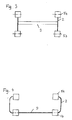
- a stiffening 9 designed as a bar that is resistant to bending and torsion, a possibility being shown in FIG. 4 of this bar that is resistant to bending and torsion and to execute the pendulum 2 as a component in such a way that the stiffening 9 designed as a bending and torsionally rigid rod connects the pendulum 2 at the level of the lower self-aligning bearing 5b.
- the upper self-aligning bearings 5 a on the bearing block 4 hold the upper ends of the side-by-side pendulums 2 at a distance A from one another, while the lower ends of the self-aligning 2 in the area of the lower self-aligning bearings 5 b have a distance A '.
- the distance A is greater than the distance A 'in such a ratio that, in the normal position of the car body 11, on the one hand, the pantograph 7 engages approximately centrally on the contact wire and, on the other hand, the imaginary extensions of the pendulum axles intersect in the center of rotation 10 of the car body 11.
- the frame 3, the pendulum 2 and / or the bearing blocks 4 can advantageously be made of electrically non-conductive material.
- pendulum 2 and the pedestals 4 are arranged one behind the other in an aerodynamically favorable manner and / or have an aerodynamically favorable outer contour which acts in both directions of travel. Between frame 3 and base frame 1, a drive can attack wherever there is a relative movement to the car body 11.
- the drive 8 a; 8 b is integrated as a rotary drive 8 b in a self-aligning bearing 5 a (optionally 5 b).
- the control of the position of the frame 3 and thus of the pantograph 7 relative to the contact wire takes place, as does the control of the drive for the synchronous movement of the car body tilting device via known systems, not shown and described here.
- the car body 11 is automatically pivoted into the normal position, and consequently the pantograph 7 also assumes its normal position.
- the vertical height deviation resulting from the tilting movement can be neglected, since there is sufficient scope for the pantograph 7 from the lower switch-off position to contacting the lowest contact wire height.
Landscapes
- Engineering & Computer Science (AREA)
- Power Engineering (AREA)
- Transportation (AREA)
- Mechanical Engineering (AREA)
- Current-Collector Devices For Electrically Propelled Vehicles (AREA)
Abstract
Description
Weiterhin bekannt (Railway Gazette International, Mai 1980 Blatt XI) ist eine Dachstromabnehmer-Einrichtung, die ebenfalls mit einem Gestänge vom Laufwerk zum Dachstromabnehmer ausgestattet ist, bei welchem ein Kipphebelsystem zur Anwendung kommt, das eine Gegensteuerung des Dachstromabnehmers zur Wagenkastenneigung bewirkt. Bei dieser Ausführungsform ist die Einengung des räumlichen Innenprofils und weiterhin der beschränkte Einsatz nur für Schienenfahrzeuge ohne Wagenübergangseinrichtungen als nachteilig anzusehen. Diese bekannten Ausführungsformen sind mittels Seilzüge oder Gestänge mit Winkelhebel variabel gestaltbar. Nach der DE 22 43 405 ist eine direkte Steuerung für den Dachstromabnehmer mittels doppelt wirkenden Hydraulikzylinder-Antrieben bekannt, die zu beiden Seiten des Wagenkastens angeordnet sind. Die Kammem der einander gegenüberliegenden Zylinder sind wechselseitig über Kreuz miteinander verbunden und die Verbindungsleitungen an die Zylinder der Stellvorrichtung angeschlossen. Ein Nachteil bei dieser Ausführung ist die Abhängigkeit vom System der Wagenkastenfederung.
In der DE 196 03 077 C2 wird eine Neigeeinrichtung für einen Dachstromabnehmer beschrieben, welche aus einem zweiteiligen Rahmen besteht, wobei diese Teile des Rahmens über trapezförmige Zwischenstücke miteinander verbunden sind. Während der obere Rahmenteil die Isolatoren nebst dem Dachstromabnehmer trägt, greifen die Pendel, an dem die Schwenkeinrichtung aufgehängt ist, an die Lager des unteren Rahmenteils an. Diese Bauform verlangt einen entsprechenden Bauraum, der gegebenenfalls anderweitig benötigt wird, im Dachbereich des Wagenkastens, welcher im wesentlichen von der Länge der Pendel bestimmt wird. Weiterhin bekannt ist eine Ausführungsform eines Pendelwagens (Broschüre "Neues aus Japan; herausgegeben von der Japan. Botschaft in der Bundesrepublik Deutschland, Nr. 156, März 1970), dessen flexibler Dachstromabnehmer aus einem Pendelsystem besteht, bei dem die Pendel stehend auf dem Fahrzeugdach angeordnet sind. Die in sich labile Ausführung würde sich bei Ausfall der Steuerung nicht von allein in die Normallage bewegen. Der Erfindung liegt das Problem zugrunde, einen Dachstromabnehmer für Schienenfahrzeuge mit Neigetechnik zu konzipieren, dessen Querneigesystem durch eine Pendelführung bewegt wird und dabei bei hoher Quer- und Längsstabilität keinen Bauraum im Dachbereich des Schienenfahrzeuges beansprucht. Das Problem wird bei einem gattungsgemäßen Dachstromabnehmer für Schienenfahrzeuge mit Neigetechnik nach dem Oberbegriff des Anspruchs 1 durch die im kennzeichnenden Teil des Anspruchs 1 genannten Merkmale gelöst. Eine zweckmäßige Ausgestaltung der Erfindung ist in den Unteransprüchen angegeben. Die mit der Erfindung erzielten Vorteile bestehen insbesondere darin, daß der vorgeschlagene Dachstromabnehmer in eine kompakte Leichtbaukonstruktion eingefügt ist, die besonders stabil in Fahrtrichtung und leicht pendelnd quer zur Fahrtrichtung ausgebildet ist, wobei der zu bewegende Teil der Leichtbaukonstruktion selbst, um ein Verdrehen um seine senkrecht stehende Achse (schlingern) weitgehend zu verhindern, mit einer hohen Querstabilität ausgestattet ist. Diese konstruktiv stabile Ausführung, die auch für den Einsatz auf Fahrzeugen mit hohen Geschwindigkeiten geeignet ist, weist unabhängig von der Wagenkastenfederung einen einfachen, unkomplizierten und fehlerfrei funktionierenden Aufbau auf, aus dessen geringe Massen sich geringe Trägheiten ergeben, wobei das Innenprofil des Schienenfahrzeuges, insbesondere im Dachbereich, nicht eingeengt wird.
- Fig. 1 -
- eine schematische Darstellung einer Frontansicht des neigbaren Dachstromabnehmers mit Linearantrieb,
- Fig. 2 -
- eine schematische Darstellung einer Frontansicht des neigbaren Dachstromabnehmers mit Drehantrieb,
- Fig. 3 -
- eine schematische Darstellung einer Seitenansicht der Stelleinrichtung für Dachstromabnehmer mit einem biege- und torsionssteifen Stab,
- Fig. 4 -
- eine schematische Darstellung einer Seitenansicht der Stelleinrichtung für Dachstromabnehmer, bei welchen zwei Pendel und der biege- und torsionssteife Stab aus einem Bauteil bestehen,
- Fig. 5 -
- eine schematische Darstellung eines Schienenfahrzeuges mit Dachstromabnehmer in Normallage,
- Fig. 6 -
- eine schematische Darstellung eines Schienenfahrzeuges mit Dachstromabnehmer in geneigter Kurvenlage.
Die oberen Pendellager 5 a am Lagerbock 4 halten die oberen Enden der nebeneinander angeordneten Pendel 2 in einem Abstand A zueinander, während die unteren Enden der Pendel 2 im Bereich der unteren Pendellager 5 b einen Abstand A' aufweisen. Der Abstand A ist dabei in solch einem Verhältnis größer als der Abstand A', daß in Normallage des Wagenkastens 11 zum einen der Dachstromabnehmer 7 annähernd mittig am Fahrdraht angreift und zum anderen sich die gedachten Verlängerungen der Pendelachsen im Drehpol 10 des Wagenkastens 11 schneiden. Vorteilhaft können der Rahmen 3, die Pendel 2 und/oder die Lagerböcke 4 aus elektrisch nichtleitendem Material ausgeführt sein.
Im Rahmen der aerodynamisch günstigen energiesparenden Gestaltung des gesamten Schienenfahrzeuges sind Pendel 2 und die Lagerböcke 4 aerodynamisch günstig hintereinander angeordnet und/oder verfügen über eine in beide Fahrtrichtungen wirkende aerodynamisch günstige Außenkontur.
Zwischen Rahmen 3 und Grundrahmen 1 kann ein Antrieb überall dort angreifen, wo es eine Relativbewegung zum Wagenkasten 11 gibt. Durch die Schwerkraft des Stromabnehmers 7 und des Rahmens 3, die in Richtung Gleisbogeninnenseite wirkt, muß der Antrieb 8 a; 8 b einen Gegendruck erzeugen. Bei zunehmender Geschwindigkeit hingegen zieht dieselbe Masse, nämlich die des Dachstromabnehmers 7 und des Rahmens 3, infolge der wirkenden Fliehkraft zur Gleisbogenaußenseite hin, und der Antrieb 8 a; 8 b muß dieser Fliehkraft entgegenwirken. In Fig. 1 ist dieser Antrieb 8 a; 8 b. der aus dieser Masse des pendelnd aufgehängten Rahmens 3 nebst Dachstromabnehmer 7 resultierenden Schwer- bzw. Fliehkraft entgegenwirkt als Linearantrieb 8 a ausgeführt, der zwischen Lagerbock 4 und einem Pendel 2 angeordnet an diese wirkend angreift, während in Fig. 2 der Antrieb 8 a; 8 b als Drehantrieb 8 b in einem Pendellager 5 a (gegebenenfalls 5 b) integriert ist. Die Steuerung der Stellung des Rahmens 3 und damit des Dachstromabnehmers 7 zum Fahrdraht erfolgt, wie auch die Steuerung des Antriebes zur Synchronbewegung der Wagenkastenneigeeinrichtung über bekannte, hier nicht dargestellte und beschriebene, Systeme.
Bei Störfällen wird der Wagenkasten 11 automatisch in die Normallage verschwenkt, und demzufolge nimmt auch der Dachstromabnehmer 7 seine Normallage ein. Die aus der Neigebewegung resultierende vertikale Höhenabweichung kann vernachlässigt werden, da für den Dachstromabnehmer 7 von der unteren Abschaltlage bis zum Anliegen bei niedrigster Fahrdrahthöhe genügend Spielraum vorhanden ist.
Claims (5)
- Dachstromabnehmer für Schienenfahrzeuge mit Neigetechnik, wobei der Dachstromabnehmer quer zur Längsachse des Fahrzeuges auf dessen Dach derart angeordnet ist, daß Pendel mittels Pendellager an Lagerboden eines in einem Dachgerippe integrierten Grundrahmen aufgehängt und über Pendellager mit einem Rahmen, der die Isolatoren mit dem Dachstromabnehmer aufnimmt, quer zur Fahrtrichtung gelenkig verbunden sind, und diese Pendel einen Abstand A zwischen ihren Pendellagern an den Lagerböcken und einen Abstand A' zwischen ihren Pendellagem am Rahmen in einem Verhältnis von A > A' aufweisen, dadurch gekennzeichnet, daß der Rahmen (3) oberhalb der Dachkontur angeordnet und in seiner Bauhöhe flach gehalten und eben ausgebildet ist, wobei sich die unteren Pendellager (5 b) mit den unteren Anschlußflächen der Isolatoren (6) höhenmäßig in nahezu einer Ebene befinden und die in Fahrtrichtung hintereinander liegenden Pendel (2) durch eine Versteifung (9) mindestens auf einer Seite momentensteif miteinander verbunden sind.
- Dachstromabnehmer nach Anspruch 1, dadurch gekennzeichnet, daß das Verhältnis A > A' der Abstände A und A' und damit die Schrägstellung der in Fahrtrichtung nebeneinander angeordneten Pendel (2) so ausgeführt ist, daß der gedachte Schnittpunkt der Längsachsen der Pendel (2) sich bei Normallage des Wagenkastens (11) in dessen Drehpol (10) befindet.
- Dachstromabnehmer nach einem der Ansprüche 1 oder 2, dadurch gekennzeichnet, daß die gegenläufige Neigung des Dachstromabnehmers (7) relativ zum Wagenkasten (1) über einen Antrieb (8a oder 8 b) erfolgt, welcher einerseits bei einer Ausführung als Linearantrieb (8 a) zwischen Rahmen (3) und Grundrahmen (1) angreift und andererseits bei einer Ausführung als Drehantrieb (8 b) in einem Pendellager (5 a oder 5 b) integriert ist.
Dachstromabnehmer nach einem der Ansprüche 1 bis 3, dadurch gekennzeichnet, daß Rahmen (3), Pendel (2) und/oder Lagerböcke (4) aus elektrisch nichtleitendem Material ausgeführt sind. - Dachstromabnehmer nach einem der Ansprüche 1 bis 4, dadurch gekennzeichnet, daß die Pendel (2) und Lagerböcke (4) aerodynamisch günstig hintereinander angeordnet sind und/oder über eine aerodynamsich günstige Außenkontur verfügen.
- Dachstromabnehmer nach einem der Ansprüche 1 bis 5, dadurch gekennzeichnet, daß die Versteifung (9) der in Fahrtrichtung hintereinander liegenden Pendel (2) als biege- und torsionsfesten Stab ausgeführt ist und gegebenenfalls gemeinsam mit den Pendeln (2) aus einem Bauteil bestehen.
Applications Claiming Priority (2)
| Application Number | Priority Date | Filing Date | Title |
|---|---|---|---|
| DE19805950A DE19805950C2 (de) | 1998-02-13 | 1998-02-13 | Dachstromabnehmer für Schienenfahrzeuge mit Neigetechnik |
| DE19805950 | 1998-02-13 |
Publications (2)
| Publication Number | Publication Date |
|---|---|
| EP0936100A1 true EP0936100A1 (de) | 1999-08-18 |
| EP0936100B1 EP0936100B1 (de) | 2010-12-15 |
Family
ID=7857641
Family Applications (1)
| Application Number | Title | Priority Date | Filing Date |
|---|---|---|---|
| EP99103267A Expired - Lifetime EP0936100B1 (de) | 1998-02-13 | 1999-02-05 | Dachstromabnehmer für Schienenfahrzeuge mit Neigetechnik |
Country Status (4)
| Country | Link |
|---|---|
| EP (1) | EP0936100B1 (de) |
| AT (1) | ATE491593T1 (de) |
| CZ (1) | CZ293081B6 (de) |
| DE (2) | DE19805950C2 (de) |
Cited By (1)
| Publication number | Priority date | Publication date | Assignee | Title |
|---|---|---|---|---|
| FR2800680A1 (fr) * | 1999-11-10 | 2001-05-11 | Alstom | Ensemble de captage de courant et vehicule ferroviaire correspondant |
Citations (2)
| Publication number | Priority date | Publication date | Assignee | Title |
|---|---|---|---|---|
| DE29613541U1 (de) * | 1996-08-05 | 1997-06-05 | Siemens AG, 80333 München | Schienenfahrzeug |
| DE19614554A1 (de) * | 1996-04-12 | 1997-10-16 | Siemens Ag | Schienenfahrzeug |
Family Cites Families (3)
| Publication number | Priority date | Publication date | Assignee | Title |
|---|---|---|---|---|
| AT327289B (de) * | 1971-09-08 | 1976-01-26 | Siemens Ag Oesterreich | Schienenfahrzeug mit einem scherenstromabnehmer |
| SE8105354L (sv) * | 1981-09-09 | 1983-03-10 | Asea Ab | Anordning av stromavtagare pa ett sparbundet fordon |
| DE19603077C2 (de) * | 1996-01-19 | 1997-11-20 | Inst Schienenfahrzeuge | Stromabnehmer für Schienenfahrzeuge mit Neigetechnik |
-
1998
- 1998-02-13 DE DE19805950A patent/DE19805950C2/de not_active Expired - Fee Related
-
1999
- 1999-02-05 DE DE59915226T patent/DE59915226D1/de not_active Expired - Lifetime
- 1999-02-05 EP EP99103267A patent/EP0936100B1/de not_active Expired - Lifetime
- 1999-02-05 AT AT99103267T patent/ATE491593T1/de active
- 1999-02-10 CZ CZ1999444A patent/CZ293081B6/cs not_active IP Right Cessation
Patent Citations (2)
| Publication number | Priority date | Publication date | Assignee | Title |
|---|---|---|---|---|
| DE19614554A1 (de) * | 1996-04-12 | 1997-10-16 | Siemens Ag | Schienenfahrzeug |
| DE29613541U1 (de) * | 1996-08-05 | 1997-06-05 | Siemens AG, 80333 München | Schienenfahrzeug |
Cited By (3)
| Publication number | Priority date | Publication date | Assignee | Title |
|---|---|---|---|---|
| FR2800680A1 (fr) * | 1999-11-10 | 2001-05-11 | Alstom | Ensemble de captage de courant et vehicule ferroviaire correspondant |
| EP1099590A1 (de) * | 1999-11-10 | 2001-05-16 | Alstom | Stromabnehmervorrichtung und entsprechendes Schienenfahrzeug |
| US6363862B1 (en) | 1999-11-10 | 2002-04-02 | Alstom | Power pick-up assembly and corresponding railway vehicle |
Also Published As
| Publication number | Publication date |
|---|---|
| CZ293081B6 (cs) | 2004-02-18 |
| DE19805950A1 (de) | 1999-08-26 |
| EP0936100B1 (de) | 2010-12-15 |
| ATE491593T1 (de) | 2011-01-15 |
| DE19805950C2 (de) | 2000-05-11 |
| CZ44499A3 (cs) | 1999-09-15 |
| DE59915226D1 (de) | 2011-01-27 |
Similar Documents
| Publication | Publication Date | Title |
|---|---|---|
| DE2660079C3 (de) | Verstelleinrichtung für einen Schienenfahrzeug-Radsatz in einem zwei- oder mehrachsigen Drehgestell | |
| EP0783415B1 (de) | Achsaufhängung für starrachsen in fahrzeugen | |
| DE69404031T2 (de) | Aus mehreren modulen zusammengestelltes und durch eine zusammengesetzte verbindung gekoppeltes fahrzeug | |
| DE2839904C2 (de) | Wankstützvorrichtung für ein Schienenfahrzeug mit Drehgestellen | |
| DE3826930C2 (de) | Radaufhängungssystem | |
| DE10133424A1 (de) | Hinterachse eines Personenkraftwagens mit fünf einzelnen Lenkern | |
| DE3740395A1 (de) | Rueckwaertiges aufhaengungssystem fuer kraftfahrzeuge | |
| DE2945802A1 (de) | Vorderradaufhaengung fuer kraftfahrzeuge | |
| DE102014205632A1 (de) | Einzelradaufhängung sowie Hinterachse mit Einzelradaufhängungen für ein Fahrzeug und entsprechend ausgestattetes Fahrzeug | |
| WO2011113456A1 (de) | Kraftwagen | |
| DE102014205635A1 (de) | Einzelradaufhängung sowie Hinterachse mit Einzelradaufhängungen für ein Fahrzeug und entsprechend ausgestattetes Fahrzeug | |
| EP0848676B1 (de) | Drehgestell für schienenfahrzeuge | |
| DE60017067T2 (de) | Triebdrehgestell für ein Schienenfahrzeug und Schienenfahrzeug mit solch einem Drehgestell | |
| DE202014101432U1 (de) | Einzelradaufhängung sowie Hinterachse mit Einzelradaufhängungen für ein Fahrzeug und entsprechend ausgestattetes Fahrzeug | |
| EP0699149B1 (de) | Wankstütze für schienenfahrzeuge mit einer querneigeeinrichtung | |
| DE19603077C2 (de) | Stromabnehmer für Schienenfahrzeuge mit Neigetechnik | |
| DE1904615A1 (de) | Achsaufhaengung fuer Leitschienenbahnfahrzeuge | |
| DE2801261C2 (de) | Selbsttragende Fahrerkabine für Nutzfahrzeuge | |
| EP0975504B1 (de) | Fahrzeug | |
| DE3221755A1 (de) | Drehgestell fuer ein schienenfahrzeug | |
| EP0936100B1 (de) | Dachstromabnehmer für Schienenfahrzeuge mit Neigetechnik | |
| EP0485732A2 (de) | Baufahrzeug, vorzugsweise Radlader mit Knickrahmenlenkung | |
| DE60011014T2 (de) | Vorrichtung mit einem ersten Rahmen und einem zweiten Rahmen, das lateral zum ersten Rahmen pendelt, und ein entsprechendes Schienenfahrzeug | |
| WO1999042975A1 (de) | Bewegungssystem | |
| DE3039051A1 (de) | Starrachse, insbesondere angetriebene hinterachse fuer fahrzeuge |
Legal Events
| Date | Code | Title | Description |
|---|---|---|---|
| PUAI | Public reference made under article 153(3) epc to a published international application that has entered the european phase |
Free format text: ORIGINAL CODE: 0009012 |
|
| AK | Designated contracting states |
Kind code of ref document: A1 Designated state(s): AT CH DE ES FI FR GB IT LI PT SE |
|
| AX | Request for extension of the european patent |
Free format text: AL;LT;LV;MK;RO;SI |
|
| 17P | Request for examination filed |
Effective date: 20000201 |
|
| AKX | Designation fees paid |
Free format text: AT CH DE ES FI FR GB IT LI PT SE |
|
| RAP1 | Party data changed (applicant data changed or rights of an application transferred) |
Owner name: BOMBARDIER TRANSPORTATION (BAHNTECHNOLOGIE) HOLDIN |
|
| 17Q | First examination report despatched |
Effective date: 20071128 |
|
| GRAP | Despatch of communication of intention to grant a patent |
Free format text: ORIGINAL CODE: EPIDOSNIGR1 |
|
| GRAC | Information related to communication of intention to grant a patent modified |
Free format text: ORIGINAL CODE: EPIDOSCIGR1 |
|
| GRAS | Grant fee paid |
Free format text: ORIGINAL CODE: EPIDOSNIGR3 |
|
| GRAA | (expected) grant |
Free format text: ORIGINAL CODE: 0009210 |
|
| RAP1 | Party data changed (applicant data changed or rights of an application transferred) |
Owner name: BOMBARDIER TRANSPORTATION (BAHNTECHNOLOGIE) HOLDIN |
|
| AK | Designated contracting states |
Kind code of ref document: B1 Designated state(s): AT CH DE ES FI FR GB IT LI PT SE |
|
| REG | Reference to a national code |
Ref country code: GB Ref legal event code: FG4D Free format text: NOT ENGLISH Ref country code: CH Ref legal event code: EP |
|
| REF | Corresponds to: |
Ref document number: 59915226 Country of ref document: DE Date of ref document: 20110127 Kind code of ref document: P |
|
| REG | Reference to a national code |
Ref country code: CH Ref legal event code: NV Representative=s name: ABREMA AGENCE BREVET ET MARQUES, GANGUILLET |
|
| REG | Reference to a national code |
Ref country code: SE Ref legal event code: TRGR |
|
| PG25 | Lapsed in a contracting state [announced via postgrant information from national office to epo] |
Ref country code: FI Free format text: LAPSE BECAUSE OF FAILURE TO SUBMIT A TRANSLATION OF THE DESCRIPTION OR TO PAY THE FEE WITHIN THE PRESCRIBED TIME-LIMIT Effective date: 20101215 |
|
| PG25 | Lapsed in a contracting state [announced via postgrant information from national office to epo] |
Ref country code: ES Free format text: LAPSE BECAUSE OF FAILURE TO SUBMIT A TRANSLATION OF THE DESCRIPTION OR TO PAY THE FEE WITHIN THE PRESCRIBED TIME-LIMIT Effective date: 20110326 Ref country code: PT Free format text: LAPSE BECAUSE OF FAILURE TO SUBMIT A TRANSLATION OF THE DESCRIPTION OR TO PAY THE FEE WITHIN THE PRESCRIBED TIME-LIMIT Effective date: 20110415 |
|
| PLBE | No opposition filed within time limit |
Free format text: ORIGINAL CODE: 0009261 |
|
| STAA | Information on the status of an ep patent application or granted ep patent |
Free format text: STATUS: NO OPPOSITION FILED WITHIN TIME LIMIT |
|
| 26N | No opposition filed |
Effective date: 20110916 |
|
| GBPC | Gb: european patent ceased through non-payment of renewal fee |
Effective date: 20110315 |
|
| REG | Reference to a national code |
Ref country code: DE Ref legal event code: R097 Ref document number: 59915226 Country of ref document: DE Effective date: 20110916 |
|
| PG25 | Lapsed in a contracting state [announced via postgrant information from national office to epo] |
Ref country code: GB Free format text: LAPSE BECAUSE OF NON-PAYMENT OF DUE FEES Effective date: 20110315 |
|
| PGFP | Annual fee paid to national office [announced via postgrant information from national office to epo] |
Ref country code: CH Payment date: 20120221 Year of fee payment: 14 Ref country code: FR Payment date: 20120227 Year of fee payment: 14 |
|
| PGFP | Annual fee paid to national office [announced via postgrant information from national office to epo] |
Ref country code: DE Payment date: 20120221 Year of fee payment: 14 |
|
| PGFP | Annual fee paid to national office [announced via postgrant information from national office to epo] |
Ref country code: SE Payment date: 20120217 Year of fee payment: 14 Ref country code: IT Payment date: 20120224 Year of fee payment: 14 |
|
| PGFP | Annual fee paid to national office [announced via postgrant information from national office to epo] |
Ref country code: AT Payment date: 20120213 Year of fee payment: 14 |
|
| REG | Reference to a national code |
Ref country code: CH Ref legal event code: PL |
|
| REG | Reference to a national code |
Ref country code: SE Ref legal event code: EUG |
|
| REG | Reference to a national code |
Ref country code: AT Ref legal event code: MM01 Ref document number: 491593 Country of ref document: AT Kind code of ref document: T Effective date: 20130228 |
|
| PG25 | Lapsed in a contracting state [announced via postgrant information from national office to epo] |
Ref country code: CH Free format text: LAPSE BECAUSE OF NON-PAYMENT OF DUE FEES Effective date: 20130228 Ref country code: AT Free format text: LAPSE BECAUSE OF NON-PAYMENT OF DUE FEES Effective date: 20130228 Ref country code: SE Free format text: LAPSE BECAUSE OF NON-PAYMENT OF DUE FEES Effective date: 20130206 Ref country code: LI Free format text: LAPSE BECAUSE OF NON-PAYMENT OF DUE FEES Effective date: 20130228 |
|
| REG | Reference to a national code |
Ref country code: FR Ref legal event code: ST Effective date: 20131031 |
|
| REG | Reference to a national code |
Ref country code: DE Ref legal event code: R119 Ref document number: 59915226 Country of ref document: DE Effective date: 20130903 |
|
| PG25 | Lapsed in a contracting state [announced via postgrant information from national office to epo] |
Ref country code: IT Free format text: LAPSE BECAUSE OF NON-PAYMENT OF DUE FEES Effective date: 20130205 |
|
| PG25 | Lapsed in a contracting state [announced via postgrant information from national office to epo] |
Ref country code: FR Free format text: LAPSE BECAUSE OF NON-PAYMENT OF DUE FEES Effective date: 20130228 Ref country code: DE Free format text: LAPSE BECAUSE OF NON-PAYMENT OF DUE FEES Effective date: 20130903 |