EP0936158A1 - Müllbehälter mit einer Vorrichtung zur automatischen Abgabe von Beuteln - Google Patents
Müllbehälter mit einer Vorrichtung zur automatischen Abgabe von Beuteln Download PDFInfo
- Publication number
- EP0936158A1 EP0936158A1 EP98400360A EP98400360A EP0936158A1 EP 0936158 A1 EP0936158 A1 EP 0936158A1 EP 98400360 A EP98400360 A EP 98400360A EP 98400360 A EP98400360 A EP 98400360A EP 0936158 A1 EP0936158 A1 EP 0936158A1
- Authority
- EP
- European Patent Office
- Prior art keywords
- container
- bag
- base unit
- bags
- aperture
- Prior art date
- Legal status (The legal status is an assumption and is not a legal conclusion. Google has not performed a legal analysis and makes no representation as to the accuracy of the status listed.)
- Withdrawn
Links
- 239000002699 waste material Substances 0.000 title claims abstract description 51
- 229920003023 plastic Polymers 0.000 claims abstract description 16
- 239000004033 plastic Substances 0.000 claims abstract description 16
- 238000000034 method Methods 0.000 claims description 12
- 238000006073 displacement reaction Methods 0.000 claims description 3
- 238000007789 sealing Methods 0.000 claims description 2
- 238000009877 rendering Methods 0.000 description 4
- 238000004140 cleaning Methods 0.000 description 3
- 238000001125 extrusion Methods 0.000 description 3
- 229920001684 low density polyethylene Polymers 0.000 description 3
- 239000004702 low-density polyethylene Substances 0.000 description 3
- 239000000463 material Substances 0.000 description 2
- 239000002184 metal Substances 0.000 description 2
- -1 polyethylene Polymers 0.000 description 2
- 238000003825 pressing Methods 0.000 description 2
- 238000000926 separation method Methods 0.000 description 2
- 239000002689 soil Substances 0.000 description 2
- 241001272567 Hominoidea Species 0.000 description 1
- 239000004698 Polyethylene Substances 0.000 description 1
- 239000004743 Polypropylene Substances 0.000 description 1
- 230000015556 catabolic process Effects 0.000 description 1
- 238000010276 construction Methods 0.000 description 1
- 230000002950 deficient Effects 0.000 description 1
- 238000006731 degradation reaction Methods 0.000 description 1
- 230000035622 drinking Effects 0.000 description 1
- 230000007937 eating Effects 0.000 description 1
- 230000000694 effects Effects 0.000 description 1
- 239000012530 fluid Substances 0.000 description 1
- 231100001261 hazardous Toxicity 0.000 description 1
- 229920000092 linear low density polyethylene Polymers 0.000 description 1
- 239000004707 linear low-density polyethylene Substances 0.000 description 1
- 230000014759 maintenance of location Effects 0.000 description 1
- 239000002984 plastic foam Substances 0.000 description 1
- 229920000573 polyethylene Polymers 0.000 description 1
- 229920001155 polypropylene Polymers 0.000 description 1
- 239000012858 resilient material Substances 0.000 description 1
- 230000000284 resting effect Effects 0.000 description 1
- 229910052710 silicon Inorganic materials 0.000 description 1
- 239000010703 silicon Substances 0.000 description 1
- 230000000391 smoking effect Effects 0.000 description 1
- 239000007787 solid Substances 0.000 description 1
- 239000000725 suspension Substances 0.000 description 1
- 230000029305 taxis Effects 0.000 description 1
- 239000000326 ultraviolet stabilizing agent Substances 0.000 description 1
Images




Classifications
-
- B—PERFORMING OPERATIONS; TRANSPORTING
- B65—CONVEYING; PACKING; STORING; HANDLING THIN OR FILAMENTARY MATERIAL
- B65F—GATHERING OR REMOVAL OF DOMESTIC OR LIKE REFUSE
- B65F1/00—Refuse receptacles; Accessories therefor
- B65F1/04—Refuse receptacles; Accessories therefor with removable inserts
- B65F1/06—Refuse receptacles; Accessories therefor with removable inserts with flexible inserts, e.g. bags or sacks
- B65F1/062—Refuse receptacles; Accessories therefor with removable inserts with flexible inserts, e.g. bags or sacks having means for storing or dispensing spare bags
Definitions
- the present invention relates to a waste receptacle. More particularly, the invention is concerned with providing a waste receptacle wherein a fresh plastic garbage bag appears therein automatically upon the removal for disposal of a full bag.
- Waste receptacles are therefore manufactured and distributed to suit all conceivable needs, ranging in size from about one liter - for use in cars and taxis, up to the 56-gallon (215 liter) size found in factories and large public kitchens.
- waste receptacle The need for a waste receptacle is particularly felt where the waste generated is of a moist nature, such as in kitchens, or when the waste is contaminating or hazardous, such as waste from hospitals. It is, therefore, a common practice to line the inner faces of a waste bin with a plastic bag.
- Such bags are often made of low-density polyethylene or linear low-density polyethylene, and are manufactured and sold in packages of individually-cut bags, or in the form of rolls.
- a convenient way to store such a role of bags would be in a roll of bags which is formed by a long, cylindrical, usually folded, flexible extrusion or sheet of bags.
- the length of the extrusion or sheet of bags is preferably partially subdivided by a pair of adjacent transverse lines every 50 to 100 centimeters, a first solid line serving to seal the base of one bag and a second, adjacent perforated line providing a convenient tear line for separating and opening the next bag.
- Dispensers for the rolls of plastic bags are known, but the dispensers do little to alleviate the task of changing a full bag of waste, placing the new bag in the waste bin and the like, as described hereinabove.
- the present invention is a waste receptacle for collecting waste, wherein a fresh plastic garbage bag appears therein automatically upon the removal for disposal of a full bag.
- a waste receptacle including: (a) a hollow container having a interior space, said interior space having an entry facing vertically; (b) a substantially elongated aperture, having an outer edge, formed in a lower surface of said container and said aperture communicating with said interior space in said hollow container; and (c) a base situated beneath said container and having a recess formed in said base for situating a plurality of interconnected bags such that a bag is insertable into said aperture.
- the base features a gripping surface for gripping said bags.
- the gripping surface features includes transverse resilient bands for securing said container and for preventing the inadvertent displacement of said bags.
- the container includes a pedal.
- the includes is hingedly attached to said container.
- the device further includes a bag locking mechanism.
- the apparatus further includes a lid.
- the device is wall mountable.
- the outer edge includes at least one resilient gripper for gripping said gripping surface and sealing said aperture.
- the container is dimensioned enabling nesting of a plurality of said containers.
- the container includes a nesting ridge for situating said base.
- the bags are arranged in the shape of a roll.
- a method for using a waste receptacle wherein a fresh plastic garbage bag appears therein automatically upon the removal for disposal of a full bag including the steps of: (a) providing a waste receptacle including: (i) a hollow container having an interior space, said interior space having an entry facing vertically; (ii) a substantially elongated aperture, having an outer edge, formed in a lower surface of said container and said aperture communicating with said interior space in said hollow container; and (iii) a base situated beneath said container and having a recess formed in said base for situating a plurality of interconnected bags such that a bag is insertable into said aperture; (b) passing a bag through said aperture; (c) pulling said bag substantially towards said opening and over said rim; and (d) displacing said container towards said base.
- the method furthr includes the steps of: (a) displacing said container substantially away from said base; and (b) inserting said bags into said recess.
- the method furthr includes the steps of: (a) verifying said bag needs replacing; (b) displacing said bag substantially towards said opening; (c) disconnecting said bag from adjacent bag; (d) disposing said bag; and (e) repeating steps (e) and (f) in claim 13.
- the method furthr includes the steps of: (a) verifying said plurality of bags have been depleted; and (b) repeating steps (a) - (f) in claim 13.
- the objective of providing a waste receptacle wherein a fresh plastic garbage bag appears therein automatically upon the removal for disposal of a full bag is achieved by providing a receptacle for the collection of refuse, which has an attached holder for the revolvable retention of a roll of connected plastic garbage disposal bags, and an aperture formed therein passable therethrough for dispensation of a line of connected bags from the roll positioned in the holder to the inner volume of the receptacle, in a manner allowing the user to cover the inner face of the receptacle with the leading bag in the line.
- the present invention is of a waste receptacle for the disposal of waste by prodding a waste receptacle wherein a fresh plastic garbage bag appears therein automatically upon the removal for disposal of a bag which has become heavy or has a significant quantity of refuse therein or any other reason deemed sufficient by the user.
- Waste receptacle 27 for collecting a quitity of waste material 41 .
- Waste receptacle 27 includes a hollow container 42 having a length and a width featuring a substantially elongated aperture 50 , having a outer edge 137 , formed in a lower surface 74 of container 42 and aperture 50 communicating with a cavity 138 in hollow container 42 , container 42 having a entry facing vertically.
- Waste receptacle 27 also includes a base unit 31 situated beneath container 42 and having a recess 28 formed in base unit 31 for situating a plurality of interconnected bags 46 .
- a convenient form of dispensing and storing bags 46 is by placing bags 46 in recess 28 is when bags 46 are arranged in the shape of a roll 45 .
- recess 28 revolvably retains roll 45 of connected plastic garbage disposal bags 46 with ease.
- recess 28 is arranged to accommodate a number of rolls 45 in addition to roll 45 in use.
- Bags 46 are typically made of low density polyethylene or linear, low-density polyethylene.
- Roll 45 includes a long, cylindrical, folded, flexible extrusion, its length partially subdivided by a pair of adjacent transverse lines 48 every 50 to 100 centimeters.
- the first line (not shown) is a solid, heat-sealed seam serving to seal the base of each bag.
- the second line (not shown) is a perforated line adjacent to the first line and provides a convenient tear line for separating and opening the next bag thereafter.
- Aperture 50 formed in container 42 allows passage of a line of connected bags 46 from roll 45 to the inner volume of container 42 . After withdrawing and then separating a full bag 46f from a adjacent bag 46a , the user need only fold a open edge 52 of bag 46a over a rim 29 of container 42 , thereby rendering new bag 46a ready for use.
- Base unit 31 preferably includes a gripping surface 71 attached thereto, or integrally formed therewith. Gripping surface 71 is accommodated by apes 50 formed in holder 28 and grips sheet of bags 46 when the user displaces container 42 by applying pressure, preferably with his foot, on a pedal 73 . Container 42 is properly aligned in relation to base unit 31 using a guide 75 .
- Receptacle 27 may be molded of polyethylene, polypropylene, or a similar material. For larger sizes, a structural plastic foam is preferable.
- those receptacles 27 used outdoors, are substantially made of metal, or plastic containing an ultraviolet stabilizer thereby protecting the plastic against sunlight degradation, wherein the word substantially, in this context, implies most elements of the receptacle 27 are made of metal or the aforementioned plastic variants.
- FIG. 2 A second embodiment of the invention is shown in Figure 2, wherein a second receptacle 30 is provided with a bag locking mechanism 32 .
- Bag locking mechanism 32 is operated by the user in order to grip bag 46 adjacent to bag 46u in use.
- Bag locking mechanism 32 shown in Figure 2 is designed to be operated by the user's foot, thereby leaving his hands free to grip, tension and separate bag 46u , from roll 45 once bag 46u is replete with refuse.
- bag locking mechanism 32 includes a foot-operable lever 34 , pivotally attached to receptacle 30 at 47 and including a gripping element 36 . Foot pressure on lever 34 results in element 36 pressing bag 46 against a securing surface 38 of receptacle 30 , thereby enabling the easy separation of bag 46 from adjacent bag 46u .
- Roll 45 is situated in a roll holder 40 which holder 40 is provided with a upper opening 53 , for the convenient replacement of a new roll 45 (not shown) once the user wishes to replace roll 45 which may occur upon the partial and/or total depletion of roll 45 being used.
- Waste receptacle 44 is shown with a user-operable securing mechanism 49 , for temporarily preventing roll 45 revolving.
- the securing of roll 45 facilitates handling a full garbage bag 46 which then may be conveniently gripped, tensioned and separated from adjacent bag 46u .
- Waste receptacle 44 further includes a gripping element 130 attached to, or integrally formed with a foot pedal 51 .
- Pedal 51 is also attached to, or integrally formed with, a lever 55 , pivoted at 59 . Applying an appropriate degree of pressure on peda l 51 renders roll 45 momentarily unrevolvable for as long as the pressure on roll 45 persists.
- Suspending receptacle 44 is best achieved, according to this embodiment, by using a bracket 132 placed in a vertical surface such as a wall 54 and designed to accept a catch 134 attached to, or integrally formed with receptacle 44 .
- Receptacle 44 as shown in Figure 3, is adapted enabling suspension of receptacle 44 from vertical surface 54 .
- FIG. 4 shows a fourth embodiment of a waste receptacle 56 .
- a roll holder 58 retaining roll 45 is positioned within a waste-receiving container 60 .
- Loading of a new roll 45 is achieved by placing roll 45 axially through a aperture 62 formed in container 60 .
- This construction is less likely to attract thieves, tamperers or vandals, and thus is well-suited to use in public areas.
- FIG. 5 depicts a fifth, especially preferred, embodiment of the present invention.
- a receptacle 64 similar to receptacle 27 as described hereinabove, is provided with a base unit 66 , which supports a waste container 68 which container 68 is similar to container 42 described hereinabove and shown in Figure 1.
- Base unit 66 is equipped with a bag holder 69 for holding roll 45 in place.
- Base unit 66 includes a projection 71 , which projection 71 is designed to be accommodated by aperture 72 formed in bottom surface 74 . When projection 71 is accepted by aperture 72 , projection 71 then engages bottom surface 74 allowing ready detachment of bag 46a from bag 46u .
- Projection 71 is designed to create a sufficient margin between itself and aperture 72 formed in bottom surface 74 to allow passage of bag 46a pursuant to the user pulling bag 46u , thereby allowing bag 46a to enter container 68 .
- Aperture 72 formed in bottom surface 74 is further preferably formed with at least one, and preferably two as shown, upraised lip 67 , such that any leakage from refuse in bag 46u is contained in container 68 and does not soil base unit 66 and/or recession 69 .
- Container 68 is guided at a guide 75 to rest on top of base unit 66 , and may be readily displaced for the purposes of cleaning and/or loading of a new roll 45 .
- FIG. 6 A sixth embodiment is shown in Figure 6, wherein a waste container 80 is provided with a hinge 82 proximal to a base unit 78 situated beneath container 80 .
- Container 80 further includes a receptacle 76 similar to receptacle 64 shown in Figure 5 and described hereinabove as well as a recession 88 situated between bottom surface 74 of container 68 and a lower surface 70 of base unit 78 . Due to the partial acceptance of roll 45 in recession 88 and the lower half of roll 45 resting in base unit 78 , base unit 78 may be rendered lower than base unit 66 in Figure 5, thus economizing on the overall size and space used for container 80 .
- container 80 In order to successfully reload bag holder 88 with a new roll 45 , container 80 is displaced sufficiently, by pivoting container 80 about hinge 82 until roll 45 may be readily accepted in holder 88 .
- an urging mechanism or bias (not shown) can be provided for displacing container 80 back towards base unit 86 about hinge 82 , and even to provide the force needed for gripping the sheet of bags 46 and enabling easy detachment of bag 46a from bag 46u , eliminating the need for foot pedal 73 shown in Figure 1.
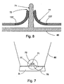
- Figures 7 and 8 show a seventh preferred embodiment including a container 80 .
- container 80 rests on base unit 31 , which base unit 31 includes a holder 28 similar to holder 28 in Figure 1.
- container 80 may be displaced from base unit 31 for the purpose of loading and/or replacing roll 45 (not shown).
- container 80 includes aperture 72 formed therein as well as gripping surface 71 .
- Container 80 further includes at least one, and preferably two as shown, resilient grippers 77 attached to, or integrally formed with, outer edge 137 of aperture 72 formed in container 80 .
- Grippers 77 act to seal aperture 72 preventing ay refuse or fluids from seeping and/or entering into base unit 31 or holder 28 .
- grippers 77 are made of rubber, silicon or a different material having the same properties.
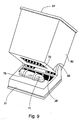
- FIG. 9 Yet another configuration is shown in Figure 9, wherein a similar container 80 including gripping surface 71 attached to base unit 31 , which base unit 31 further includes at least one, two are shown, transverse bads 79 such that when container 80 is pivoted about hinge 82 thereby making aperture 72 accept surface 71 with bands 79 resulting in the application of a degree of pressure between bands 79 and aperture 72 sufficient to secure container 80 to base unit 31 .
- Bands 79 are used for preventing the inadvertent displacement of bags 46 as well as bands 79 potentially also serving to provide the force needed for gripping the sheet of bags 46 (not shown) to allow the ready detachment of bag 46a (not shown) from bag 46u (not shown), thereby eliminating the need for foot pedal 73 (not shown).
- bands 79 are made of a resilient material such as rubber.
- container 80 further includes a rim 94 for easier securing of bag 46a (not shown) being used.
- Figure 10 depicts a especially preferred embodiment of the present invention wherein receptacle 64 , similar to receptacle 64 in Figure 5, is provided with a base unit 31 , which base unit 31 supports a waste container 68a which container 68a is similar to another container 68b .
- Base unit 31 is similarly equipped with a bag holder 69 for holding roll 45 in place.
- Base unit 31 includes projection 71 designed to be accommodated by aperture 72 formed in bottom surface 74 of container 68a .
- projection 71 When projection 71 is accepted by aperture 72 , projection 71 engages bottom surface 74 allowing the similar ready detachment of bag 46a (not shown) from bag 46u (not shown). Projection 71 is in a similar fashion designed to create a sufficient margin between itself and aperture 72 formed in bottom surface 74 to allow passage of bag 46a (not shown) pursuant to the user pulling bag 46 (not shown) in a similar manner, thereby allowing bag 46a (not shown) to enter container 68 . Aperture 72 formed in bottom surface 74 is similarly formed with two upraised lips 67 , such that any leakage is contained in container 68 and does not soil base unit 31 and/or recession 69 . Container 68a is displaceable about a hinge 83 to rest on top of base unit 31 , container 68a may also be readily displaced the purposes of cleaning and/or loading of a new roll 45 .
- Base unit 31 is dimensioned to enable nesting of a plurality of containers 68 . Specifically, base unit 31 is dimensioned to be accommodated by container 68 thereby rendering brie unit 31 nestable in container 68 for easier storage ad transportation.
- One of the advantages of containers 68 having a nesting capability is the ability of convenient storage in warehouses while economizing in space until containers 68 are used and/or sold.
- the nesting is achieved by raising container 68a above similar container 68b and then accommodating container 68a in container 68b as shown by the arrow designated "t" thus economizing the space taken up by containers 68a and 68b .
- the procedure described hereinabove is repeated as necessary according to the number of containers 68a and 68b to be nested.
- FIG. 11 and 12 Another nestable configuration is shown in Figures 11 and 12, wherein a container 90 includes a rim 94 similar to rim 29 shown in Figure 1, and described hereinabove in relation to the first embodiment.
- Container 90 also includes a bottom surface 96 having a nesting ridge 92 .
- a base 100 ( Figures 13 and 14) is detached and stored separately thereby enabling storage of spare parts without having recourse to storing containers 90 and bases 100 attached one to each other.
- Base 100 includes a hollow cavity 102 formed therein as well as a roll holder 106 protruding into cavity 102 .
- Base 100 further includes a gripping surface 108 including a cavity 109 formed therein.
- Cavity 109 is sized to accept the upper end of gripping surface 108 when another base 108 is placed therebeneath. Due to base 100 having cavity 102 formed therein ad holder 106 protruding into cavity 102 as well as gripping surface 108 having cavity 109 , bases 100 are nestable in the manner shown in Figure 13.
- FIG. 15 A further nestable configuration is shown in Figures 15 and 16, wherein a container 110 includes a nesting ridge 112 and a rim 114 . Furthermore, a base 117 similar to base 100 ( Figures 13 and 14) is attached to, or integrally formed with, container 110 . Base 117 is also dimensioned to have a smaller size than container 110 thereby rendering base 117 nestable in container 110 for easier storage and transportation. Typically, when containers 110 are nested, base 117 will rest on ridge 112 .
- Figures 17 and 18 depict yet a further configuration which is identical in all aspects to the configuration of Figures 15 and 16 but for the absence of nesting ridge 112 shown in Figures 15 and 16.
- Container 110 similarly includes rim 114 and base 117 is likewise attached to, or integrally formed with, container 110 .
- Base 117 is also dimensioned to have a smaller size than container 110 thereby rendering base 117 nestable in container 110 for easier storage and transportation.
- base 117 will rest on base 117 of container 110 immediately therebeneath. Owing to the absence of any ridges, the present configuration offers an alternative and more compact nesting configuration than the configuration shown in Figures 15 and 16 and described hereinabove for the convenience of the user and/or retailer.
- Figures 19-25 show the steps of using a waste container 120 , as well as loading and replacing a bag 46u according to the present invention.
- container 120 with a lid 57 and base 78 is shown prior to being loaded. The process is achieved by performing the following steps: first, displacing container 120 substantially away from base 78 . Second, inserting bags 46 into recess 28 . Third, passing bag 46 through aperture 72 . Fourth, displacing container 120 towards base 78 and then pulling bag 46 substantially towards opening 138 and over rim 94 . Alternatively and preferably it would also be possible to pull bag 46 substantially towards opening 138 and over rim 94 and then to displace container 120 towards base 78 .
- container 120 Once container 120 has been used as described hereinabove, the user will verify bag 46 should be replaced and soon thereafter will displace bag 46u substantially towards opening 138 . The user will then proceed by disconnecting bag 46u from adjacent bag 46a . The task is then completed by disposing bag 46u .
- a user may remove lid 57 ( Figure 20) wherein shortly thereafter container 120 is displaced about hinge 82 .
- roll of bags 45 is inserted into roll holder 28 .
- the next step is performed sheet of bags 46 ( Figure 21) being placed over gripping surface 71 in the direction generally indicated by "X”.
- container 120 is displaced back towards base 78 in the direction generally indicated by "W”.
- the next step is for sheet of bags 46 to be passed through aperture 72 formed in container 120 and pulled substantially upwards in the direction indicated by "Y” ( Figure 22).
- bag 46u Figure 23
- rim 94 not shown
- Lid 57 (Figure 24) is then promptly placed upon container 120 and once bag 46u becomes full or needs to be replaced, lid 57 a duly removed, bag 46f ( Figure 25) is displaced substantially upwardly in the direction indicated by "Z" until lines 48 are visible where the user tears bag 46f from the new bag 46u to be used and disposes of now full bag 46f . Accordingly, the user pulls bag 46u over rim 94 and places lid 57 back onto container 120 as shown in Figure 24. Once roll 45 is depleted, the user will repeat the process shown in Figures 19-15 and described hereinabove.
Landscapes
- Engineering & Computer Science (AREA)
- Mechanical Engineering (AREA)
- Refuse Receptacles (AREA)
- Bag Frames (AREA)
Priority Applications (1)
| Application Number | Priority Date | Filing Date | Title |
|---|---|---|---|
| EP98400360A EP0936158A1 (de) | 1998-02-16 | 1998-02-16 | Müllbehälter mit einer Vorrichtung zur automatischen Abgabe von Beuteln |
Applications Claiming Priority (1)
| Application Number | Priority Date | Filing Date | Title |
|---|---|---|---|
| EP98400360A EP0936158A1 (de) | 1998-02-16 | 1998-02-16 | Müllbehälter mit einer Vorrichtung zur automatischen Abgabe von Beuteln |
Publications (1)
| Publication Number | Publication Date |
|---|---|
| EP0936158A1 true EP0936158A1 (de) | 1999-08-18 |
Family
ID=8235273
Family Applications (1)
| Application Number | Title | Priority Date | Filing Date |
|---|---|---|---|
| EP98400360A Withdrawn EP0936158A1 (de) | 1998-02-16 | 1998-02-16 | Müllbehälter mit einer Vorrichtung zur automatischen Abgabe von Beuteln |
Country Status (1)
| Country | Link |
|---|---|
| EP (1) | EP0936158A1 (de) |
Cited By (1)
| Publication number | Priority date | Publication date | Assignee | Title |
|---|---|---|---|---|
| DE202012011677U1 (de) | 2012-12-06 | 2013-01-16 | Wälde GmbH | Bewegbare Halterung für Abfallbehälter |
Citations (11)
| Publication number | Priority date | Publication date | Assignee | Title |
|---|---|---|---|---|
| FR2124445A1 (de) * | 1971-02-04 | 1972-09-22 | Observa Ag | |
| EP0179729A1 (de) * | 1984-10-22 | 1986-04-30 | Francis Kuhn | Vorrichtung zur automatischen Abgabe von Beuteln in einem Behälter |
| DE3701363A1 (de) * | 1987-01-19 | 1988-09-08 | Andre Dohmann | Muellbehaelter-einsatzbeuteleinsatz |
| US4955505A (en) * | 1989-06-23 | 1990-09-11 | Battaglia Michael A | Trash receptacle lining system |
| DE9204284U1 (de) * | 1992-03-30 | 1992-05-21 | Kiendl, Michael J., 3558 Frankenberg | Abfallsammelgerät |
| DE9211800U1 (de) * | 1992-09-02 | 1992-11-12 | Moll, Klaus, 3380 Goslar | Müllbehälter zur Aufnahme eines den Innenraum auskleidenden Müllbeutels oder -sackes |
| FR2690426A1 (fr) * | 1992-04-22 | 1993-10-29 | Gerard Danielle | Récipient collecteur muni d'un sac. |
| DE29502191U1 (de) * | 1995-02-10 | 1995-04-13 | Hsiu, Peng Heng, Chu-Tung, Hsinchu | Abfallbehälter mit Müllsackabtrenneinrichtung |
| US5458259A (en) * | 1994-12-13 | 1995-10-17 | Falk; Lee R. | Trash receptacle base with liner dispenser |
| US5503292A (en) * | 1994-11-14 | 1996-04-02 | Cuccharia; Charles | System for automatically lining a trash receptacle |
| US5628424A (en) * | 1996-01-11 | 1997-05-13 | Gola; Stephen G. | Trash receptacle with bag holder |
-
1998
- 1998-02-16 EP EP98400360A patent/EP0936158A1/de not_active Withdrawn
Patent Citations (11)
| Publication number | Priority date | Publication date | Assignee | Title |
|---|---|---|---|---|
| FR2124445A1 (de) * | 1971-02-04 | 1972-09-22 | Observa Ag | |
| EP0179729A1 (de) * | 1984-10-22 | 1986-04-30 | Francis Kuhn | Vorrichtung zur automatischen Abgabe von Beuteln in einem Behälter |
| DE3701363A1 (de) * | 1987-01-19 | 1988-09-08 | Andre Dohmann | Muellbehaelter-einsatzbeuteleinsatz |
| US4955505A (en) * | 1989-06-23 | 1990-09-11 | Battaglia Michael A | Trash receptacle lining system |
| DE9204284U1 (de) * | 1992-03-30 | 1992-05-21 | Kiendl, Michael J., 3558 Frankenberg | Abfallsammelgerät |
| FR2690426A1 (fr) * | 1992-04-22 | 1993-10-29 | Gerard Danielle | Récipient collecteur muni d'un sac. |
| DE9211800U1 (de) * | 1992-09-02 | 1992-11-12 | Moll, Klaus, 3380 Goslar | Müllbehälter zur Aufnahme eines den Innenraum auskleidenden Müllbeutels oder -sackes |
| US5503292A (en) * | 1994-11-14 | 1996-04-02 | Cuccharia; Charles | System for automatically lining a trash receptacle |
| US5458259A (en) * | 1994-12-13 | 1995-10-17 | Falk; Lee R. | Trash receptacle base with liner dispenser |
| DE29502191U1 (de) * | 1995-02-10 | 1995-04-13 | Hsiu, Peng Heng, Chu-Tung, Hsinchu | Abfallbehälter mit Müllsackabtrenneinrichtung |
| US5628424A (en) * | 1996-01-11 | 1997-05-13 | Gola; Stephen G. | Trash receptacle with bag holder |
Cited By (1)
| Publication number | Priority date | Publication date | Assignee | Title |
|---|---|---|---|---|
| DE202012011677U1 (de) | 2012-12-06 | 2013-01-16 | Wälde GmbH | Bewegbare Halterung für Abfallbehälter |
Similar Documents
| Publication | Publication Date | Title |
|---|---|---|
| US5881900A (en) | Waste receptacle and garbage bag holding device | |
| US6530495B1 (en) | Storage container with multiple divided compartments | |
| US20080083757A1 (en) | Liner replacement trash can | |
| US5417338A (en) | Container for segregating waste materials | |
| US4974746A (en) | Waste separation container | |
| US5375860A (en) | Recycling cart | |
| US20060163257A1 (en) | Trash receptacle with attached bag roll and dispenser | |
| US8544673B1 (en) | Dual bin waste receptacle | |
| US5115935A (en) | Disposable bag box for trash receptacle | |
| US5458350A (en) | Recycle collector dolly | |
| US4735340A (en) | Trash bag bracket | |
| US20090236345A1 (en) | Trash Receptacle With Dispensable Bags | |
| US20080006638A1 (en) | Trash can assembly with liner for securing trash bag | |
| WO1999011525A1 (en) | Receptacle for recyclable materials | |
| US5678723A (en) | Rolled bag dispensing waste receptacle | |
| US5284268A (en) | Combination paper and trash receptacle | |
| US7290674B1 (en) | Bifurcated trash bin | |
| US5269435A (en) | Garbage pail | |
| US20050092753A1 (en) | Trash bag dispenser | |
| US20060261072A1 (en) | Refuse container with bag dispenser | |
| US5737903A (en) | Newspaper recycling disposal system | |
| AU5535198A (en) | Waste receptacle | |
| US5794809A (en) | Trash container with automatic liner bag feed | |
| US20040262316A1 (en) | Refuse container with bag dispenser | |
| US20230322480A1 (en) | Front unloading trash receptacle and methods of making and using the same |
Legal Events
| Date | Code | Title | Description |
|---|---|---|---|
| PUAI | Public reference made under article 153(3) epc to a published international application that has entered the european phase |
Free format text: ORIGINAL CODE: 0009012 |
|
| AK | Designated contracting states |
Kind code of ref document: A1 Designated state(s): AT BE CH DE DK ES FI FR GB GR IE IT LI LU MC NL PT SE |
|
| AX | Request for extension of the european patent |
Free format text: AL;LT;LV;MK;RO;SI |
|
| RIN1 | Information on inventor provided before grant (corrected) |
Inventor name: MESHORER, YSHAI |
|
| RIN1 | Information on inventor provided before grant (corrected) |
Inventor name: MESHORER, YISHAI |
|
| 17P | Request for examination filed |
Effective date: 20000127 |
|
| RIN1 | Information on inventor provided before grant (corrected) |
Inventor name: MESHORER, YISHAI |
|
| AKX | Designation fees paid |
Free format text: DE DK FR GB IT NL |
|
| K1C1 | Correction of patent application (title page) published |
Effective date: 19990818 |
|
| 17Q | First examination report despatched |
Effective date: 20010419 |
|
| STAA | Information on the status of an ep patent application or granted ep patent |
Free format text: STATUS: THE APPLICATION IS DEEMED TO BE WITHDRAWN |
|
| 18D | Application deemed to be withdrawn |
Effective date: 20020301 |