EP0936191A2 - Anordnung zum Reinigen von Abwasser - Google Patents
Anordnung zum Reinigen von Abwasser Download PDFInfo
- Publication number
- EP0936191A2 EP0936191A2 EP98123864A EP98123864A EP0936191A2 EP 0936191 A2 EP0936191 A2 EP 0936191A2 EP 98123864 A EP98123864 A EP 98123864A EP 98123864 A EP98123864 A EP 98123864A EP 0936191 A2 EP0936191 A2 EP 0936191A2
- Authority
- EP
- European Patent Office
- Prior art keywords
- container
- line
- wastewater
- cleaning device
- consumer
- Prior art date
- Legal status (The legal status is an assumption and is not a legal conclusion. Google has not performed a legal analysis and makes no representation as to the accuracy of the status listed.)
- Withdrawn
Links
- 0 C*1CCCCC1 Chemical compound C*1CCCCC1 0.000 description 1
Images


Classifications
-
- C—CHEMISTRY; METALLURGY
- C02—TREATMENT OF WATER, WASTE WATER, SEWAGE, OR SLUDGE
- C02F—TREATMENT OF WATER, WASTE WATER, SEWAGE, OR SLUDGE
- C02F1/00—Treatment of water, waste water, or sewage
- C02F1/72—Treatment of water, waste water, or sewage by oxidation
- C02F1/74—Treatment of water, waste water, or sewage by oxidation with air
-
- C—CHEMISTRY; METALLURGY
- C02—TREATMENT OF WATER, WASTE WATER, SEWAGE, OR SLUDGE
- C02F—TREATMENT OF WATER, WASTE WATER, SEWAGE, OR SLUDGE
- C02F1/00—Treatment of water, waste water, or sewage
- C02F1/30—Treatment of water, waste water, or sewage by irradiation
- C02F1/32—Treatment of water, waste water, or sewage by irradiation with ultraviolet light
-
- C—CHEMISTRY; METALLURGY
- C02—TREATMENT OF WATER, WASTE WATER, SEWAGE, OR SLUDGE
- C02F—TREATMENT OF WATER, WASTE WATER, SEWAGE, OR SLUDGE
- C02F1/00—Treatment of water, waste water, or sewage
- C02F1/72—Treatment of water, waste water, or sewage by oxidation
- C02F1/78—Treatment of water, waste water, or sewage by oxidation with ozone
-
- C—CHEMISTRY; METALLURGY
- C02—TREATMENT OF WATER, WASTE WATER, SEWAGE, OR SLUDGE
- C02F—TREATMENT OF WATER, WASTE WATER, SEWAGE, OR SLUDGE
- C02F2103/00—Nature of the water, waste water, sewage or sludge to be treated
- C02F2103/44—Nature of the water, waste water, sewage or sludge to be treated from vehicle washing facilities
Definitions
- the invention relates to an arrangement for cleaning a consumer such as, in particular, a car wash resulting waste water comprising a Waste water receiving first container, at least one cleaned or pre-cleaned Waste water receiving second container, at least one upstream of the second container first cleaning device for the waste water, possibly a device for Generation of ozone for treating wastewater and at least one first pumping unit for conveying the wastewater, the cleaned accumulated in the second tank or pre-cleaned wastewater can be fed back directly or indirectly to the consumer is.
- a consumer such as, in particular, a car wash resulting waste water comprising a Waste water receiving first container, at least one cleaned or pre-cleaned Waste water receiving second container, at least one upstream of the second container first cleaning device for the waste water, possibly a device for Generation of ozone for treating wastewater and at least one first pumping unit for conveying the wastewater, the cleaned accumulated in the second tank or pre-cleaned wastewater can be fed back directly or indirectly to the consumer is.
- the present invention is based on the problem of an arrangement of the previously described Kind in such a way that with structurally simple measures and compact Type of cleaning of waste water can take place, in particular also a self-regulating process in relation to wastewater treatment should be feasible.
- the possibility should also be given of large amounts of water for process water to provide.
- the separation of dirt is also said to be extremely effective be.
- the problem is by an arrangement of the type mentioned solved in that the first conveyor unit or a suction point this in the floor area of the first container is arranged that one of the first conveyor unit to the first Cleaning device leading first line emanates from the at least pre-cleaned Waste water enters the second container, that of the second container preferably one second line leading into the bottom area of the first container starts from that second container a third line leading to the consumer and / or from the first Container runs a fourth line, which in a second cleaning device having circuit opens, with a cleaned from the second cleaning device Waste water-discharging fifth line goes out and leads to the consumer.
- the first container with a minimum amount of waste water and / or at least pre-cleaned and / or purified wastewater filled in such a way that suction from the in the first Containers of existing waste water accumulated pollutants through the first pumping unit is omitted.
- the first container is preferably a
- the muddy passage of conventional car washes has a multiple function in that a waste water collection, oil separation and waste water treatment he follows.
- the waste water collection is done by the fact that by the consumer Waste water accruing directly into the first tank.
- the first tank has a minimum amount of waste water, lighter contaminants can such as oil or petrol in particular, are deposited on the surface.
- lighter contaminants are preferably not used as a sludge pump Centrifugal pump trained suction unit, since this or its suction point located in the bottom area of the first container.
- the dirt pump delivers in a scope that - as provided according to the invention - a minimum level in the first Container is not fallen below. This gives the possibility of oil, gasoline and other lighter media differing in density from water Surface to be deposited. So that they do not get to the dirt pump, it will dirty water containing the corresponding media, which comes from the consumer, introduced in the upper area of the first container, e.g. by passing over a sheet, thereby calming the dirty water.
- That of the second container also opens outgoing line in which at least pre-treated wastewater is mixed with ozone.
- the corresponding second line preferably opens tangentially in the edge region of the first Container, so approximately parallel to the peripheral surface.
- the water removed from the first container is passed through the at least one cleaning stage passed, which is preferably a mechanical filter, preferably a Slotted sieve.
- the contaminants get from the slotted screen into a container if necessary, carry out post-drying. Purified waste water drips through the Slotted screen in the second container.
- the first cleaning device is preferably a slotted screen, which consists of spaced-apart, preferably triangular section elements such as rods, the tips of which face the second container.
- the slotted screen has in particular a section of a curve such as a parabola or an arc following surface in such a way that separated contaminants cause gravity Recording can be fed.
- a spray device aligned to the profile elements is arranged.
- the sprayer can movable along the surface spanned by the cleaning device and / or be designed to be pivotable.
- Movable spray pipes such as spray lances can be used.
- spray device that is as a unit trained to spray the underside of the mechanical cleaning device.
- any deposits that may occur are thereby completely removed removed that the underside of the cleaning device is sprayed or splashed, whereby it is ensured that the contaminants are conveyed along the surface to the location where they are taken become. It is not necessary that normal filtration operations be interrupted. The quality of the treated wastewater is not impaired either. Cause for this is that the cleaning, i.e. H. the flushing process preferably at intervals of a few Minutes is done, so that is from the cleaner bottom detached dirt is limited to a few microscopic particles, which leads to impairment of the cleaned wastewater, even if the particles are deposited as dirt Form germ cells for an undesirable coating on the cleaning device itself can.
- the spray device itself can be used with the container for supplying the spray device treated wastewater. Alternatively or additionally, the spray device also be connected to a fresh water connection.
- the consumer like a car cleaning system process water from the second as Canned cleaning device supplied, which a one with the consumer connected interior surrounding from wound wire like triangular wire existing liquid permeable inner tube and a circumferential surrounding this has closed outer tube, with existing between inner and outer tube Annulus is connected to the circuit, that of the first container, in particular the sludge trap is fed.
- the interior of the inner tube Compressed air is applied in particular in a pulsed manner backwashing with liquid.
- the arrangement has at least one ozone device, connected to the second line leading from the second to the first container is.
- the adjustment of the ozone content of the water directed to the first tank must be done be such that the ozone is completely removed before the cleaning stage from which Water is supplied to the consumer in order to prevent further reactions with waste water, otherwise, flaking in the treated water and possibly Corrosion or other damage to the following equipment also occurs would.
- a UV light source can be in the first line leading to the cleaning stage be provided.
- a UV light source can be applied to the first line be, whereby the still existing ozone is destroyed.
- the first container should be designed in this way and the conveying means such as the dirt pump should be regulated be that within the first container level fluctuations of preferably maximum between 10 and 25%. This ensures that the opposite Adequate amounts of lighter substances on the surface of the waste water can and are not sucked up by the dirt pump itself, which would otherwise cause There is a risk that an emulsion will be formed.
- the enrichment of the wastewater accumulated in the first container causes ozone not only the breakdown of normal dirt, but also the breakdown of the surface accumulated oil and gasoline, if not or only slightly Extent of wastewater from the consumer flows into the first tank. Especially at night, if the consumer is not operating, oil, petrol can be mined or the like take place in that dirty water over in a closed circuit the first cleaning stage is fed to the second container and from there to the first The container flows, adding ozone to the required extent. This is done quasi a self-regulating process in relation to the ozone depletion and the accompanying Degradation of dirt and oil.
- the advantage of the arrangement according to the invention is that there is no putrefaction and that too no odor occurs because there is no sedimentation in the first container; which the any dirt deposits that occur are either whirled up or continuously sucked out of the delivery unit such as a slurry pump.
- the arrangement consequently does not allow anaerobic or aerobic decomposition of organic Components.
- the sludge pump is included their intake manifold preferably in the depression of the first container, the bottom side can be funnel-shaped.
- the arrangement according to the invention is essentially characterized in that a Dirt pump is arranged in the bottom area of the first container such as sludge trap or whose suction point runs in the floor area that a pumping of waste water before Deposits of contaminants occur in the first container that has a minimum liquid content for separating lighter substances on the surface in relation to water is possible without being sucked off by the dirt pump and without an insertion of ozone-containing cleaned water in the bottom area of the first container takes place, on the one hand whirling up any deposited substances and on the other both contaminated dirt in the wastewater and oil and oil in particular during night operation Gasoline to be broken down on the surface.
- a Dirt pump is arranged in the bottom area of the first container such as sludge trap or whose suction point runs in the floor area that a pumping of waste water before Deposits of contaminants occur in the first container that has a minimum liquid content for separating lighter substances on the surface in relation to water is possible without being sucked off by the dirt pump and without an insertion
- the can in z. B. a length of 0.5 to 3 m and an inner diameter of the outer tube of z. B. about 60-270 mm, an outer diameter of the inner tube of about 50 - 250 mm, along the circumferential surface of the inner tube and parallel to the longitudinal direction of the edge of the triangular wire with an edge length of about 1 mm and a gap width of 30 microns domestic water without problems in an amount of 50 m 3 per hour and more, the throughput through the can itself preferably being 5 to 30 times larger, in particular 10 to 20 times larger.
- the actual dirt discharge from the arrangement takes place in the second container enclosing second cycle, ie by separating the contaminants on the surface of the slotted screen. Suspended substances, oils etc. themselves are used by the Surface of the first container removed using excess water.
- Fig. 1 is a schematic representation of an arrangement for the preparation of in particular a car wash 10 originating waste water shown.
- Essential components of the Arrangement are a first container 12 in the form of preferably a sludge trap second container 14, which receives at least pre-cleaned waste water, one the second Container 14 upstream one-stage filter stage in the form of a slotted screen 16 and a Ozone generator 18.
- a first Conveying unit 22 preferably in the form of a dirt pump designed as a centrifugal pump 22 arranged.
- the intake port of the dirt pump 22 is located directly in the Bottom area 20. If necessary, the bottom of the sludge trap 12 can be funnel-shaped be designed to actually start the suction port of the pump 22 from the sink to read.
- a first line 24 leads from the pump 22 to the filter stage designed as a slotted screen 16, below which the second container 14 is arranged. Since the slotted screen 16 is designed such that cleaned wastewater leached into the tank 14, whereas the pollutants along the surface, which preferably has an arcuate course, for a receptacle how to get containers to remove the pollutants and dry them if necessary to be able to. Further details of the slotted screen 16 are given in connection with FIG. 3 described.
- Another line 34 leads from the washing installation 10 to the sludge trap 12.
- Another line 34 leads from the washing installation 10 to the sludge trap 12.
- the ozone generator 18 via a line 36 to the second of the second container 14 connected to the sludge trap 12 leading line 26.
- the dirt pump 22 on the outlet side Bottom area 20 of the sludge trap 12 not only is the dirt pump 22 on the outlet side Bottom area 20 of the sludge trap 12, but also the one with the ozone generator 18 connected second line 26 opens into the floor area 20.
- a corresponding Dirt layer is provided in the drawing with the reference number 38.
- the line 34 leading the waste water from the washing system 10 into the sludge trap 12 ends above or just below the liquid surface 38. Baffles can thereby 40 may be provided to calm the inflowing water. There is also the possibility that the sludge trap 12 fresh water is supplied via a line 42.
- the line 42 preferably also ends in the bottom region 20 of the sludge trap 12.
- a UV radiation source 44 can be provided around which the line 24 wetting water flowing through with UV light to possibly still in this to destroy existing ozone.
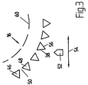
- the mechanical cleaning device identified by the reference number 16 in FIG. 1 in the form of a slotted screen 16 is shown enlarged in the detail in FIG. 3.
- the mechanical Cleaning device 16 comprises mutually spaced triangular sections Profile elements 46, 48, between which gaps 50 run.
- the profile elements 46, 48 are arranged in such a way that their tips face away from the surface, ie in the direction of the container 14 run.
- a spray device 52 On the container side, that is along the underside of the slotted screen 16, there is a spray device 52 arranged, which can be moved along the underside of the slotted screen 16 (double arrow 54) or is pivotable in order to dispense liquid from the spray device 42 onto the gaps 50 align, which ensures that existing dirt deposits in this area or those in the area of the lower legs 56, 58 of the profile elements 46, 48 can be removed.
- the spray device 52 which can be spray lances or spray pipes, but also a full-coverage spray device that runs almost entirely along the The underside of the cleaning device 16 extends, is conceivable - can also be removed from the container 14 withdrawn water can be supplied. Alternatively or in addition, there is also Possibility to connect the spray device 52 to a fresh water connection.
- the arrangement according to FIG. 1 itself now works as follows. Polluted water overflows the line 34 in the sludge trap 12. Care should be taken that in the sludge trap 12 a minimum amount of liquid has been accumulated so that via the slurry pump 22 no substances deposited on the liquid surface 38 can be sucked in; because in the event that the pump 22 would deliver oil or gasoline and water, would result in an emulsion in the container 14, so that a further use of the cleaned Water for the car wash 10 was out of the question.
- the level regulation in the Sludge trap 12, that is to say the liquid surface 38 should take place in such a way that level differences from a maximum of 10 to 25%.
- the bottom area 20 of the sludge trap 12 is taken up by the cleaned waste water Container 14 with water enriched with ozone introduced via line 26.
- the wastewater is mixed intensively in the bottom region 20 with the water containing ozone in such a way that the organic constituents are oxidized, i.e. degraded can.
- Any excess oil or petrol that is contained is separated due to the Difference in density to the water in the area of the surface 38 and can also by Ozone input are gradually reduced. This can be done in particular if the washing system 10 is out of operation and liquid in the circuit via the pump 22, the first line 24, the container 14 and the line connected to the ozone generator 18 26 flows in the circuit.
- the water pretreated in the sludge trap 12 is mentioned at the lowest point removed, always ensuring that there is sufficient liquid in the sludge trap 12 is present, on the one hand to ensure effectiveness as an oil separator, and on the other hand to prevent sludge from settling on the bottom. Thus the formation of Digested sludge excluded.
- the UV radiation source 44 can be arranged so that ozone is still present of UV light can be destroyed.
- the line 24 can be transparent Have section that is surrounded by UV light sources.
- can cover 60 such as splash guard above the slotted screen 16 be arranged.
- FIG. 2 is a particularly preferred further embodiment of an arrangement for Treatment of waste water, in particular from a car wash remove, with elements that have been used in Fig. 1, the same reference numerals exhibit.
- the method steps according to FIG. 1 also apply largely with restrictions for the domestic water to be drained.
- Waste water supplied to the consumer such as a car wash system 10 is provided according to FIG. 2, that the treated wastewater a can 62 as a second cleaning stage is removed, which is arranged in a circuit 64 which via a line 66, the is referred to as the fourth line from which sludge trap 12 is supplied with water.
- the treated wastewater a can 62 as a second cleaning stage is removed, which is arranged in a circuit 64 which via a line 66, the is referred to as the fourth line from which sludge trap 12 is supplied with water.
- the unit 68 can also be arranged outside the sludge trap 12, however, the suction point in the bottom area 22 opens.
- the circuit 64 containing the can 62 in turn has another Conveyor unit 70 so that liquid with the required speed and Derchatz flows through the can 62.
- a branch 72 flows from the circuit 64 behind the can 62 from which opens into the bottom region 20 of the sludge trap 12. So that the branch 72 of Liquid flows through, can be arranged behind the branch from the circuit 64 Throttle element 74 can be provided in the circuit 64. Since the throttle body (74) is used Setting the pressure conditions in the can and in the line (72).
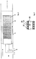
- the basic structure of the can 62 is shown in FIGS. 4 and 5.
- the can 62 consists of an outer tube 76, within and coaxially with this an inner tube 78 is arranged so that an annular space 80 is formed between the inner and outer tubes, which is traversed by liquid coming from the circuit 74.
- the inner tube 78 consists of a wound triangular wire 82 with a cross section an isosceles triangle, the edge lengths 84 preferably about 1 mm and the Distance between adjacent sections of the wire 82 so the column 86 a Has a width of about 30 microns.
- the tip of the wire 82 points to the axis of the inner tube 78.
- the triangular wire 82 is wound on rods 88 running in the longitudinal direction and with welded this.
- the can 62 in particular the inner tube 78, can have a length of 0.5 to 3 m.
- the inner diameter of the outer tube 76 can e.g. approx. 60-270 mm and the outside diameter of the inner tube 78 be approx. 50-250 mm.
- the liquid entering the annular space 80 experiences due to the formation of the can and its dimensioning a strong cross-flow in such a way that essentially do not clog columns 86. Sufficient separation takes place of solids in such a way that those entering the interior 90 of the inner tube 78 Liquid is extremely clean, so that it flows to the consumer 10 via a line 92 can be supplied.
- a compressed air line 94 opens into the interior 90 of the inner tube 78 by a pulse-like compressed air injection, possibly in columns 86 To remove deposits.
- water can flow from the interior 90 toward the Annulus 80 are pressed, which also cleaning takes place.
- a UV radiation source can be provided to ensure that the respective cleaning device no water enriched with ozone is supplied.
- process water volumes of 50 m 3 per hour and more can be taken from the canned pipe 62, taking into account the dimensioning of the canned pipe 62 given above, the throughput through the inner pipe being only about 5 to 20% of that Corresponding can 62 penetrating liquid and flowing through the circuit 64 corresponds.
- process water supplied to the consumer 10 only contains dirt particles of a size of up to 20 mm.
Landscapes
- Life Sciences & Earth Sciences (AREA)
- Hydrology & Water Resources (AREA)
- Engineering & Computer Science (AREA)
- Environmental & Geological Engineering (AREA)
- Water Supply & Treatment (AREA)
- Chemical & Material Sciences (AREA)
- Organic Chemistry (AREA)
- Treatment Of Water By Oxidation Or Reduction (AREA)
- Physical Water Treatments (AREA)
Abstract
Description
- Fig. 1
- eine Prinzipdarstellung einer ersten Ausführungsfrom einer Anordnung zur Aufbereitung von Abwasser,
- Fig. 2
- eine Prinzpdarstellung einer zweiten Ausführungsform einer Anordnung zur Aufbereitung von Abwasser,
- Fig. 3
- eine Detaildarstellung einer ersten mechanischen Reinigungseinrichtung der Fig. 1 und 2,
- Fig. 4
- eine Prinzipdarstellung einer zweiten mechanischen Reinigungseinrichtung der Fig. 2 und
- Fig. 5
- ein Ausschnitt der Reinigungseinrichtung nach Fig. 4.
Claims (12)
- Anordnung zum Reinigen von bei einem Verbraucher (10) wie insbesondere einer PKW-Waschanlage anfallendem Abwasser umfassend einen das Abwasser aufnehmenden ersten Behälter (12), zumindest einen gereinigtes bzw. vorgereinigtes Abwasser aufnehmenden zweiten Behälter (14), zumindest eine dem zweiten Behälter vorgeschaltete erste Reinigungseinrichtung (16) für das Abwasser, gegebenenfalls eine Einrichtung (18) zum Erzeugen von Ozon zum Behandeln von Abwasser sowie zumindest ein erstes Förderaggregat (22) zum Fördern des Abwassers, wobei das in dem zweiten Behälter (14) angesammelte gereinigte bzw. vorgereinigte Abwasser unmittelbar oder mittelbar dem Verbraucher wieder zuführbar ist,
dadurch gekennzeichnet,
dass das erste Förderaggregat (22) oder eine Ansaugstelle dieses im Bodenbereich (20) des ersten Behälters (12) angeordnet ist, dass von dem ersten Förderaggregat eine zu der Reinigungseinrichtung (16) führende erste Leitung (24) ausgeht, von der zumindest vorgereinigtes Abwasser in den zweiten Behälter (14) gelangt, dass von dem zweiten Behälter eine in den Bodenbereich des ersten Behälters führende zweite Leitung (26) ausgeht, dass von dem zweiten Behälter eine dritte zu dem Verbraucher (10) führende Leitung (30) und/oder von dem ersten Behälter eine vierte Leitung (66) ausgeht, die in einem eine zweite Reinigungseinrichtung (62) aufweisenden Kreislauf (64) mündet, wobei von der zweiten Reinigungseinrichtung eine gereinigtes Wasser abführende fünfte Leitung (92) zu dem Verbraucher (10) führt. - Anordnung nach Anspruch 1,
dadurch gekennzeichnet,
dass die erste Reinigungseinrichtung (16) ein Filter wie Spaltsieb und/oder die zweite Reinigungseinrichtung (62) ein Spaltrohr ist. - Anordnung nach Anspruch 2,
dadurch gekennzeichnet,
dass das Spaltrohr (62) aus einem mit der zu dem Verbraucher (10) führenden fünften Leitung (92) verbundenen Innenraum (90) umgebendes aus gewickeltem Draht wie Dreikantdraht (82) bestehendes flüssigkeitsdurchlässiges Innenrohr (78) und einem dieses umgebenden umfangsseitig geschlossenes Außenrohr (76) besteht, wobei zwischen Innen- und Außenrohr vorhandener Ringraum (80) mit dem Kreislauf (64) verbunden ist. - Anordnung nach zumindest einem der vorhergehenden Ansprüche,
dadurch gekennzeichnet,
dass unterhalb der ersten zueinander beabstandete vorzugsweise im Schnitt dreieckförmige Profilelemente wie -stäbe (46, 48) umfassenden ein Spaltsieb bildenden Reinigungseinrichtung (16) eine auf deren Profilelemente ausgerichtete Sprühreinrichtung angeordnet ist, die vorzugsweise entlang von der Reinigungseinrichtung aufgespannter Fläche verfahrbar und/oder verschwenkbar ausgebildet ist, und/oder dass das Innenrohr (78) des Spaltrohrs (62) von seinem Innenraum (90) her insbesondere impulsartig mit Druckluft und/oder Flüssigkeit beaufschlagbar ist. - Anordnung nach zumindest einem der vorhergehenden Ansprüche,
dadurch gekennzeichnet,
dass von dem ein Förderaggregat (70) aufweisenden Kreislauf (64) ein zu dem ersten Behälter (12) führender Abzweig (72) ausgeht. - Anordnung nach zumindest einem der vorhergehenden Ansprüche,
dadurch gekennzeichnet,
dass der erste Behälter (12) mit einer Mindestmenge an Abwasser und/oder zumindest vorgereinigtem Abwasser und/oder gereinigtem Abwasser derart gefüllt ist, dass ein Absaugen von auf dem in dem ersten Behälter vorhandenen Abwasser gesammelten Schmutzstoffen durch das erste Förderaggregat (22) unterbleibt. - Anordnung nach zumindest einem der vorhergehenden Ansprüche,
dadurch gekennzeichnet,
dass die den zweiten Behälter (14) mit dem ersten Behälter (12) verbindende zweite Leitung (26) mit der Ozon erzeugenden Einrichtung (18) verbindbar ist. - Anordnung nach zumindest einem der vorhergehenden Ansprüche,
dadurch gekennzeichnet,
dass der zu der ersten Reinigungseinrichtung (16) führenden ersten Leitung (24) und/oder der zu dem Kreislauf (64) führenden vierten Leitung und/oder dem Kreislauf eine jeweilige Leitung vorzugsweise ganz oder teilweise umgebende UV-Strahlungsquelle (44) zugeordnet ist. - Anordnung nach zumindest einem der vorhergehenden Ansprüche,
dadurch gekennzeichnet,
dass das von dem Verbraucher (10) kommende Abwasser oberhalb oder knapp unterhalb des Flüssigkeitsspiegels (38) in den ersten Behälter (12) insbesondere beruhigt einleitbar ist, wobei insbesondere der erste Behälter mit einer Schwankungsbreite von etwa ± 15 % mit Flüssigkeit gefüllt ist. - Anordnung nach zumindest einem der vorhergehenden Ansprüche,
dadurch gekennzeichnet,
dass der zwischen dem Außen- und Innenrohr (76, 78) des Spaltrohrs (62) vorhandene Ringraum (80) derart ausgebildet ist und/oder der Kreislauf (64) in diesen derart mündet, dass die den Ringraum durchströmende Flüssigkeit einer starken Querströmung ausgesetzt ist. - Anordnung nach zumindest einem der vorhergehenden Ansprüche,
dadurch gekennzeichnet,
dass das Innenrohr (78) einen von der Flüssigkeit durchströmten Spalt (86) einer Breite derart aufweist, dass 5 - 20 %, insbesondere 5 - 10 % der dem Spaltrohr (62) zugeführten Flüssigkeit über den Innenraum (90) des Innenrohrs (78) gelangende zu dem Verbraucher (10) strömen. - Anordnung nach zumindest einem der vorhergehenden Ansprüche,
dadurch gekennzeichnet,
dass in der zu dem Verbraucher (10) führenden fünften Leitung (92) ein Strömungswiderstand derart aufgebaut ist, dass zwischen Eintritt in den Innenraum (90) des Innenrohrs (78) und Austritt aus dem Innenraum eine Druckdifferenz von in etwa 0,05 bis 0,3 bar, insbesondere in etwa 0,1 bar herrscht.
Applications Claiming Priority (4)
| Application Number | Priority Date | Filing Date | Title |
|---|---|---|---|
| DE29722114U DE29722114U1 (de) | 1997-12-17 | 1997-12-17 | Anordnung zum Reinigen von Abwasser |
| DE29722114U | 1997-12-17 | ||
| DE29813706U DE29813706U1 (de) | 1998-07-31 | 1998-07-31 | Mechanische Reinigungseinrichtung |
| DE29813706U | 1998-07-31 |
Publications (2)
| Publication Number | Publication Date |
|---|---|
| EP0936191A2 true EP0936191A2 (de) | 1999-08-18 |
| EP0936191A3 EP0936191A3 (de) | 2001-11-21 |
Family
ID=26061008
Family Applications (1)
| Application Number | Title | Priority Date | Filing Date |
|---|---|---|---|
| EP98123864A Withdrawn EP0936191A3 (de) | 1997-12-17 | 1998-12-16 | Anordnung zum Reinigen von Abwasser |
Country Status (1)
| Country | Link |
|---|---|
| EP (1) | EP0936191A3 (de) |
Family Cites Families (4)
| Publication number | Priority date | Publication date | Assignee | Title |
|---|---|---|---|---|
| DE4040007A1 (de) * | 1990-12-14 | 1992-06-17 | Alfred Poppe | Selbstbedienungs-autowaschanlage |
| DE4238719A1 (de) * | 1992-11-17 | 1994-05-26 | Dornier Gmbh | Verfahren zur Abwasserbehandlung und Recycling der Abwässer in Kfz-Betriebswerkstätten |
| EP0567951A1 (de) * | 1992-04-25 | 1993-11-03 | Dornier Gmbh | Verfahren zur Behandlung und Rezyklierung der Abwässer von Kraftfahrzeug-Betriebswerkstätten |
| ES2114610T3 (es) * | 1992-07-03 | 1998-06-01 | Kaibel & Sieber Maschf Gmbh | Sistema y procedimiento para la depuracion de aguas residuales. |
-
1998
- 1998-12-16 EP EP98123864A patent/EP0936191A3/de not_active Withdrawn
Also Published As
| Publication number | Publication date |
|---|---|
| EP0936191A3 (de) | 2001-11-21 |
Similar Documents
| Publication | Publication Date | Title |
|---|---|---|
| DE60104188T2 (de) | Verfahren und vorrichtung zur behandlung von wasser/abwasser | |
| DE2753064A1 (de) | Verfahren zum absondern von verunreinigungen aus fluessigkeiten | |
| AT404933B (de) | Anordnung und verfahren zum reinigen von abwasser | |
| EP0592508B2 (de) | Verfahren und vorrichtung zur verbesserung der aufbereitung von abwasser-feststoffen, sand, müll oder dergleichen | |
| EP0436090B1 (de) | Verfahren zur Reinigung von Abwasser von Auto-Waschanlagen | |
| EP0657389A1 (de) | Verfahren und Vorrichtung zum biologischen Reinigen von Wasser | |
| DE3941673A1 (de) | Vorrichtung zum entfernen von sieb- und grobstoffen aus abwasser | |
| DE10204248B4 (de) | Filtereinrichtung für ein Vakuumtoilettensystem | |
| DE19533935C2 (de) | Vorrichtung für die Reinigung von Abwasser | |
| AT505926B1 (de) | Abwasserbehandlungsanlage und verfahren zum behandeln von abwasser | |
| DE69012281T2 (de) | Verfahren und vorrichtung vom typ des zirkulierenden filtermediums zur reinigung von verunreinigtem wasser. | |
| EP1927388A1 (de) | Regenwasser-Schachtfiltersystem | |
| DE102004009559A1 (de) | Membranbioreaktor und Verfahren zur Reinigung von Abwässern | |
| EP0105225B1 (de) | Verfahren zum Reinigen eines Flüssigkeitsfilters und einer dieses enthaltenden Abscheideranlage | |
| DE3325203A1 (de) | Druckreaktor | |
| DE19929568A1 (de) | Verfahren zur Wasseraufbereitung und Abwasserreinigung unter Verwendung eines Schwebefilterbettes | |
| DE29722114U1 (de) | Anordnung zum Reinigen von Abwasser | |
| DE20000966U1 (de) | Anlage zum Reinigen von Abwasser | |
| DE10119119B4 (de) | Verfahren zur Aufbereitung von Brauchwasser | |
| DE4013226C1 (de) | ||
| DE9400558U1 (de) | Einrichtung zur Aufbereitung von mit Reinigungsmitteln versehenem Schmutzwasser, insbesondere des Schmutzwassers einer Autowaschanlage | |
| DE29810474U1 (de) | Vorrichtung zum Eindicken von Schlämmen | |
| DE4305099C2 (de) | Verfahren zur Reinigung einer Filtereinrichtung und Filtereinrichtung zur Durchführung des Verfahrens | |
| DE19635005A1 (de) | Verfahren zum Aufbereiten von verunreinigtem Abwasser und Vorrichtung zu dessen Durchführung | |
| EP3872264B1 (de) | Mobile filtereinrichtung und verfahren zum filtern von verunreinigter flüssigkeit |
Legal Events
| Date | Code | Title | Description |
|---|---|---|---|
| PUAI | Public reference made under article 153(3) epc to a published international application that has entered the european phase |
Free format text: ORIGINAL CODE: 0009012 |
|
| AK | Designated contracting states |
Kind code of ref document: A2 Designated state(s): AT BE CH CY DE DK ES FI FR GB GR IE IT LI LU MC NL PT SE |
|
| AX | Request for extension of the european patent |
Free format text: AL;LT;LV;MK;RO;SI |
|
| PUAL | Search report despatched |
Free format text: ORIGINAL CODE: 0009013 |
|
| AK | Designated contracting states |
Kind code of ref document: A3 Designated state(s): AT BE CH CY DE DK ES FI FR GB GR IE IT LI LU MC NL PT SE |
|
| AX | Request for extension of the european patent |
Free format text: AL;LT;LV;MK;RO;SI |
|
| STAA | Information on the status of an ep patent application or granted ep patent |
Free format text: STATUS: THE APPLICATION IS DEEMED TO BE WITHDRAWN |
|
| 18D | Application deemed to be withdrawn |
Effective date: 20010701 |