EP0936301A2 - Appareil pour l' alimentation d' une suspension de fibres sur un dispositif d' essorage - Google Patents
Appareil pour l' alimentation d' une suspension de fibres sur un dispositif d' essorage Download PDFInfo
- Publication number
- EP0936301A2 EP0936301A2 EP98124784A EP98124784A EP0936301A2 EP 0936301 A2 EP0936301 A2 EP 0936301A2 EP 98124784 A EP98124784 A EP 98124784A EP 98124784 A EP98124784 A EP 98124784A EP 0936301 A2 EP0936301 A2 EP 0936301A2
- Authority
- EP
- European Patent Office
- Prior art keywords
- eccentric
- eccentric shaft
- adjustable
- partition
- layer
- Prior art date
- Legal status (The legal status is an assumption and is not a legal conclusion. Google has not performed a legal analysis and makes no representation as to the accuracy of the status listed.)
- Granted
Links
Images


Classifications
-
- D—TEXTILES; PAPER
- D21—PAPER-MAKING; PRODUCTION OF CELLULOSE
- D21F—PAPER-MAKING MACHINES; METHODS OF PRODUCING PAPER THEREON
- D21F1/00—Wet end of machines for making continuous webs of paper
- D21F1/02—Head boxes of Fourdrinier machines
-
- D—TEXTILES; PAPER
- D21—PAPER-MAKING; PRODUCTION OF CELLULOSE
- D21F—PAPER-MAKING MACHINES; METHODS OF PRODUCING PAPER THEREON
- D21F1/00—Wet end of machines for making continuous webs of paper
- D21F1/02—Head boxes of Fourdrinier machines
- D21F1/028—Details of the nozzle section
-
- D—TEXTILES; PAPER
- D21—PAPER-MAKING; PRODUCTION OF CELLULOSE
- D21F—PAPER-MAKING MACHINES; METHODS OF PRODUCING PAPER THEREON
- D21F9/00—Complete machines for making continuous webs of paper
- D21F9/003—Complete machines for making continuous webs of paper of the twin-wire type
- D21F9/006—Complete machines for making continuous webs of paper of the twin-wire type paper or board consisting of two or more layers
Definitions
- the invention relates to a device for supplying a fiber suspension to a dewatering device, in particular for a tissue machine.
- Devices of this type also called headbox
- regulation of the flow rate of the fiber suspension can practically only be achieved via the pressure.
- a different flow rate such as is required, for example, for different top and bottom qualities, cannot be achieved.
- the aim of the invention is therefore to improve the field of application and the control options for headboxes.
- the invention is therefore characterized in that one or more one-piece, wedge-shaped lamella tip (s) made of steel is or are provided for a two-layer or multi-layer headbox for separating the individual areas.
- This makes it possible to achieve a stable separation and thus also a constant setting of the outlet gap heights even at different inlet pressures, so that a differential speed can be set between the individual suspension flows.
- An advantageous development of the invention is characterized in that the lamella tip (s) are prestressed against the partition of the feed device by means of a tie rod. A particularly stable and therefore exact adjustment of the outlet gap heights is possible.
- a favorable embodiment of the invention is characterized in that the distance from the lower lip and / or upper lip to the slat tip is adjustable.
- An advantageous embodiment of the invention is characterized in that an eccentric shaft is provided for adjusting the height of the outlet gap between a minimum and maximum value. By adjusting the height of the outlet gap, the flow rate of the suspension stream can be adapted to the end product in accordance with the requirements.
- the use of an eccentric ensures a very precise adjustment of the outlet gap height.
- a favorable further development of the invention is characterized in that the upper lip can be adjusted by means of an eccentric, whereby alternatively or additionally the lower lip can be adjusted by means of an eccentric. The adjustment of the upper and / or lower lip enables the optimal conditions for regulating the flow rate of the individual layers, depending on the design as a two- or multi-layer headbox.
- a favorable embodiment of the invention is characterized in that a partition-lamella tip unit can be adjusted by means of an eccentric.
- An advantageous embodiment of the invention is characterized in that the eccentric shaft is supported several times over the width of the machine, wherein the support can take place at regular intervals.
- a favorable development of the invention is characterized in that the eccentric shaft is connected to a geared motor. This means that the outlet height and thus the flow rate of the fiber suspension can be adjusted or regulated accordingly, even during operation of the paper machine.
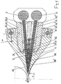
- FIG. 1 shows a device for supplying fiber suspensions to a dewatering device, in particular for a tissue machine, in the form of a two-layer headbox.
- the suspension is fed in simultaneously via two channels 1 transversely to the machine direction, then the flow direction of the suspension is 90 degrees redirected in the machine direction.
- the suspension is then passed through two turbulence generator chambers 2 into the outlet chambers 3, 4 designed as nozzle spaces, at the end of which it leaves the device and strikes the dewatering device.
- the two nozzle spaces 3, 4 are separated by a wall 8 which is prestressed against the supporting body 10 by means of drilled screws 9.
- the partition 8 At the outlet end of the partition 8 there is a one-piece, wedge-shaped lamella tip 12 made of stainless steel, which is prestressed against the partition 8 by means of tie rods 13.
- the partition 8 and the lamella tip 12 form a solid separating element between the two nozzle spaces 3, 4 in the assembled state. Due to its pretensioning relative to the supporting body 10, different operating pressures (up to 0.5 bar) and thus different flow rates of the fiber suspension in both are possible Use layers. For this purpose, it is necessary to set the outlet gap heights a and b of the two nozzle chambers 3, 4 differently. For this purpose, the upper lip 18 or lower lip 18 'are pivoted about the joints 14, 14'.
- This pivoting movement is carried out by an eccentric shaft 16, 16 ', which are supported over the machine width, at regular intervals in bearings 17, 17' on the rigid cover plates 20, 20 'of the device.
- the eccentricity e of the shafts allows the gap heights a and b to be set between a minimum and a maximum value.
- the construction is designed in such a way that even with constant rotation of the eccentric shaft 16, 16 'by a drive 22, the upper lip 18 and the lower lip 18' never come into contact with the lamella tip 12 and therefore no damage can occur.
- the contour angle ⁇ in the two-layer headbox is smaller than in the case of conventional adjustments using geared motors.
- FIG. 1a shows a detail of the outlet gap in FIG. 1. The different sizes of the outlet gaps a (nozzle space 3) and b (nozzle space 4) can be clearly seen here.
- the suspension simultaneously via three channels 1 transversely to the machine direction in the Vorrich device, then the flow direction of the suspension is deflected by 90 degrees in the machine direction.
- the suspension then flows through three turbulence generating chambers 2 into the nozzle chambers 3, 4, 5 called outlet chambers, at the end of which they leave the device and hit the dewatering machine.
- it is injected between two screens 24, 24 'which run around two rollers 25, 25'.
- the two nozzle spaces 4, 5 are separated by a wall 8, at the end of which there is a one-piece, wedge-shaped lamella tip 12 made of stainless steel.
- the partition 8 and the lamella tip 12 form a firm, non-adjustable separating element between the two nozzle spaces 4, 5. Its prestressing relative to the support body 10 enables differences of up to 0.5 bar and thus different flow rates of the fiber suspensions in to achieve two layers.
- the two nozzle spaces 3, 4 are separated by a partition 6, which is rotatably mounted about an axis 7.
- a partition 6 which is rotatably mounted about an axis 7.
- At the outlet-side end of the partition 6 there is also a one-piece lamella tip 12 'made of stainless steel, which is prestressed against the partition 6 by means of tie rods 11.
- the partition 6 and the lamella tip 12 'thus form a rigid separating element which, however, can be pivoted as a whole about the axis of rotation 7.
- This pivoting movement is carried out by an eccentric shaft 15, which are supported at regular intervals in bearings 19 on the rigid rear wall 23 of the device over the machine width.
- the eccentricity e makes it possible to set the outlet gap height c of the nozzle chamber 4 between a minimum and a maximum value and to fix it.
- the outlet gap heights a and b of the two nozzle chambers 3 and 5 can also be set and fixed between a minimum and maximum value.
- the upper lip 18 or lower lip 18 ' are pivoted about the joints 14, 14'.
- This pivoting movement is carried out by an eccentric shaft 1, 16 ', which are supported over the machine width at regular intervals in bearings 17, 17' on the rigid cover plates 20, 20 'of the device.
- the eccentricity e of the shafts 16, 16 ' enables the gap heights a and b to be set between a minimum and a maximum value.
- the construction is designed in such a way that even with constant rotation of the eccentric shafts 16, 16 'by a drive 22, the upper lip 18 and the lower lip 18' never come into contact with the lamella tips 12, 12 'and therefore no damage can occur. This also applies to all positions of the movable partition 6 with lamella tip 12 '.
- the contour angle ⁇ in the three-layer headbox is smaller than in the case of conventional adjustments using geared motors.
- FIG. 2a shows a detail of the outlet gap in FIG. 2.
- the different settings of the outlet gap heights a (nozzle chamber 3), b (nozzle chamber 5) and c (nozzle chamber 4) can be seen.
- Fig. 3 shows a section along line III-III in Fig. 1 and analogously in Fig. 2.
- the eccentric shaft 16 is shown, which is supported several times over the machine width in bearings 17.
- a geared motor 22 is also shown, with which the gap height of the outlet gap can be adjusted.
- the invention is not restricted to the examples shown. Other types of lip adjustment can also be provided.
Landscapes
- Paper (AREA)
- Preliminary Treatment Of Fibers (AREA)
Applications Claiming Priority (2)
| Application Number | Priority Date | Filing Date | Title |
|---|---|---|---|
| AT0020698A AT406171B (de) | 1998-02-05 | 1998-02-05 | Vorrichtung zur zufuhr einer faserstoffsuspension auf eine entwässerungseinrichtung |
| AT20698 | 1998-02-05 |
Publications (3)
| Publication Number | Publication Date |
|---|---|
| EP0936301A2 true EP0936301A2 (fr) | 1999-08-18 |
| EP0936301A3 EP0936301A3 (fr) | 2000-02-23 |
| EP0936301B1 EP0936301B1 (fr) | 2003-11-26 |
Family
ID=3484304
Family Applications (1)
| Application Number | Title | Priority Date | Filing Date |
|---|---|---|---|
| EP98124784A Expired - Lifetime EP0936301B1 (fr) | 1998-02-05 | 1998-12-29 | Appareil pour l' alimentation d' une suspension de fibres sur un dispositif d' essorage |
Country Status (6)
| Country | Link |
|---|---|
| US (1) | US6368464B1 (fr) |
| EP (1) | EP0936301B1 (fr) |
| AT (1) | AT406171B (fr) |
| BR (1) | BR9900531A (fr) |
| DE (1) | DE59810270D1 (fr) |
| ES (1) | ES2210654T3 (fr) |
Family Cites Families (11)
| Publication number | Priority date | Publication date | Assignee | Title |
|---|---|---|---|---|
| US2615374A (en) * | 1948-10-04 | 1952-10-28 | Dominion Eng Works Ltd | Slice assembly for papermaking machines |
| SE7707981L (sv) * | 1976-12-02 | 1978-06-03 | Ahlstroem Dev Gmbh | Anordning for paverkan av ett banformigt material |
| FI58364C (fi) * | 1977-07-13 | 1981-01-12 | Tampella Oy Ab | Matningsanordning foer en banformningsmaskin foer framstaellning av en tvao- eller flerskiktig fiberbana |
| DE3010730C2 (de) * | 1980-03-20 | 1983-01-05 | J.M. Voith Gmbh, 7920 Heidenheim | Stoffauflauf für eine Papiermaschine |
| DE3348218C2 (fr) * | 1983-06-09 | 1990-05-10 | Sulzer-Escher Wyss Gmbh, 7980 Ravensburg, De | |
| CH672515A5 (fr) * | 1987-02-02 | 1989-11-30 | Escher Wyss Gmbh | |
| DE3807629A1 (de) * | 1988-03-09 | 1989-09-21 | Escher Wyss Gmbh | Vorrichtung zum halten einer trennlamelle |
| EP0681057B1 (fr) * | 1994-04-29 | 2002-08-28 | Voith Paper Patent GmbH | Caisse de tête à plusieurs couches |
| DE4440079C2 (de) * | 1994-11-10 | 1997-10-02 | Voith Sulzer Papiermasch Gmbh | Mehrschichten-Stoffauflauf |
| DE19652982A1 (de) * | 1996-12-19 | 1997-05-22 | Voith Sulzer Papiermasch Gmbh | Lösbare Verbindungsvorrichtung zum Trennelement eines Mehrschichtenstoffauflaufes |
| DE19652983A1 (de) * | 1996-12-19 | 1997-05-28 | Voith Sulzer Papiermasch Gmbh | Trennelement eines Mehrschichtenstoffauflaufes |
-
1998
- 1998-02-05 AT AT0020698A patent/AT406171B/de not_active IP Right Cessation
- 1998-12-29 EP EP98124784A patent/EP0936301B1/fr not_active Expired - Lifetime
- 1998-12-29 ES ES98124784T patent/ES2210654T3/es not_active Expired - Lifetime
- 1998-12-29 DE DE59810270T patent/DE59810270D1/de not_active Expired - Lifetime
-
1999
- 1999-02-04 BR BR9900531-0A patent/BR9900531A/pt not_active IP Right Cessation
- 1999-02-05 US US09/245,542 patent/US6368464B1/en not_active Expired - Lifetime
Also Published As
| Publication number | Publication date |
|---|---|
| AT406171B (de) | 2000-03-27 |
| BR9900531A (pt) | 2000-02-22 |
| US6368464B1 (en) | 2002-04-09 |
| DE59810270D1 (de) | 2004-01-08 |
| EP0936301B1 (fr) | 2003-11-26 |
| EP0936301A3 (fr) | 2000-02-23 |
| ATA20698A (de) | 1999-07-15 |
| ES2210654T3 (es) | 2004-07-01 |
Similar Documents
| Publication | Publication Date | Title |
|---|---|---|
| DE3514554C2 (de) | Stoffauflauf-Vorrichtung für eine Papiermaschine und Verfahren zu deren Betrieb | |
| DE3741603C2 (fr) | ||
| DE2824608C2 (de) | Stoffauflauf für eine Papiermaschine | |
| DE2509349C2 (de) | Vorrichtung zum Verdichten und Waschen oder dgl. einer Faserbreisuspension | |
| EP0711869A2 (fr) | Caisse de tête à plusieurs couches | |
| DE3321406C2 (fr) | ||
| EP0581051A1 (fr) | Caisse de tête à plusieurs couches pour une machine à papier ou analogue | |
| WO2010069652A1 (fr) | Caisson de tête pour machine de fabrication d'une bande de matière fibreuse | |
| EP0639239B1 (fr) | Systeme permettant d'influer sur la vitesse de jet dans une caisse de tete pour application de plusieurs couches | |
| DE3126460A1 (de) | Stoffauflaufvorrichtung fuer eine papiermaschine | |
| EP2531645A1 (fr) | Caisse de tête pour une machine de production d'une bande de matière fibreuse | |
| DE3109227C2 (de) | Stoffaustrittsschlitz für den Stoffauslauf von Papiermaschinen | |
| DE2537079A1 (de) | Stuetzanordnung fuer die feineinstellung des oberlippenteils des stoffauflaufkastens in einer papiermaschine oder dergleichen | |
| DE2607822A1 (de) | Stoffauflaufvorrichtung einer papiermaschine | |
| EP0936302B1 (fr) | Appareil pour l' alimentation d' une suspension de fibres sur un dispositif d' essorage | |
| DE2800547B2 (de) | Stoffauflauf für Papiermaschinen | |
| DE4328997C2 (de) | Naßpartie eines Doppelsieb-GAP-Formers | |
| DE1294803B (de) | Stoffauflaufkasten fuer Papiermaschinen | |
| EP0945385B1 (fr) | Triangle plieur d'un appareil de pliage d'une machine d'impression rotative | |
| EP0936301A2 (fr) | Appareil pour l' alimentation d' une suspension de fibres sur un dispositif d' essorage | |
| EP1489224A1 (fr) | Caisse de tête | |
| DE2622046A1 (de) | Vliesformeinrichtung fuer papiermaschinen mit siebformwalze | |
| DE3639823C2 (fr) | ||
| DE69726294T2 (de) | Geneigter unterfilz flachformer zur herstellung von einzel- oder mehrlagigen papieren | |
| DE4029545A1 (de) | Stoffauflauf-einrichtung |
Legal Events
| Date | Code | Title | Description |
|---|---|---|---|
| PUAI | Public reference made under article 153(3) epc to a published international application that has entered the european phase |
Free format text: ORIGINAL CODE: 0009012 |
|
| AK | Designated contracting states |
Kind code of ref document: A2 Designated state(s): CH DE ES FI FR GB IT LI SE |
|
| AX | Request for extension of the european patent |
Free format text: AL;LT;LV;MK;RO;SI |
|
| PUAL | Search report despatched |
Free format text: ORIGINAL CODE: 0009013 |
|
| AK | Designated contracting states |
Kind code of ref document: A3 Designated state(s): AT BE CH CY DE DK ES FI FR GB GR IE IT LI LU MC NL PT SE |
|
| AX | Request for extension of the european patent |
Free format text: AL;LT;LV;MK;RO;SI |
|
| 17P | Request for examination filed |
Effective date: 20000317 |
|
| RAP1 | Party data changed (applicant data changed or rights of an application transferred) |
Owner name: ANDRITZ AG |
|
| AKX | Designation fees paid |
Free format text: CH DE ES FI FR GB IT LI SE |
|
| 17Q | First examination report despatched |
Effective date: 20020115 |
|
| GRAH | Despatch of communication of intention to grant a patent |
Free format text: ORIGINAL CODE: EPIDOS IGRA |
|
| GRAS | Grant fee paid |
Free format text: ORIGINAL CODE: EPIDOSNIGR3 |
|
| GRAA | (expected) grant |
Free format text: ORIGINAL CODE: 0009210 |
|
| AK | Designated contracting states |
Kind code of ref document: B1 Designated state(s): CH DE ES FI FR GB IT LI SE |
|
| PG25 | Lapsed in a contracting state [announced via postgrant information from national office to epo] |
Ref country code: FR Free format text: LAPSE BECAUSE OF FAILURE TO SUBMIT A TRANSLATION OF THE DESCRIPTION OR TO PAY THE FEE WITHIN THE PRESCRIBED TIME-LIMIT Effective date: 20031126 |
|
| REG | Reference to a national code |
Ref country code: GB Ref legal event code: FG4D Free format text: NOT ENGLISH |
|
| REG | Reference to a national code |
Ref country code: CH Ref legal event code: EP |
|
| PG25 | Lapsed in a contracting state [announced via postgrant information from national office to epo] |
Ref country code: LI Free format text: LAPSE BECAUSE OF NON-PAYMENT OF DUE FEES Effective date: 20031231 Ref country code: CH Free format text: LAPSE BECAUSE OF NON-PAYMENT OF DUE FEES Effective date: 20031231 |
|
| REF | Corresponds to: |
Ref document number: 59810270 Country of ref document: DE Date of ref document: 20040108 Kind code of ref document: P |
|
| PGFP | Annual fee paid to national office [announced via postgrant information from national office to epo] |
Ref country code: FR Payment date: 20040116 Year of fee payment: 6 |
|
| REG | Reference to a national code |
Ref country code: SE Ref legal event code: TRGR |
|
| GBT | Gb: translation of ep patent filed (gb section 77(6)(a)/1977) |
Effective date: 20040223 |
|
| REG | Reference to a national code |
Ref country code: ES Ref legal event code: FG2A Ref document number: 2210654 Country of ref document: ES Kind code of ref document: T3 |
|
| REG | Reference to a national code |
Ref country code: CH Ref legal event code: PL |
|
| PLBE | No opposition filed within time limit |
Free format text: ORIGINAL CODE: 0009261 |
|
| STAA | Information on the status of an ep patent application or granted ep patent |
Free format text: STATUS: NO OPPOSITION FILED WITHIN TIME LIMIT |
|
| 26N | No opposition filed |
Effective date: 20040827 |
|
| EN | Fr: translation not filed | ||
| PGFP | Annual fee paid to national office [announced via postgrant information from national office to epo] |
Ref country code: GB Payment date: 20101221 Year of fee payment: 13 |
|
| PGFP | Annual fee paid to national office [announced via postgrant information from national office to epo] |
Ref country code: FI Payment date: 20111214 Year of fee payment: 14 Ref country code: ES Payment date: 20111227 Year of fee payment: 14 |
|
| PGFP | Annual fee paid to national office [announced via postgrant information from national office to epo] |
Ref country code: DE Payment date: 20111222 Year of fee payment: 14 |
|
| PGFP | Annual fee paid to national office [announced via postgrant information from national office to epo] |
Ref country code: IT Payment date: 20111227 Year of fee payment: 14 |
|
| GBPC | Gb: european patent ceased through non-payment of renewal fee |
Effective date: 20121229 |
|
| PG25 | Lapsed in a contracting state [announced via postgrant information from national office to epo] |
Ref country code: FI Free format text: LAPSE BECAUSE OF NON-PAYMENT OF DUE FEES Effective date: 20121229 |
|
| REG | Reference to a national code |
Ref country code: DE Ref legal event code: R119 Ref document number: 59810270 Country of ref document: DE Effective date: 20130702 |
|
| PG25 | Lapsed in a contracting state [announced via postgrant information from national office to epo] |
Ref country code: DE Free format text: LAPSE BECAUSE OF NON-PAYMENT OF DUE FEES Effective date: 20130702 |
|
| PG25 | Lapsed in a contracting state [announced via postgrant information from national office to epo] |
Ref country code: GB Free format text: LAPSE BECAUSE OF NON-PAYMENT OF DUE FEES Effective date: 20121229 |
|
| PG25 | Lapsed in a contracting state [announced via postgrant information from national office to epo] |
Ref country code: IT Free format text: LAPSE BECAUSE OF NON-PAYMENT OF DUE FEES Effective date: 20121229 |
|
| PGFP | Annual fee paid to national office [announced via postgrant information from national office to epo] |
Ref country code: SE Payment date: 20131219 Year of fee payment: 16 |
|
| REG | Reference to a national code |
Ref country code: ES Ref legal event code: FD2A Effective date: 20140307 |
|
| PG25 | Lapsed in a contracting state [announced via postgrant information from national office to epo] |
Ref country code: ES Free format text: LAPSE BECAUSE OF NON-PAYMENT OF DUE FEES Effective date: 20121230 |
|
| PG25 | Lapsed in a contracting state [announced via postgrant information from national office to epo] |
Ref country code: SE Free format text: LAPSE BECAUSE OF NON-PAYMENT OF DUE FEES Effective date: 20141230 |
|
| REG | Reference to a national code |
Ref country code: SE Ref legal event code: EUG |