EP0936319A2 - Reinigungskörper für Rohrleitungen und Kanalisationssysteme - Google Patents
Reinigungskörper für Rohrleitungen und Kanalisationssysteme Download PDFInfo
- Publication number
- EP0936319A2 EP0936319A2 EP99102320A EP99102320A EP0936319A2 EP 0936319 A2 EP0936319 A2 EP 0936319A2 EP 99102320 A EP99102320 A EP 99102320A EP 99102320 A EP99102320 A EP 99102320A EP 0936319 A2 EP0936319 A2 EP 0936319A2
- Authority
- EP
- European Patent Office
- Prior art keywords
- pressurized water
- cleaning
- water
- channels
- pipes
- Prior art date
- Legal status (The legal status is an assumption and is not a legal conclusion. Google has not performed a legal analysis and makes no representation as to the accuracy of the status listed.)
- Granted
Links
- 238000004140 cleaning Methods 0.000 title claims abstract description 43
- XLYOFNOQVPJJNP-UHFFFAOYSA-N water Substances O XLYOFNOQVPJJNP-UHFFFAOYSA-N 0.000 claims abstract description 62
- 238000005192 partition Methods 0.000 claims description 6
- 239000000463 material Substances 0.000 claims description 4
- 239000007769 metal material Substances 0.000 claims description 3
- 230000003014 reinforcing effect Effects 0.000 claims description 3
- 230000000087 stabilizing effect Effects 0.000 claims description 3
- 230000007704 transition Effects 0.000 claims description 3
- JEIPFZHSYJVQDO-UHFFFAOYSA-N iron(III) oxide Inorganic materials O=[Fe]O[Fe]=O JEIPFZHSYJVQDO-UHFFFAOYSA-N 0.000 claims description 2
- 239000010865 sewage Substances 0.000 abstract description 2
- 230000000694 effects Effects 0.000 description 7
- 238000004519 manufacturing process Methods 0.000 description 5
- 238000004062 sedimentation Methods 0.000 description 4
- 238000005266 casting Methods 0.000 description 3
- 239000000919 ceramic Substances 0.000 description 3
- 238000000034 method Methods 0.000 description 3
- 239000004576 sand Substances 0.000 description 3
- 239000007787 solid Substances 0.000 description 3
- 239000002351 wastewater Substances 0.000 description 3
- 230000015572 biosynthetic process Effects 0.000 description 2
- 238000009826 distribution Methods 0.000 description 2
- 238000005495 investment casting Methods 0.000 description 2
- 239000008237 rinsing water Substances 0.000 description 2
- 239000013049 sediment Substances 0.000 description 2
- 239000011343 solid material Substances 0.000 description 2
- 206010010774 Constipation Diseases 0.000 description 1
- 230000002411 adverse Effects 0.000 description 1
- 239000000956 alloy Substances 0.000 description 1
- 229910045601 alloy Inorganic materials 0.000 description 1
- 230000009286 beneficial effect Effects 0.000 description 1
- 239000011230 binding agent Substances 0.000 description 1
- 238000005422 blasting Methods 0.000 description 1
- 239000011248 coating agent Substances 0.000 description 1
- 238000000576 coating method Methods 0.000 description 1
- 239000000356 contaminant Substances 0.000 description 1
- 238000005520 cutting process Methods 0.000 description 1
- 230000002349 favourable effect Effects 0.000 description 1
- 239000012530 fluid Substances 0.000 description 1
- 238000011010 flushing procedure Methods 0.000 description 1
- 239000007788 liquid Substances 0.000 description 1
- 230000007257 malfunction Effects 0.000 description 1
- 239000002184 metal Substances 0.000 description 1
- 238000003801 milling Methods 0.000 description 1
- 238000012805 post-processing Methods 0.000 description 1
- 238000012545 processing Methods 0.000 description 1
- 230000005855 radiation Effects 0.000 description 1
- 239000007921 spray Substances 0.000 description 1
- 230000003319 supportive effect Effects 0.000 description 1
- 239000000725 suspension Substances 0.000 description 1
- 229910052845 zircon Inorganic materials 0.000 description 1
- GFQYVLUOOAAOGM-UHFFFAOYSA-N zirconium(iv) silicate Chemical compound [Zr+4].[O-][Si]([O-])([O-])[O-] GFQYVLUOOAAOGM-UHFFFAOYSA-N 0.000 description 1
Images




Classifications
-
- E—FIXED CONSTRUCTIONS
- E03—WATER SUPPLY; SEWERAGE
- E03F—SEWERS; CESSPOOLS
- E03F9/00—Arrangements or fixed installations methods or devices for cleaning or clearing sewer pipes, e.g. by flushing
-
- B—PERFORMING OPERATIONS; TRANSPORTING
- B08—CLEANING
- B08B—CLEANING IN GENERAL; PREVENTION OF FOULING IN GENERAL
- B08B9/00—Cleaning hollow articles by methods or apparatus specially adapted thereto
- B08B9/02—Cleaning pipes or tubes or systems of pipes or tubes
- B08B9/027—Cleaning the internal surfaces; Removal of blockages
- B08B9/04—Cleaning the internal surfaces; Removal of blockages using cleaning devices introduced into and moved along the pipes
- B08B9/049—Cleaning the internal surfaces; Removal of blockages using cleaning devices introduced into and moved along the pipes having self-contained propelling means for moving the cleaning devices along the pipes, i.e. self-propelled
- B08B9/0495—Nozzles propelled by fluid jets
Definitions
- the invention relates to a cleaning body with pressurized water operation for difficult to access Cavities, especially for piping and sewer systems, in addition to the usual deposits also show strong sedimentation and incrustations.
- Wastewater pipe systems are known to be heavily laden with solids Flow media with low flow rate of constant danger of Exposed to constipation.
- cleaning devices for sewage pipes are well known and even in the most varied versions in the form of nozzles and / or movable ones Räumkörnemem with simultaneous pressure water or air flow with different efficiency in use.
- a device for the removal of sediments is named in DD-WP 226 028, the the sediments should dissolve and convey without additional pressure water supply.
- the mechanical removed in layers by a profile cleaning device designed as a hollow body Incrustations are whirled up using compressed air and against the direction of flow of the wastewater led into a trough-shaped space of the hollow body.
- a wastewater pump conducts this suspension, which contains different solids via a centrifuge to the outside. What is unsatisfactory here is that this device only for cleaning services in sewers with larger nominal diameter ranges is provided and due to the lack of clear water as an rinsing liquid, only an insufficient one Rough cleaning is achieved.
- DE-AS 24 27 278 there is also a device for cleaning sewers described, which from a longitudinally movable pressure pump in the sewer consists.
- This has a flexible suction nozzle on the inlet side and one on the outlet side the pressure hose connected to the pressure pump.
- the entire pressure pump is on mounted on a chassis, equipped with a centrifugal worm wheel and as explosion-proof Submersible thick matter pump.
- Another disadvantage of this device is the high outlay on equipment, the undesirable susceptibility to malfunction and the inadequate Effectiveness due to the lack of rinsing water and the insufficient pressure hose cross-section with suction.
- a cleaning device for pipes and pipes which is significantly improved in efficiency Channels are presented with DE-PS 195 16 780.
- This nozzle for propulsion and cleaning is in their round configuration is intended for hydrodynamic operation and consists of a nozzle body made of machined solid material, screwed together in two parts.
- the interior of this cleaning nozzle has elaborated cavities a pressurized water inlet opening, a distribution chamber, a conical water divider with adjacent channels and pressurized water outlet openings.
- the water divider disadvantageously contains a replaceable one Wear part in the form of a separate molded part.
- the aforementioned cleaning nozzle is also available in a further developed version DE-PS 195 33 654 become known. As also in a rounded configuration trained tool, this hydrodynamic nozzle is also not very suitable, mechanically supportive cleaning and clearing effects through the Break up sedimentation or other deposits or also Position tools or control systems in certain cavities.
- the undivided compact body manufactured using the precision casting process is required certain minimum cross sections of the cavities and outlet openings around the grains of sand the decayed ceramic forms, such as those used in investment casting, to be able to remove outside.
- Cast compact body for cleaning and clearing pipes and sewer systems is provided and at the same time tools and control systems if necessary can lead and position.
- This polygonal cast compact body has a pressurized water connection and points in the area the entry of pressurized water in a dome-shaped formation or in a division level a water divider with circular segment-shaped inlet openings.
- These entry openings are of knife-like partitions standing transversely to the direction of flow educated.
- pressurized water channels experience according to a defined number of outlet cross sections either a single or a multiple branch. Only immediately towards the end of the pressurized water channel, these pressurized water channels shrink without any flow resistance either in a given circular or slit-shaped Outlet cross-section.
- each a water divider with circular segment segments and circular segment-shaped inlet openings are advantageously in the area of the pressurized water inlet in several superimposed division levels.
- the edge-free and low flow resistance pressurized water channels form afterwards the water divider with the circular segment-shaped inlet openings a flowing Transition from the inlet cross section of the circular segment-shaped inlet openings into one Circular cross section. They are as large as possible from the central axis of the pressurized water inlet Deflection radius within the total volume of the polygonal cast compact in each given direction to the pressurized water inlet in each one above the other Pitch level guided symmetrically in pairs and without crossing.
- the pressurized water channel ends are designed according to the invention in outflow surfaces with cross sections of 0.2 mm 2 to 3 mm 2 .
- Cross sections of 1 mm 2 have proven to be favorable.
- the polygonal cast compact body as Original, undivided compact body with a cast or molded thread is designed for the pressurized water connection.
- a rust carrier and highly wear-resistant cast material which is practically mechanically hardly machinable.
- Sintered metallic or non-metallic materials have also proven themselves.
- a high level of stability is also guaranteed if the polygonal cast compact body as a shaped compact body has a shape that transitions into a rounded shape and contains reinforcing or stabilizing elements.
- Fig. 1 is a front view of an undivided polygonal cast compact body 1 made of rust-proof highly wear-resistant casting alloy G-X300CrMoB, which mechanically not or hardly postprocessable is shown.
- This undivided polygonal cast compact body 1 for hydraulic operation has on its underside a pressurized water connection 2 for along the Center axis 18 guided and entering in the flow direction 6 pressurized water and contains a total of eight outlet cross sections 11.
- the undivided polygonal cast compact body 1 which is based on the classic lost wax process using ceramic Molds were made extremely difficult and with high failure rates in a special, precise casting process using zircon sand cold hardening and hot box and graft cores with simultaneous use of special Binders made.
- Fig. 2 shows in longitudinal section AA the polygonal cast compact body 1 with the pressurized water inlet 16, which is bordered by a pre-cast thread 19.
- the outlet cross sections 11 at the pressurized water channel ends 13 of the pressurized water channels 8 each have an area size of 0.9 mm 2 .
- the pressurized water channels 8 connect in a division level 3 above the pressurized water inlet 16 without flow resistance.
- FIG. 3 and 4 each show the bottom view and the top view of the polygonal cast compact 1 recognize.
- the outlet cross sections are 11 of the pressurized water channels 8 recognizable. Shown from this direction is through the pressurized water connection 2 viewed at the pressurized water inlet 16, a water divider 4 with a segment of a circle Entry openings 5 arranged.
- the circular segment-shaped entry openings 5 of the water divider 4 are arranged transversely to the flow direction 6 knife-like partitions 7 formed. From Fig. 3 it can also be seen that the circular segment-shaped inlet openings 5 connect the pressurized water channels 8 without edges.
- section B-B of the polygonal cast compact body 1 in plan view of the parting plane 3, in which the water divider 4 with the transverse to the flow direction 6 standing knife-like partitions 7 formed circular segment-shaped Entry openings 5 is located.
- the eight cross sections of the pressurized water channels 8 recognizable.
- FIG. 6 shows the spatial representation of the pressurized water channels 8 in plan view of the branches 12 of the pressurized water channels 8, which then pass over the pressurized water channel ends 13 into the outlet cross sections 11 of 0.9 mm 2 outflow area in each case.
- FIG. 7 shows the spatial representation of the pressurized water channels 8 and the pressurized water inlet 16 with the pre-cast thread 19 shown in front view, to be seen is that the pressurized water channels 8 from the water divider 4 with the largest possible turning radius 10 are led to the pressurized water inlet 16.
- outlet cross sections 11 at the pressurized water channel ends 13 of the pressurized water channels 8 6 are alternately in FIG. 9 as a circular outlet cross section 14 and a slot-shaped outlet cross section 15 without any nozzle inserts. According to the intended field of application, the choice of arrangement is advantageous however also possible in a different assignment.
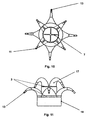
- Fig. 10 the bottom view of a water divider 4 is shown in two floors.
- Fig. 11 shows the side view of this water divider 4 with the parting planes 3 and the circular cross section 17 of the pressurized water channels 8 in two floors.
- FIG. 12 shows a particularly advantageous embodiment of a cleaning body with very high efficiency shown in front view.
- the pressurized water channels are 8 in the polygonal cast compact body 1 with the largest possible deflection radius 10 in each superimposed division level 3 in pairs symmetrically and without crossing arranged so that they over the total volume of the cleaning body extend the entire cross-section and thus an extremely low flow resistance Enable water flow with an effective cleaning, rinsing and clearing effect.
- Fig. 13 is the paired symmetrical and crossing-free routing of the pressurized water channels 8 shown in plan view.
- FIG. 14 A spatial representation of the polygonal cast compact body 1 is shown in FIG. 14 in multiple views.
- This polygonal cast compact body 1 was formed as a compact body without nozzle inserts also from sintered metal and in a further embodiment from a non-metallic Material, made of ceramic, manufactured and in practical use with good results tried. To increase the stability were reinforcing and stabilizing Elements with beneficial effects have been used.
- the advantages of the cleaning body according to the invention made of a material with extreme Wear resistance exists particularly in the postprocessing-free production method through a special casting process, which allows this cleaning body without replaceable wear parts, such as water divider segments or nozzle inserts, Economical to manufacture and as a single-use product after the signs of wear without separating out expensive repair work.
Landscapes
- Engineering & Computer Science (AREA)
- Health & Medical Sciences (AREA)
- Life Sciences & Earth Sciences (AREA)
- Hydrology & Water Resources (AREA)
- Public Health (AREA)
- Water Supply & Treatment (AREA)
- Mechanical Engineering (AREA)
- Nozzles (AREA)
- Cleaning In General (AREA)
- Sewage (AREA)
Abstract
Description
- Fig. 1:
- Vorderansicht des polygonalen Gußkompaktkörpers
- Fig. 2:
- Schnitt A-A des polygonalen Gußkompaktkörpers
- Fig. 3:
- Unteransicht des polygonalen Gußkompaktkörpers
- Fig. 4:
- Draufsicht des polygonalen Gußkompaktkörpers
- Fig. 5:
- Schnitt B-B des polygonalen Gußkompaktkörpers
- Fig. 6:
- räumliche Darstellung der Druckwasserkanäle in Draufsicht
- Fig. 7:
- räumliche Darstellung der Druckwasserkanäle in Vorderansicht
- Fig. 8 a:
- Vorderansicht eines Druckwasserkanals mit den Schnittstellen A-A, B-B, C-C und D-D
- Fig. 8 b:
- Querschnittsformen an den Schnittstellen A-A, B-B, C-C und D-D aus Fig. 8 a
- Fig. 9:
- Ausbildung der Austrittsquerschnitte
- Fig. 10:
- Unteransicht des Wasserteilers in zwei Etagen
- Fig. 11:
- Seitenansicht des Wasserteilers in zwei Etagen
- Fig. 12:
- Vorderansicht der paarweise symmetrisch und kreuzungsfreien Druckwasserkanalführung
- Fig. 13:
- Draufsicht auf die paarweise symmetrisch und kreuzungsfreie Druckwasserkanalführung
- Fig. 14:
- räumliche Darstellung des polygonalen Gußkompaktkörpers
- 1
- polygonaler Gußkompaktkörper
- 2
- Druckwasseranschluß
- 3
- Teilungsebene
- 4
- Wasserteiler
- 5
- kreissegmentförmige Eintrittsöffnung
- 6
- Strömungsrichtung
- 7
- messerartige Zwischenwände
- 8
- Druckwasserkanäle
- 9
- nahezu kreisförmiger Querschnitt
- 10
- größtmöglicher Umlenkradius
- 11
- Austrittsquerschnitte
- 12
- Verzweigung
- 13
- Druckwasserkanalende
- 14
- kreisförmiger Austrittsquerschnitt
- 15
- schlitzförmiger Austrittsquerschnitt
- 16
- Druckwassereintritt
- 17
- Kreisquerschnitt
- 18
- Mittelachse
- 19
- Gewinde
Claims (6)
- Reinigungskörper für Rohrleitungen und Kanalisationssysteme für Druckwasserbetrieb mit in seinem Inneren von der Mittelachse der Druckwasserzuführung im Umlenkradius im Bereich der Durchmesserhälfte entgegen der Vortriebsrichtung, seitlich oder nach vom geführten Wasserkanälen und an deren Enden befindlichen Reinigungsdüsen und Vortriebsdüsen, dadurch gekennzeichnet, daß ein reinigender und räumender und/oder Werkzeuge und/oder Kontrollsysteme führender polygonaler Gußkompaktkörper (1) mit Druckwasseranschluß (2) im Bereich des Druckwassereintritts (16) in einer kuppelförmigen Ausbildung oder in einer Teilungsebene (3) einen Wasserteiler (4) mit kreissegmentförmigen Eintrittsöffnungen (5) aufweist, die durch quer zur Strömungsrichtung (6) stehende messerartige Zwischenwände (7) gebildet sind und sich an die kreissegmentförmigen Eintrittsöffnungen (5) kantenfreie und strömunggswiderstandsarme Druckwasserkanäle (8) mit einem nahezu kreisförmigen Querschnitt (9) und einem größtmöglichen Umlenkradius (10) in beliebiger Richtung anschließen, die entsprechend einer festgelegten Anzahl von Austrittsquerschnitten (11) eine einfache oder mehrfache Verzweigung (12) erfahren, wobei sich die Druckwasserkanäle (8) erst unmittelbar gegen Druckwasserkanalende (13) jeweils in einen vorgegebenen kreisförmigen Austrittsquerschnitt (14) oder in einen vorgegebenen schlitzförmigen Austrittsquerschnitt (15) verkleinem.
- Reinigungskörper für Rohrleitungen und Kanalisationssysteme nach Anspruch 1, dadurch gekennzeichnet, daß im Bereich des Druckwassereintritts (16) in mehreren übereinanderliegenden Teilungsebenen (3) jeweils ein Wasserteiler (4) mit kreisringsegmentförmigen und kreissegmentförmigen Eintrittsöffnungen (5) angeordnet und eine dementsprechend vermehrte Anzahl an Druckwasserkanälen (8) mit einem größtmöglichen hydraulischen Durchmesser ausgebildet ist.
- Reinigungskörper für Rohrleitungen und Kanalisationssysteme nach Anspruch 1 und 2, dadurch gekennzeichnet, daß die kantenfreien und strömungswiderstandsarmen Druckwasserkanäle (8) im Anschluß an den Wasserteiler (4) mit den kreissegmentförmigen Eintrittsöffnungen (5) einen fließenden Übergang von dem Eintrittsquerschnitt der kreissegmentförmigen Eintrittsöffnungen (5) in einen Kreisquerschnitt (17) aufweisen und von der Mittelachse (18) des Druckwassereintritts (16) in einem größtmöglichen Umlenkradius (10) innerhalb des Gesamtvolumens des polygonalen Gußkompaktkörpers (1) in vorgegebener Richtung zum Druckwassereintritt (16) in jeder übereinanderliegenden Teilungsebene (3) paarweise symmetrisch und kreuzungsfrei geführt sind.
- Reinigungskörper für Rohrleitungen und Kanalisationssysteme nach Anspruch 1, dadurch gekennzeichnet, daß die vorgegebenen Austrittsquerschnitte (11) an den Druckwasserkanalenden (13) eine Ausströmfläche von 0,2 mm2 bis 3 mm2, vorzugsweise 1 mm2 aufweisen.
- Reinigungskörper für Rohrleitungen und Kanalisationssysteme nach Anspruch 1 und 2, dadurch gekennzeichnet, daß der polygonale Gußkompaktkörper (1) als urgeformter Kompaktkörper ungeteilt ist, ein fertiggegossenes oder urgeformtes Gewinde (19) für den Druckwasseranschluß (2) aufweist und aus einem rostträgen und hochverschleißfesten Gußwerkstoff oder einem sintermetallischen oder einem nichtmetallischen Werkstoff besteht.
- Reinigungskörper für Rohrleitungen und Kanalisationssysteme nach Anspruch 1 und 5, dadurch gekennzeichnet, daß der polygonale Gußkompaktkörper (1) als urgeformter Kompaktkörper eine in eine gerundete Ausbildung übergehende äußere Form aufweist und armierende und/oder stabilisierende Elemente enthält.
Applications Claiming Priority (2)
| Application Number | Priority Date | Filing Date | Title |
|---|---|---|---|
| DE19805374A DE19805374C2 (de) | 1998-02-11 | 1998-02-11 | Reinigungskörper für Rohrleitungen und Kanalisationssysteme |
| DE19805374 | 1998-02-11 |
Publications (3)
| Publication Number | Publication Date |
|---|---|
| EP0936319A2 true EP0936319A2 (de) | 1999-08-18 |
| EP0936319A3 EP0936319A3 (de) | 1999-12-29 |
| EP0936319B1 EP0936319B1 (de) | 2002-08-28 |
Family
ID=7857258
Family Applications (1)
| Application Number | Title | Priority Date | Filing Date |
|---|---|---|---|
| EP99102320A Expired - Lifetime EP0936319B1 (de) | 1998-02-11 | 1999-02-07 | Reinigungskörper für Rohrleitungen und Kanalisationssysteme |
Country Status (3)
| Country | Link |
|---|---|
| EP (1) | EP0936319B1 (de) |
| AT (1) | ATE222980T1 (de) |
| DE (2) | DE19805374C2 (de) |
Cited By (1)
| Publication number | Priority date | Publication date | Assignee | Title |
|---|---|---|---|---|
| WO2012013441A3 (de) * | 2010-07-28 | 2013-01-31 | Alfred Kärcher Gmbh & Co. Kg | Rohrreinigungsdüse |
Families Citing this family (2)
| Publication number | Priority date | Publication date | Assignee | Title |
|---|---|---|---|---|
| DE20021402U1 (de) | 2000-12-18 | 2001-02-15 | Röers, Martin, 48147 Münster | Abzweigreiniger |
| DE102004042984A1 (de) * | 2004-09-01 | 2006-03-02 | Hallesche Wasser- Und Abwasser Gmbh | Verfahren zur Reinigung von Rohren, insbesondere in Trink- und Abwassernetzen, mittels Ultraschall |
Citations (6)
| Publication number | Priority date | Publication date | Assignee | Title |
|---|---|---|---|---|
| DE2427278B1 (de) | 1974-06-06 | 1975-04-30 | Walter Glindemann | Einrichtung zum Reinigen von Abwasserkanaelen |
| DE2432168A1 (de) | 1974-07-04 | 1976-02-12 | Stabag Stahlbau Ag | Reinigungsgeraet fuer kanalisationsrohre |
| DE2107988B2 (de) | 1971-02-19 | 1979-05-03 | Ernst Thienhaus Kg, 5000 Koeln | Kanalreinigungsgerät |
| WO1985005295A1 (en) | 1984-05-24 | 1985-12-05 | Bo Larsson | Movable hydrodynamic nozzle for pressurized water cleaning of water, discharge and surface water pipes |
| DE19516780C1 (de) | 1995-05-11 | 1996-08-08 | Kurt Hoerger | Hydrodynamische Düse für die Reinigung von Rohren und Kanälen |
| DE19533654A1 (de) | 1995-09-12 | 1997-03-20 | Kurt Hoerger | Hydrodynamisches Werkzeug zur Reinigung von Rohren und Kanälen |
Family Cites Families (3)
| Publication number | Priority date | Publication date | Assignee | Title |
|---|---|---|---|---|
| BE631016A (de) * | ||||
| DD226028A1 (de) * | 1982-10-13 | 1985-08-14 | Wassertech Forschung | Verfahren und vorrichtung zur beseitigung von sedimenten aus abwasserleitungen und -kanaelen |
| DE19652361C2 (de) * | 1995-12-19 | 2000-06-08 | Joachim Welzel | Rückstoßbetriebene Spritzvorrichtung zum Reinigen von Kanälen |
-
1998
- 1998-02-11 DE DE19805374A patent/DE19805374C2/de not_active Expired - Fee Related
-
1999
- 1999-02-07 EP EP99102320A patent/EP0936319B1/de not_active Expired - Lifetime
- 1999-02-07 DE DE59902426T patent/DE59902426D1/de not_active Expired - Fee Related
- 1999-02-07 AT AT99102320T patent/ATE222980T1/de not_active IP Right Cessation
Patent Citations (6)
| Publication number | Priority date | Publication date | Assignee | Title |
|---|---|---|---|---|
| DE2107988B2 (de) | 1971-02-19 | 1979-05-03 | Ernst Thienhaus Kg, 5000 Koeln | Kanalreinigungsgerät |
| DE2427278B1 (de) | 1974-06-06 | 1975-04-30 | Walter Glindemann | Einrichtung zum Reinigen von Abwasserkanaelen |
| DE2432168A1 (de) | 1974-07-04 | 1976-02-12 | Stabag Stahlbau Ag | Reinigungsgeraet fuer kanalisationsrohre |
| WO1985005295A1 (en) | 1984-05-24 | 1985-12-05 | Bo Larsson | Movable hydrodynamic nozzle for pressurized water cleaning of water, discharge and surface water pipes |
| DE19516780C1 (de) | 1995-05-11 | 1996-08-08 | Kurt Hoerger | Hydrodynamische Düse für die Reinigung von Rohren und Kanälen |
| DE19533654A1 (de) | 1995-09-12 | 1997-03-20 | Kurt Hoerger | Hydrodynamisches Werkzeug zur Reinigung von Rohren und Kanälen |
Cited By (3)
| Publication number | Priority date | Publication date | Assignee | Title |
|---|---|---|---|---|
| WO2012013441A3 (de) * | 2010-07-28 | 2013-01-31 | Alfred Kärcher Gmbh & Co. Kg | Rohrreinigungsdüse |
| CN103037990A (zh) * | 2010-07-28 | 2013-04-10 | 阿尔弗雷德·凯驰两合公司 | 管清洁喷嘴 |
| CN103037990B (zh) * | 2010-07-28 | 2015-09-02 | 阿尔弗雷德·凯驰两合公司 | 管清洁喷嘴 |
Also Published As
| Publication number | Publication date |
|---|---|
| DE59902426D1 (de) | 2002-10-02 |
| ATE222980T1 (de) | 2002-09-15 |
| EP0936319B1 (de) | 2002-08-28 |
| DE19805374A1 (de) | 1999-08-19 |
| DE19805374C2 (de) | 2000-03-23 |
| EP0936319A3 (de) | 1999-12-29 |
Similar Documents
| Publication | Publication Date | Title |
|---|---|---|
| EP0672443B1 (de) | Steuer- und Filtriereinrichtung für mindestens zwei Fluidteilströme | |
| EP0742053B1 (de) | Hydrodynamische Düse für die Reinigung von Rohren und Kanälen | |
| DE102016102756A1 (de) | Regelzylinder für eine Regelarmatur und Regelarmatur mit einem derartigen Regelzylinder | |
| DE102017001970A1 (de) | Filtervorrichtung | |
| DE3244824C2 (de) | Eingießvorrichtung zum Vergießen einer Metallschmelze sowie Verfahren zum Vergießen derselben | |
| EP1062047A1 (de) | Zyklonabscheider | |
| DE4026171C2 (de) | Vorrichtung zum Abscheiden von Feststoffpartikeln aus einer Gasströmung | |
| DE19849814A1 (de) | Wasserstrahldüse in Wasserstrahlschneidköpfen | |
| EP0936319B1 (de) | Reinigungskörper für Rohrleitungen und Kanalisationssysteme | |
| DE3134861C2 (de) | Magnetfilter | |
| EP1149619B1 (de) | Filtereinrichtung zum Klären von verschmutzten Flüssigkeiten | |
| DE3922619C1 (de) | ||
| EP0757591B1 (de) | Vorrichtung zur begasung einer suspension | |
| EP0366903B1 (de) | Filterdüse mit ringförmigen Filterlamellen | |
| DE3333898C2 (de) | Verfahren zum Reinigen von Abluft | |
| DE3306003C2 (de) | Filtereinrichtung für die mechanische Reinigung eines Kühlwasserstromes von Kraftwerkskondensatoranlagen | |
| DE3203498C2 (de) | Abscheider für in einem Gasstrom suspendierte Feststoffe mittels Fliehkraft | |
| DE2728124A1 (de) | Einrichtung zur abscheidung von staubfoermigen teilen aus einem luftstrom | |
| DE10309789A1 (de) | Trennungsgerät für magnetisierbare Teile eines fluiden Mediums | |
| DE3700107C2 (de) | ||
| DE3509113C2 (de) | ||
| DE4239071A1 (de) | Tauchpumpenaggregat | |
| DE19533654C2 (de) | Hydrodynamisches Werkzeug zur Reinigung von Rohren und Kanälen | |
| EP0841101B1 (de) | Hydrodynamisches Werkzeug für die Reinigung von Rohren und Kanälen | |
| AT345220B (de) | Einrichtung zur abscheidung von staubfoermigen teilen aus einem luftstrom |
Legal Events
| Date | Code | Title | Description |
|---|---|---|---|
| PUAI | Public reference made under article 153(3) epc to a published international application that has entered the european phase |
Free format text: ORIGINAL CODE: 0009012 |
|
| AK | Designated contracting states |
Kind code of ref document: A2 Designated state(s): AT BE CH DE DK FR GB IT LI NL SE |
|
| AX | Request for extension of the european patent |
Free format text: AL;LT PAYMENT 19990304;LV PAYMENT 19990304;MK;RO;SI |
|
| PUAL | Search report despatched |
Free format text: ORIGINAL CODE: 0009013 |
|
| AK | Designated contracting states |
Kind code of ref document: A3 Designated state(s): AT BE CH CY DE DK ES FI FR GB GR IE IT LI LU MC NL PT SE |
|
| AX | Request for extension of the european patent |
Free format text: AL;LT PAYMENT 19990304;LV PAYMENT 19990304;MK;RO;SI |
|
| 17P | Request for examination filed |
Effective date: 20000210 |
|
| AKX | Designation fees paid |
Free format text: AT BE CH DE DK FR GB IT LI NL SE |
|
| AXX | Extension fees paid |
Free format text: LT PAYMENT 19990304;LV PAYMENT 19990304 |
|
| 17Q | First examination report despatched |
Effective date: 20010320 |
|
| GRAG | Despatch of communication of intention to grant |
Free format text: ORIGINAL CODE: EPIDOS AGRA |
|
| GRAG | Despatch of communication of intention to grant |
Free format text: ORIGINAL CODE: EPIDOS AGRA |
|
| GRAH | Despatch of communication of intention to grant a patent |
Free format text: ORIGINAL CODE: EPIDOS IGRA |
|
| GRAH | Despatch of communication of intention to grant a patent |
Free format text: ORIGINAL CODE: EPIDOS IGRA |
|
| GRAA | (expected) grant |
Free format text: ORIGINAL CODE: 0009210 |
|
| AK | Designated contracting states |
Kind code of ref document: B1 Designated state(s): AT BE CH DE DK FR GB IT LI NL SE |
|
| AX | Request for extension of the european patent |
Free format text: LT PAYMENT 19990304;LV PAYMENT 19990304 |
|
| PG25 | Lapsed in a contracting state [announced via postgrant information from national office to epo] |
Ref country code: IT Free format text: LAPSE BECAUSE OF FAILURE TO SUBMIT A TRANSLATION OF THE DESCRIPTION OR TO PAY THE FEE WITHIN THE PRESCRIBED TIME-LIMIT;WARNING: LAPSES OF ITALIAN PATENTS WITH EFFECTIVE DATE BEFORE 2007 MAY HAVE OCCURRED AT ANY TIME BEFORE 2007. THE CORRECT EFFECTIVE DATE MAY BE DIFFERENT FROM THE ONE RECORDED. Effective date: 20020828 Ref country code: FR Free format text: LAPSE BECAUSE OF NON-PAYMENT OF DUE FEES Effective date: 20020828 |
|
| REF | Corresponds to: |
Ref document number: 222980 Country of ref document: AT Date of ref document: 20020915 Kind code of ref document: T |
|
| REG | Reference to a national code |
Ref country code: GB Ref legal event code: FG4D Free format text: NOT ENGLISH |
|
| REG | Reference to a national code |
Ref country code: CH Ref legal event code: EP |
|
| REF | Corresponds to: |
Ref document number: 59902426 Country of ref document: DE Date of ref document: 20021002 |
|
| PG25 | Lapsed in a contracting state [announced via postgrant information from national office to epo] |
Ref country code: SE Free format text: LAPSE BECAUSE OF FAILURE TO SUBMIT A TRANSLATION OF THE DESCRIPTION OR TO PAY THE FEE WITHIN THE PRESCRIBED TIME-LIMIT Effective date: 20021128 Ref country code: DK Free format text: LAPSE BECAUSE OF FAILURE TO SUBMIT A TRANSLATION OF THE DESCRIPTION OR TO PAY THE FEE WITHIN THE PRESCRIBED TIME-LIMIT Effective date: 20021128 |
|
| GBT | Gb: translation of ep patent filed (gb section 77(6)(a)/1977) |
Effective date: 20021203 |
|
| LTIE | Lt: invalidation of european patent or patent extension |
Effective date: 20020828 |
|
| PG25 | Lapsed in a contracting state [announced via postgrant information from national office to epo] |
Ref country code: BE Free format text: LAPSE BECAUSE OF NON-PAYMENT OF DUE FEES Effective date: 20030228 |
|
| PGFP | Annual fee paid to national office [announced via postgrant information from national office to epo] |
Ref country code: GB Payment date: 20030407 Year of fee payment: 5 |
|
| EN | Fr: translation not filed | ||
| PLBE | No opposition filed within time limit |
Free format text: ORIGINAL CODE: 0009261 |
|
| STAA | Information on the status of an ep patent application or granted ep patent |
Free format text: STATUS: NO OPPOSITION FILED WITHIN TIME LIMIT |
|
| 26N | No opposition filed |
Effective date: 20030530 |
|
| PGFP | Annual fee paid to national office [announced via postgrant information from national office to epo] |
Ref country code: AT Payment date: 20030909 Year of fee payment: 5 |
|
| REG | Reference to a national code |
Ref country code: CH Ref legal event code: PL |
|
| REG | Reference to a national code |
Ref country code: CH Ref legal event code: AEN Free format text: DAS PATENT IST AUFGRUND DES WEITERBEHANDLUNGSANTRAGS VOM 28.12.2003 REAKTIVIERT WORDEN. |
|
| PG25 | Lapsed in a contracting state [announced via postgrant information from national office to epo] |
Ref country code: GB Free format text: LAPSE BECAUSE OF NON-PAYMENT OF DUE FEES Effective date: 20040207 Ref country code: AT Free format text: LAPSE BECAUSE OF NON-PAYMENT OF DUE FEES Effective date: 20040207 |
|
| PGFP | Annual fee paid to national office [announced via postgrant information from national office to epo] |
Ref country code: CH Payment date: 20040304 Year of fee payment: 6 |
|
| GBPC | Gb: european patent ceased through non-payment of renewal fee |
Effective date: 20040207 |
|
| PG25 | Lapsed in a contracting state [announced via postgrant information from national office to epo] |
Ref country code: LI Free format text: LAPSE BECAUSE OF NON-PAYMENT OF DUE FEES Effective date: 20050228 Ref country code: CH Free format text: LAPSE BECAUSE OF NON-PAYMENT OF DUE FEES Effective date: 20050228 |
|
| REG | Reference to a national code |
Ref country code: CH Ref legal event code: PL |
|
| PGFP | Annual fee paid to national office [announced via postgrant information from national office to epo] |
Ref country code: DE Payment date: 20070813 Year of fee payment: 9 |
|
| PG25 | Lapsed in a contracting state [announced via postgrant information from national office to epo] |
Ref country code: DE Free format text: LAPSE BECAUSE OF NON-PAYMENT OF DUE FEES Effective date: 20080902 |
|
| PGFP | Annual fee paid to national office [announced via postgrant information from national office to epo] |
Ref country code: NL Payment date: 20090227 Year of fee payment: 11 |
|
| REG | Reference to a national code |
Ref country code: NL Ref legal event code: V1 Effective date: 20100901 |
|
| PG25 | Lapsed in a contracting state [announced via postgrant information from national office to epo] |
Ref country code: NL Free format text: LAPSE BECAUSE OF NON-PAYMENT OF DUE FEES Effective date: 20100901 |