EP0936372A1 - Ensemble de frein à disque avec des éléments récepteurs de couple partagés - Google Patents
Ensemble de frein à disque avec des éléments récepteurs de couple partagés Download PDFInfo
- Publication number
- EP0936372A1 EP0936372A1 EP99102419A EP99102419A EP0936372A1 EP 0936372 A1 EP0936372 A1 EP 0936372A1 EP 99102419 A EP99102419 A EP 99102419A EP 99102419 A EP99102419 A EP 99102419A EP 0936372 A1 EP0936372 A1 EP 0936372A1
- Authority
- EP
- European Patent Office
- Prior art keywords
- disc brake
- parking
- caliper
- disc
- brake
- Prior art date
- Legal status (The legal status is an assumption and is not a legal conclusion. Google has not performed a legal analysis and makes no representation as to the accuracy of the status listed.)
- Granted
Links
- 230000007246 mechanism Effects 0.000 claims description 8
- 230000000694 effects Effects 0.000 claims description 5
- 238000003825 pressing Methods 0.000 claims description 3
- 238000009434 installation Methods 0.000 description 11
- 239000000428 dust Substances 0.000 description 4
- 230000008901 benefit Effects 0.000 description 3
- 239000000969 carrier Substances 0.000 description 3
- 238000010586 diagram Methods 0.000 description 2
- 239000012530 fluid Substances 0.000 description 2
- 239000000446 fuel Substances 0.000 description 2
- 238000005516 engineering process Methods 0.000 description 1
- 230000002452 interceptive effect Effects 0.000 description 1
- 238000004519 manufacturing process Methods 0.000 description 1
- 239000000463 material Substances 0.000 description 1
- 238000000034 method Methods 0.000 description 1
- 230000004048 modification Effects 0.000 description 1
- 238000012986 modification Methods 0.000 description 1
- 239000002245 particle Substances 0.000 description 1
- 230000008569 process Effects 0.000 description 1
- 238000004381 surface treatment Methods 0.000 description 1
Images





Classifications
-
- F—MECHANICAL ENGINEERING; LIGHTING; HEATING; WEAPONS; BLASTING
- F16—ENGINEERING ELEMENTS AND UNITS; GENERAL MEASURES FOR PRODUCING AND MAINTAINING EFFECTIVE FUNCTIONING OF MACHINES OR INSTALLATIONS; THERMAL INSULATION IN GENERAL
- F16D—COUPLINGS FOR TRANSMITTING ROTATION; CLUTCHES; BRAKES
- F16D55/00—Brakes with substantially-radial braking surfaces pressed together in axial direction, e.g. disc brakes
- F16D55/02—Brakes with substantially-radial braking surfaces pressed together in axial direction, e.g. disc brakes with axially-movable discs or pads pressed against axially-located rotating members
- F16D55/22—Brakes with substantially-radial braking surfaces pressed together in axial direction, e.g. disc brakes with axially-movable discs or pads pressed against axially-located rotating members by clamping an axially-located rotating disc between movable braking members, e.g. movable brake discs or brake pads
- F16D55/228—Brakes with substantially-radial braking surfaces pressed together in axial direction, e.g. disc brakes with axially-movable discs or pads pressed against axially-located rotating members by clamping an axially-located rotating disc between movable braking members, e.g. movable brake discs or brake pads with a separate actuating member for each side
-
- B—PERFORMING OPERATIONS; TRANSPORTING
- B60—VEHICLES IN GENERAL
- B60T—VEHICLE BRAKE CONTROL SYSTEMS OR PARTS THEREOF; BRAKE CONTROL SYSTEMS OR PARTS THEREOF, IN GENERAL; ARRANGEMENT OF BRAKING ELEMENTS ON VEHICLES IN GENERAL; PORTABLE DEVICES FOR PREVENTING UNWANTED MOVEMENT OF VEHICLES; VEHICLE MODIFICATIONS TO FACILITATE COOLING OF BRAKES
- B60T1/00—Arrangements of braking elements, i.e. of those parts where braking effect occurs specially for vehicles
- B60T1/02—Arrangements of braking elements, i.e. of those parts where braking effect occurs specially for vehicles acting by retarding wheels
- B60T1/06—Arrangements of braking elements, i.e. of those parts where braking effect occurs specially for vehicles acting by retarding wheels acting otherwise than on tread, e.g. employing rim, drum, disc, or transmission or on double wheels
- B60T1/065—Arrangements of braking elements, i.e. of those parts where braking effect occurs specially for vehicles acting by retarding wheels acting otherwise than on tread, e.g. employing rim, drum, disc, or transmission or on double wheels employing disc
-
- F—MECHANICAL ENGINEERING; LIGHTING; HEATING; WEAPONS; BLASTING
- F16—ENGINEERING ELEMENTS AND UNITS; GENERAL MEASURES FOR PRODUCING AND MAINTAINING EFFECTIVE FUNCTIONING OF MACHINES OR INSTALLATIONS; THERMAL INSULATION IN GENERAL
- F16D—COUPLINGS FOR TRANSMITTING ROTATION; CLUTCHES; BRAKES
- F16D55/00—Brakes with substantially-radial braking surfaces pressed together in axial direction, e.g. disc brakes
- F16D55/02—Brakes with substantially-radial braking surfaces pressed together in axial direction, e.g. disc brakes with axially-movable discs or pads pressed against axially-located rotating members
- F16D55/22—Brakes with substantially-radial braking surfaces pressed together in axial direction, e.g. disc brakes with axially-movable discs or pads pressed against axially-located rotating members by clamping an axially-located rotating disc between movable braking members, e.g. movable brake discs or brake pads
- F16D55/224—Brakes with substantially-radial braking surfaces pressed together in axial direction, e.g. disc brakes with axially-movable discs or pads pressed against axially-located rotating members by clamping an axially-located rotating disc between movable braking members, e.g. movable brake discs or brake pads with a common actuating member for the braking members
- F16D55/225—Brakes with substantially-radial braking surfaces pressed together in axial direction, e.g. disc brakes with axially-movable discs or pads pressed against axially-located rotating members by clamping an axially-located rotating disc between movable braking members, e.g. movable brake discs or brake pads with a common actuating member for the braking members the braking members being brake pads
- F16D55/226—Brakes with substantially-radial braking surfaces pressed together in axial direction, e.g. disc brakes with axially-movable discs or pads pressed against axially-located rotating members by clamping an axially-located rotating disc between movable braking members, e.g. movable brake discs or brake pads with a common actuating member for the braking members the braking members being brake pads in which the common actuating member is moved axially, e.g. floating caliper disc brakes
- F16D55/2265—Brakes with substantially-radial braking surfaces pressed together in axial direction, e.g. disc brakes with axially-movable discs or pads pressed against axially-located rotating members by clamping an axially-located rotating disc between movable braking members, e.g. movable brake discs or brake pads with a common actuating member for the braking members the braking members being brake pads in which the common actuating member is moved axially, e.g. floating caliper disc brakes the axial movement being guided by one or more pins engaging bores in the brake support or the brake housing
- F16D55/22655—Constructional details of guide pins
-
- F—MECHANICAL ENGINEERING; LIGHTING; HEATING; WEAPONS; BLASTING
- F16—ENGINEERING ELEMENTS AND UNITS; GENERAL MEASURES FOR PRODUCING AND MAINTAINING EFFECTIVE FUNCTIONING OF MACHINES OR INSTALLATIONS; THERMAL INSULATION IN GENERAL
- F16D—COUPLINGS FOR TRANSMITTING ROTATION; CLUTCHES; BRAKES
- F16D55/00—Brakes with substantially-radial braking surfaces pressed together in axial direction, e.g. disc brakes
- F16D55/02—Brakes with substantially-radial braking surfaces pressed together in axial direction, e.g. disc brakes with axially-movable discs or pads pressed against axially-located rotating members
- F16D55/22—Brakes with substantially-radial braking surfaces pressed together in axial direction, e.g. disc brakes with axially-movable discs or pads pressed against axially-located rotating members by clamping an axially-located rotating disc between movable braking members, e.g. movable brake discs or brake pads
- F16D55/224—Brakes with substantially-radial braking surfaces pressed together in axial direction, e.g. disc brakes with axially-movable discs or pads pressed against axially-located rotating members by clamping an axially-located rotating disc between movable braking members, e.g. movable brake discs or brake pads with a common actuating member for the braking members
- F16D55/225—Brakes with substantially-radial braking surfaces pressed together in axial direction, e.g. disc brakes with axially-movable discs or pads pressed against axially-located rotating members by clamping an axially-located rotating disc between movable braking members, e.g. movable brake discs or brake pads with a common actuating member for the braking members the braking members being brake pads
- F16D55/226—Brakes with substantially-radial braking surfaces pressed together in axial direction, e.g. disc brakes with axially-movable discs or pads pressed against axially-located rotating members by clamping an axially-located rotating disc between movable braking members, e.g. movable brake discs or brake pads with a common actuating member for the braking members the braking members being brake pads in which the common actuating member is moved axially, e.g. floating caliper disc brakes
- F16D55/2265—Brakes with substantially-radial braking surfaces pressed together in axial direction, e.g. disc brakes with axially-movable discs or pads pressed against axially-located rotating members by clamping an axially-located rotating disc between movable braking members, e.g. movable brake discs or brake pads with a common actuating member for the braking members the braking members being brake pads in which the common actuating member is moved axially, e.g. floating caliper disc brakes the axial movement being guided by one or more pins engaging bores in the brake support or the brake housing
- F16D55/227—Brakes with substantially-radial braking surfaces pressed together in axial direction, e.g. disc brakes with axially-movable discs or pads pressed against axially-located rotating members by clamping an axially-located rotating disc between movable braking members, e.g. movable brake discs or brake pads with a common actuating member for the braking members the braking members being brake pads in which the common actuating member is moved axially, e.g. floating caliper disc brakes the axial movement being guided by one or more pins engaging bores in the brake support or the brake housing by two or more pins
-
- F—MECHANICAL ENGINEERING; LIGHTING; HEATING; WEAPONS; BLASTING
- F16—ENGINEERING ELEMENTS AND UNITS; GENERAL MEASURES FOR PRODUCING AND MAINTAINING EFFECTIVE FUNCTIONING OF MACHINES OR INSTALLATIONS; THERMAL INSULATION IN GENERAL
- F16D—COUPLINGS FOR TRANSMITTING ROTATION; CLUTCHES; BRAKES
- F16D65/00—Parts or details
- F16D65/14—Actuating mechanisms for brakes; Means for initiating operation at a predetermined position
- F16D65/16—Actuating mechanisms for brakes; Means for initiating operation at a predetermined position arranged in or on the brake
- F16D65/18—Actuating mechanisms for brakes; Means for initiating operation at a predetermined position arranged in or on the brake adapted for drawing members together, e.g. for disc brakes
-
- F—MECHANICAL ENGINEERING; LIGHTING; HEATING; WEAPONS; BLASTING
- F16—ENGINEERING ELEMENTS AND UNITS; GENERAL MEASURES FOR PRODUCING AND MAINTAINING EFFECTIVE FUNCTIONING OF MACHINES OR INSTALLATIONS; THERMAL INSULATION IN GENERAL
- F16D—COUPLINGS FOR TRANSMITTING ROTATION; CLUTCHES; BRAKES
- F16D55/00—Brakes with substantially-radial braking surfaces pressed together in axial direction, e.g. disc brakes
- F16D2055/0004—Parts or details of disc brakes
- F16D2055/0008—Brake supports
-
- F—MECHANICAL ENGINEERING; LIGHTING; HEATING; WEAPONS; BLASTING
- F16—ENGINEERING ELEMENTS AND UNITS; GENERAL MEASURES FOR PRODUCING AND MAINTAINING EFFECTIVE FUNCTIONING OF MACHINES OR INSTALLATIONS; THERMAL INSULATION IN GENERAL
- F16D—COUPLINGS FOR TRANSMITTING ROTATION; CLUTCHES; BRAKES
- F16D55/00—Brakes with substantially-radial braking surfaces pressed together in axial direction, e.g. disc brakes
- F16D2055/0075—Constructional features of axially engaged brakes
- F16D2055/0091—Plural actuators arranged side by side on the same side of the rotor
-
- F—MECHANICAL ENGINEERING; LIGHTING; HEATING; WEAPONS; BLASTING
- F16—ENGINEERING ELEMENTS AND UNITS; GENERAL MEASURES FOR PRODUCING AND MAINTAINING EFFECTIVE FUNCTIONING OF MACHINES OR INSTALLATIONS; THERMAL INSULATION IN GENERAL
- F16D—COUPLINGS FOR TRANSMITTING ROTATION; CLUTCHES; BRAKES
- F16D2121/00—Type of actuator operation force
- F16D2121/14—Mechanical
-
- F—MECHANICAL ENGINEERING; LIGHTING; HEATING; WEAPONS; BLASTING
- F16—ENGINEERING ELEMENTS AND UNITS; GENERAL MEASURES FOR PRODUCING AND MAINTAINING EFFECTIVE FUNCTIONING OF MACHINES OR INSTALLATIONS; THERMAL INSULATION IN GENERAL
- F16D—COUPLINGS FOR TRANSMITTING ROTATION; CLUTCHES; BRAKES
- F16D2125/00—Components of actuators
- F16D2125/18—Mechanical mechanisms
- F16D2125/20—Mechanical mechanisms converting rotation to linear movement or vice versa
- F16D2125/22—Mechanical mechanisms converting rotation to linear movement or vice versa acting transversely to the axis of rotation
- F16D2125/28—Cams; Levers with cams
- F16D2125/32—Cams; Levers with cams acting on one cam follower
Definitions
- the present invention relates to a disc brake assembly for use with a rotor and suitable for a vehicle, such as an automobile or a commercial vehicle. More specifically, the present invention relates to improvements of a disc brake assembly having two types of brakes, i.e. a service disc brake and a parking disc bake.
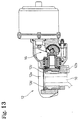
- Figs. 12 and 13 disclose a disc brake assembly in accordance with the prior art.
- This type of conventional disc brake assembly comprises two fixed-caliper service disc brakes 11 and a mechanical floating-caliper parking disc brake 12 mounted between the two fixed-caliper service disc brakes 11.
- the parking disc brake 12 and the service disc brakes 11 are peripherally distributed along a disc rotor 10 with equal intervals.
- Calipers 11a of the respective service disc brakes 11 are fixed by two installation bolts 14 on a mounting bracket 13 which is a stationary part of the vehicle.
- the parking disc brake 12 includes a carrier 12b that supports a parking brake caliper 12a that is fixed on the mounting bracket 13 by second installation bolts 15.
- the service disc brakes 11 include a pair of frictional pads (not shown in the diagram) that are adapted to be pressed against the side surfaces of the rotor 10 by a fluid pressure operation mechanism built in the service disc brakes 11, thereby causing a braking effect.
- the parking disc brake 12 includes a pair of friction pads 12c, 12d that are adapted to be pressed against the side surfaces of the rotor 10 by a mechanical operation mechanism built in the parking disc brake 12, thereby causing a brake effect.
- the parking disc brake 12 has the carrier 12b as a component.
- both the carrier 12b and the second installation bolts 15 that fix the carrier 12b on the mounting bracket 13 require higher material costs, working costs, and surface treatment costs.
- the parking disc brake 12 needs to be larger in the circumferential direction of the rotor 10 for the carrier 12b, the size of the parking disc brake 12 is increased. Since the disc brake needs to be somewhat larger, it has disadvantages with respect to the weight and the manufacturing cost as well as the fuel consumption of the vehicle.
- the present invention is intended to improve the above-mentioned aspects.
- the invention provides a smaller device with lower cost.
- a disc brake assembly comprises two hydraulic type service disc brakes that are adapted to press against a disc rotor from opposite sides to cause a braking effect, and further includes a mechanical floating-caliper type disc brake as a parking brake, wherein the mechanical floating-caliper type parking disc brake is provided between the two hydraulic type service disc brakes which are disposed spaced apart in the circumferential direction of the disc rotor with a certain distance between them and wherein component parts of the two hydraulic type service disc brakes are used as a torque-receiving part of the mechanical floating-caliper type parking disc brake.
- the hydraulic type service disc brakes are of a fixed-caliper type.
- the torque-receiving part is a caliper.
- the torque-receiving part is a carrier.
- the disc brake further includes tightening parts that attach the mechanical floating-caliper type parking disc brake on a stationary part, wherein the tightening parts also attach the hydraulic type service disc brakes on the stationary part.
- the mechanical floating-caliper type parking disc brakes include a spring chamber type operating mechanism.
- the present invention is directed toward disc brake systems, in particular for use in vehicles. Specific details of various embodiments of the invention are set forth in the following description and in Figs. 1 to 11 attached thereto in order to facilitate a thorough understanding of such embodiments. A person of ordinary skill in the art, however, will understand that the present invention may be realized in additional embodiments and that the invention may also be practiced without several of the details described in the following description.
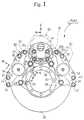
- a disc brake assembly 100 includes two hydraulic service disc brakes 30 circumferentially distributed along a rotor 20, and a mechanical parking disc brake 40 provided between the service disc brakes 30.
- the service disc brake 30 and the parking disc brake 40 are designed so that a part of one of the service disc brakes 30 may have a double function and also work as a torque-receiving part of the parking disc brake 40, and an installation bolt for the parking disc brake 40 may also serve as the installation bolt for one of the service disc brakes 30.
- the two service disc brakes 30 shown in Figs. 1 and 2 of the drawings are of the fixed-caliper hydraulic type. These service disc brakes 30 apply braking by pressing against opposite sides of the rotor 20.
- the service disc brakes 30 are offset above a horizontal line passing through the center of the rotor 20 of Fig. 1 and are placed approximately symmetrically with respect to a vertical line passing through the center of the rotor 20.
- Fig. 3 illustrates a plan view
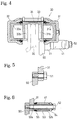
- Fig. 4 illustrates a partial cross-sectional view of the service disc brake 30.
- the service disc brake 30 includes an inner caliper 31 having an inner piston 31a therein, and an outer caliper 32 having an outer piston 32a therein, wherein the inner piston 31a and the outer piston 32a are slidably provided along the sides of the rotor 20.
- the inner and outer calipers 31 and 32 have portions that cover the periphery of the rotor 20 and are integrated by bolts 35 (see Fig. 1) along the butt joints of both calipers 31 and 32.
- An inner pad 31b and an outer pad 32b face inner and outer surfaces of the rotor 20, respectively, and are slidably supported by a pair of pins 33 disposed between the inner and outer calipers 31 and 32.
- both the inner and outer pads 31b and 32b are also slidably mounted on rails (not shown) of the calipers 31 and 32.
- a first antirattle spring 34 extends between each of the inner and outer pads 31b and 32b and the pins 33.
- the inner and outer pistons 31a and 32a are projected to press both the inner and outer pads 31b and 32b against the side surfaces of the rotor 20 by a fluid pressure created, for example, by stepping on a brake pedal.
- a first end of the inner caliper 31 opposite from the parking disc brake 40 is attached to a mounting bracket 50 (i.e. a stationary part of the vehicle), by an installation bolt 51.
- Fig. 5 illustrates a cross-sectional view of the installation bolt 51, which is similar to a conventional device.
- a second end of the inner caliper 31 situated proximate to the parking disc brake 40, and a guide bush 53 are mounted on the mounting bracket 50 by a guide bolt 52 (see Fig. 1).
- the parking disc brake 40 has a parking brake caliper 41 that slidably engages the guide bush 53, as best seen in Fig. 6.
- a screw 52a formed only on a top end of the guide bolt 52 is screwed into the mounting bracket 50, and the guide bush 53 covers a shaft 52b of the guide bolt 52.
- the parking brake caliper 41 is slidably supported along the longitudinal direction of the guide bolt 52 via the guide bush 53.
- An inner dust boot 55 extends between the parking brake caliper 41 and the inner caliper 31, and an outer dust boot 54 extends between the parking brake caliper 41 and the guide bush 53.
- the inner and outer dust boots 54 and 55 prevent any objects or particles from interfering with the sliding portion of the parking brake caliper 41 of the parking disc brake 40.
- the guide bolts 52 serve at least two functions. First, the guide bolts 52 install both adjacent portions of the parking disc brake 40 and the service disc brakes 30, and second they support the parking disc brake 40 under the floating condition, as described more fully below.
- the parking disc brake 40 is a mechanical type disc brake that is adapted to press against the rotor 20 from opposite sides of the rotor 20 and is provided on an upper part of the vertical line passing through the center of the rotor 20.
- the need for an extra torque-receiving part (such as the carrier 12b in the above-explained conventional technology) only for the parking disc brake 40 is eliminated by using the component parts of the two service disc brakes 30 as a torque-receiving part of the parking disc brake 40.
- the mechanical parking disc brake 40 comprises the parking brake caliper 41, the caliper 41 being slidably supported on the guide bush 53 in the axial direction of the rotor 20, the guide bush 53 covering the guide bolt 52.
- the parking disc brake 40 also includes inner and outer parking brake pads 42a and 42b provided on inner and outer rails 31c and 32c of the inner and outer calipers 31 and 32, respectively, of the service disc brakes 30 explained above, and a mechanical operating mechanism 200 adapted to directly press the inner parking brake pad 42a.
- a sleeve 43 is forcefully fitted in a cylinder 41a of the parking brake caliper 41.
- An adjustment nut 44 is slidably inserted in the sleeve 43, and a tappet 45 is screwed into the adjustment nut 44 to press against the inner parking brake pad 42a.
- a return spring 66 is compressed between the parking brake caliper 41 and the adjustment nut 44 and applies a spring force to continuously abut a washer 46 installed with the adjustment nut 44 against a roller 65 engaged with a recess of an eccentric cam 62a of an operating lever 62.
- First adjustment teeth 44a provided on the adjustment nut 44 engage second adjustment teeth 47a provided on a circumferential surface of a large diameter portion of an adjustment shaft 47 provided parallel to the adjustment nut 44.
- the adjustment nut 44 is rotated by operating the adjustment shaft 47 externally from the parking brake caliper 41 to manually adjust the amount of the exposed post-screwed portion of the tappet 45 relative to the adjustment nut 44.
- a spring chamber assembly 60 is fastened to the parking brake caliper 41 and comprises a built-in spring (not shown in the diagram) and a push rod 61 adapted to exert a stroke by the spring force of the built-in spring, wherein the pressing force of the push rod 61 is transmitted as the pressure force of the tappet 45 via the operating lever 62 etc..
- the operating lever 62 comprises the eccentric cam 62a, a pair of linkages 62b integrally extendable from both sides in the axial direction of the eccentric cam 62a, and a receiving part 62c abutting against the push rod 61, wherein the receiving part 62c is a pin bridging between the facing linkages 62b, both ends of which are fixed to the facing linkages 62b.
- a second antirattle spring 48 is provided between the parking brake caliper 41 and the inner and outer parking brake pads 42a and 42b to prevent any rattling of the parking brake pads 42a and 42b.
- a needle bearing 63 and a sheet bearing 64 are engaged with the operating lever 62 to provide a smooth rotation of the operating lever 62.
- a fixed anchor 67 supports the needle bearing 63.
- a plate 68 is inserted between a flange of the adjustment nut 44 and a return spring 66 and has a low friction layer that does not transmit any torsion force from the return spring 66 to the adjustment nut 44.
- a dust boot 69 extends between the tappet 45 and the sleeve 43.
- the end surfaces, when viewed in the circumferential direction of the rotor 20, of both the inner and outer parking pads 42a and 42b of the parking disc brake 40 are slidably attached in the axial direction of the rotor 20 to the adjacent end surfaces of the service disc brakes 30, namely the inner and outer rails 31c and 32c formed at the inner caliper 31 and the outer caliper 32.
- the braking torque of the parking disc brake 40 is supported by the services disc brakes 30, in other words the component parts of the service disc brakes 30 are used as the torquereceiving parts of the parking disc brake 40.
- the parking brake is operated to eject air in the spring chamber assembly 60.
- the push rod 61 is projected by the spring force of a built-in spring (not shown) and the receiving part 62c of the operating lever 62 is pressed in the direction of the rotor 20.
- the eccentric cam 62a integrated with each linkage 62b rotates counter-clockwise in Fig. 7.
- the eccentric cam 62a presses the washer 46 in the direction of the rotor 20 via the roller 65.
- the pressure force is transmitted to the tappet 45 via the adjustment nut 44, and the tappet 45 presses the inner parking brake pad 42a into contact with the rotor 20.
- the parking brake caliper 41 moves backward in the opposite direction of the tappet 45, causing the reaction part 41b of the parking brake caliper 41 to press the outer parking brake pad 42b in the direction of the rotor 20.
- the inner and outer parking brake pads 42a and 42b press against the rotor 20 in opposite directions to effectuate braking.
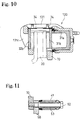
- Figs. 8 to 11 illustrate another embodiment of a disc brake assembly 300 having two hydraulic, floating-caliper type service disc brakes 130.
- components which are similar or identical to the components of the above-described embodiments are designated with the same numbers, and the explanation of such components is not repeated.
- Each floating-caliper type service disc brake 130 comprises a carrier 70 fixed to the mounting bracket 50, the installation bolts 51, and the guide bolts 52.
- a floating caliper 131 having a reaction part 131c is slidably supported by first and second guiding means 71 and 72, respectively, and is thereby fixed to the carrier 70.
- Inner and outer pads 31b and 32b are slidably provided on a rail 70b (see Fig. 8) of the carrier 70, the rail 70b extending in the axial direction of the rotor 20.
- the guide bolts 52 are shared to fix both the guide bush 53, see Fig. 11, on which the parking brake caliper 41 slides, and the carriers 70 comprise the floating-caliper type service disc brakes 130. Furthermore, an end surface of the inner and outer parking brake pads 42a and 42b (the inner parking brake pad 42a is shown in Fig. 8) of the parking disc brake 40 is provided oh the respective rails 70a of the carriers 70, and the braking torque of the parking disc brake 40 is received by the carriers 70.
- the braking effect is caused by the inner pad 31b being pressed against the rotor 20 by the piston 31a built in the inner side of the floating caliper 131, and the outer pad 32b being pressed against the rotor 20 by the reaction part 131c of the floating caliper 131.
- the input portion of the floating-caliper type parking disc brake 40 is not limited to the spring chamber type.
- a cable may be used to pull the receiving part 62c of the operating lever 62.
- the mechanical operating portion of the parking disc brake 40 is not limited to the type having the eccentric cam 62a.
- a leverage type, a ball and ramp type, a wedge type etc. may be used as a mechanical operating portion.
- the system only requires a mechanical floating-caliper type disc brake.
- the guide bushes 53, on which the parking brake caliper 41 of the parking disc brake 40 slides, and the service disc brakes 30 are both fixed on the mounting brackets 50 by the common guide bolts 52.
- the installation bolts 51 are not shared. In this way, the braking torque of the parking disc brake 40 is received by the component parts of the service disc brakes 30.
- the input part of the floating-caliper type service disc brakes 130 is not limited to the type in which the hydraulic pressure is directly supplied.
- the input source may be a hydraulic pressure, but the floating-type service disc brake 130 may be of the type in which a hydraulic pressure is indirectly supplied such as, for example, via a mechanical mechanism, e.g. an air-chamber type disc brake.
- this invention has several advantages over the prior art.
- the component parts of the hydraulic type service disc brake are provided in a line to use the torque-receiving parts of the mechanical type parking disc brake.
- the stationary part i.e. the mounting bracket
- the stationary part i.e. the mounting bracket
- a carrier of the parking disc brake is not necessary which also reduces weight and enables the device to be designed smaller.
- the weight is lower, the fuel consumption rate of the vehicle is improved.
- Another feature of the invention is that the installation fastener part of the guide bush where the caliper of the parking disc brake slides, and the installation fastener part for the service disc brake, may be shared. This advantageously reduces the number of component parts, and thus the cost, weight and assembly process. Another advantage is that either the fixed-caliper type or the floating-caliper type may be used for the service disc brake, which provides more flexibility.
Landscapes
- Engineering & Computer Science (AREA)
- General Engineering & Computer Science (AREA)
- Mechanical Engineering (AREA)
- Transportation (AREA)
- Braking Arrangements (AREA)
Applications Claiming Priority (2)
| Application Number | Priority Date | Filing Date | Title |
|---|---|---|---|
| JP4458198 | 1998-02-10 | ||
| JP04458198A JP3901329B2 (ja) | 1998-02-10 | 1998-02-10 | ディスクブレーキ装置 |
Publications (2)
| Publication Number | Publication Date |
|---|---|
| EP0936372A1 true EP0936372A1 (fr) | 1999-08-18 |
| EP0936372B1 EP0936372B1 (fr) | 2002-12-11 |
Family
ID=12695468
Family Applications (1)
| Application Number | Title | Priority Date | Filing Date |
|---|---|---|---|
| EP99102419A Expired - Lifetime EP0936372B1 (fr) | 1998-02-10 | 1999-02-08 | Ensemble de frein à disque avec des éléments récepteurs de couple partagés |
Country Status (4)
| Country | Link |
|---|---|
| US (1) | US6488132B2 (fr) |
| EP (1) | EP0936372B1 (fr) |
| JP (1) | JP3901329B2 (fr) |
| DE (1) | DE69904381D1 (fr) |
Cited By (10)
| Publication number | Priority date | Publication date | Assignee | Title |
|---|---|---|---|---|
| EP1186524A3 (fr) * | 2000-09-08 | 2002-12-04 | Honda Giken Kogyo Kabushiki Kaisha | Dispositif de freinage |
| EP1126190A3 (fr) * | 2000-02-14 | 2003-10-22 | Bayerische Motoren Werke Aktiengesellschaft | Frein à disque à garniture partielle pour un véhicule automobile |
| EP1564429A1 (fr) * | 2004-02-12 | 2005-08-17 | Deere & Company | Plaque de support et procédé pour fixation d'un étrier de frein à disque. |
| WO2006039794A1 (fr) * | 2004-10-12 | 2006-04-20 | 2040422 Ontario Inc. . | Systeme de frein a disque |
| ITBS20090060A1 (it) * | 2009-03-25 | 2010-09-26 | Mario Gaia | Dispositivo per frenare e/o ruotare in continuo le ruote di veicoli ed aerei |
| WO2016015274A1 (fr) * | 2014-07-31 | 2016-02-04 | 伍洪少 | Frein au pied et système de double frein |
| EP2878504A4 (fr) * | 2012-07-24 | 2016-08-17 | Haisheng Qiang | Procédé de freinage bidirectionnel pour frein à disque et mécanisme de freinage et applications associés |
| CN109695642A (zh) * | 2017-10-20 | 2019-04-30 | 曙制动器工业株式会社 | 每个转子的多卡钳制动组件 |
| CN112810582A (zh) * | 2021-02-02 | 2021-05-18 | 广州市华劲机械制造有限公司 | 盘刹车桥 |
| EP3835081A1 (fr) * | 2019-12-10 | 2021-06-16 | ZF CV Systems Europe BV | Essieu de véhicule utilitaire doté d'un frein à disque |
Families Citing this family (32)
| Publication number | Priority date | Publication date | Assignee | Title |
|---|---|---|---|---|
| US7025181B2 (en) * | 2002-05-09 | 2006-04-11 | Affeldt Wayne W | Automotive brake system |
| JP2004217193A (ja) * | 2002-11-20 | 2004-08-05 | Kobelco Contstruction Machinery Ltd | 軌道用作業機 |
| US6811004B1 (en) * | 2003-05-09 | 2004-11-02 | Arvinmeritor Technology, Llc | Vehicle brake assembly having a bearing block closure and method of assembly therefor |
| US20060018206A1 (en) * | 2004-07-26 | 2006-01-26 | Miho Akitomo | Contents delivering method |
| DE102004058433A1 (de) * | 2004-12-03 | 2006-06-22 | Knorr-Bremse Systeme für Nutzfahrzeuge GmbH | Scheibenbremse für ein Fahrzeug |
| DE102005003223B4 (de) * | 2005-01-24 | 2007-02-01 | Haldex Brake Products Ab | Scheibenbremse mit Nachstelleinrichtung |
| JP4977141B2 (ja) * | 2005-10-05 | 2012-07-18 | フレニ・ブレンボ エス・ピー・エー | フットブレーキとパーキングブレーキを組み合せた車両用ディスク式制動装置 |
| US7395904B2 (en) * | 2005-12-20 | 2008-07-08 | Robert Basoh Gmbh | Disc brake |
| JP4945604B2 (ja) * | 2009-07-10 | 2012-06-06 | 本田技研工業株式会社 | 自動二輪車の制動装置 |
| AU2010100626A4 (en) * | 2009-12-08 | 2010-08-19 | Advanced Braking Pty Ltd | Disc Brake System |
| CN101947949A (zh) * | 2010-09-14 | 2011-01-19 | 陈明洁 | 一种双卡钳汽车制动器 |
| US20120247885A1 (en) * | 2011-03-31 | 2012-10-04 | Bendix Spicer Foundation Brake Llc | Adaptive Torque Plates |
| WO2013001330A1 (fr) * | 2011-06-30 | 2013-01-03 | Renault Trucks | Étrier de frein pour un frein de base d'un véhicule automobile, actionneur de frein et frein de base comprenant ledit étrier de frein et ledit actionneur |
| KR101204398B1 (ko) | 2011-12-19 | 2012-11-26 | 한국기계연구원 | 기계식 브레이크 릴리스 장치 |
| DE102011056575A1 (de) * | 2011-12-19 | 2013-06-20 | Dr. Ing. H.C. F. Porsche Aktiengesellschaft | Kraftfahrzeugbremssystem |
| US9777782B2 (en) * | 2013-06-19 | 2017-10-03 | Kelsey-Hayes Company | Shared anchor bracket for a disc brake assembly having separate service and parking brake assemblies |
| JP6208065B2 (ja) * | 2014-03-31 | 2017-10-04 | 曙ブレーキ工業株式会社 | 対向ピストン型ディスクブレーキ装置 |
| EP3051170B1 (fr) * | 2015-01-28 | 2019-10-23 | Meritor Heavy Vehicle Braking Systems (UK) Limited | Frein à disque |
| DE102015002892A1 (de) * | 2015-03-05 | 2016-09-08 | Wabco Europe Bvba | Achse eines Landfahrzeugs, Landfahrzeug mit einer solchen Achse sowie Scheibenbremse und Bremsenträger eines solchen Landfahrzeugs |
| USD771540S1 (en) * | 2015-06-15 | 2016-11-15 | Saf-Holland, Inc. | Brake spider |
| USD801895S1 (en) * | 2015-09-22 | 2017-11-07 | Saf-Holland, Inc. | Brake torque plate |
| TWM530777U (zh) * | 2016-07-26 | 2016-10-21 | Jieh Jia Entpr Co Ltd | 電子式煞車卡鉗 |
| US10302160B2 (en) | 2017-04-26 | 2019-05-28 | Akebono Brake Industry Co., Ltd. | Brake caliper assembly |
| IT201800020251A1 (it) | 2018-12-20 | 2020-06-20 | Freni Brembo Spa | Corpo pinza e pinza freno con detto corpo |
| US11015667B2 (en) | 2019-05-28 | 2021-05-25 | Michael Pagano | Brake mounting bracket |
| JP7136027B2 (ja) * | 2019-07-17 | 2022-09-13 | トヨタ自動車株式会社 | ディスクブレーキ |
| CN111059179A (zh) * | 2019-12-02 | 2020-04-24 | 太原科技大学 | 一种变载荷型高效散热式制动器 |
| KR102593295B1 (ko) * | 2020-12-23 | 2023-10-24 | 스톨츠 주식회사 | 디스크 결합 유닛 |
| EP4219976A1 (fr) * | 2022-01-28 | 2023-08-02 | KNORR-BREMSE Systeme für Nutzfahrzeuge GmbH | Étrier de frein de stationnement avec configuration de levier inversé |
| IT202200010166A1 (it) * | 2022-05-17 | 2023-11-17 | Fca Italy Spa | "Autoveicolo, in particolare autoveicolo elettrico, con trasmissione automatica bloccabile in condizione di parking tramite pinze freno elettro-attuate associate alle ruote motrici" |
| KR20240171415A (ko) * | 2023-05-30 | 2024-12-09 | 현대모비스 주식회사 | 브레이크 장치 및 이를 구비하는 차량 |
| CN119289004B (zh) * | 2024-12-10 | 2025-03-21 | 镇江合力汽车紧固件有限公司 | 一种双卡钳汽车制动器、对称组装设备及组装方法 |
Citations (5)
| Publication number | Priority date | Publication date | Assignee | Title |
|---|---|---|---|---|
| US3321049A (en) * | 1965-05-12 | 1967-05-23 | Kelsey Hayes Co | Mechanical floating head brake |
| GB1490795A (en) * | 1974-02-18 | 1977-11-02 | Perrot Bremse Gmbh Deutsche | Disc brake |
| DE2657015A1 (de) * | 1976-12-16 | 1978-09-07 | Volkswagenwerk Ag | Aufhaengung eines kraftfahrzeugrades |
| DE2718003A1 (de) * | 1977-04-22 | 1978-10-26 | Knorr Bremse Gmbh | Scheibenbremse fuer fahrzeuge, insbesondere strassenfahrzeuge |
| GB2012012A (en) * | 1978-01-04 | 1979-07-18 | Perrot Bremse Gmbh Deutsche | Disc brake, especially for motor vehicles |
Family Cites Families (9)
| Publication number | Priority date | Publication date | Assignee | Title |
|---|---|---|---|---|
| US3318421A (en) | 1964-10-26 | 1967-05-09 | Gen Motors Corp | Brake adjusting system |
| US3342291A (en) | 1965-06-28 | 1967-09-19 | Gen Motors Corp | Manually actuated spot-type disc brake and adjusting means |
| US3613515A (en) * | 1969-03-10 | 1971-10-19 | Certain Teed Prod Corp | Brake actuator |
| US3651896A (en) | 1970-06-19 | 1972-03-28 | Dayton Steel Foundry Co | Hydraulic disk brake with mechanical actuator |
| US3837437A (en) | 1973-01-22 | 1974-09-24 | Airheart Prod | Ratchet actuated brake wear compensation |
| JPS5817890B2 (ja) | 1976-11-20 | 1983-04-09 | トキコ株式会社 | 機械式デイスクブレ−キ |
| GB9001565D0 (en) | 1990-01-23 | 1990-03-21 | Gen Motors France | Disc brake |
| US5607033A (en) | 1995-11-02 | 1997-03-04 | Mark + Technologies, Inc. | Disc brake caliper having a linear slack adjuster assembly |
| US5845747A (en) | 1995-11-13 | 1998-12-08 | Dayton Walther Corporation | Piston with extended outer cover for use in disc brake assembly |
-
1998
- 1998-02-10 JP JP04458198A patent/JP3901329B2/ja not_active Expired - Fee Related
-
1999
- 1999-02-08 DE DE69904381T patent/DE69904381D1/de not_active Expired - Lifetime
- 1999-02-08 EP EP99102419A patent/EP0936372B1/fr not_active Expired - Lifetime
-
2001
- 2001-07-30 US US09/919,342 patent/US6488132B2/en not_active Expired - Fee Related
Patent Citations (5)
| Publication number | Priority date | Publication date | Assignee | Title |
|---|---|---|---|---|
| US3321049A (en) * | 1965-05-12 | 1967-05-23 | Kelsey Hayes Co | Mechanical floating head brake |
| GB1490795A (en) * | 1974-02-18 | 1977-11-02 | Perrot Bremse Gmbh Deutsche | Disc brake |
| DE2657015A1 (de) * | 1976-12-16 | 1978-09-07 | Volkswagenwerk Ag | Aufhaengung eines kraftfahrzeugrades |
| DE2718003A1 (de) * | 1977-04-22 | 1978-10-26 | Knorr Bremse Gmbh | Scheibenbremse fuer fahrzeuge, insbesondere strassenfahrzeuge |
| GB2012012A (en) * | 1978-01-04 | 1979-07-18 | Perrot Bremse Gmbh Deutsche | Disc brake, especially for motor vehicles |
Cited By (11)
| Publication number | Priority date | Publication date | Assignee | Title |
|---|---|---|---|---|
| EP1126190A3 (fr) * | 2000-02-14 | 2003-10-22 | Bayerische Motoren Werke Aktiengesellschaft | Frein à disque à garniture partielle pour un véhicule automobile |
| EP1186524A3 (fr) * | 2000-09-08 | 2002-12-04 | Honda Giken Kogyo Kabushiki Kaisha | Dispositif de freinage |
| EP1564429A1 (fr) * | 2004-02-12 | 2005-08-17 | Deere & Company | Plaque de support et procédé pour fixation d'un étrier de frein à disque. |
| WO2006039794A1 (fr) * | 2004-10-12 | 2006-04-20 | 2040422 Ontario Inc. . | Systeme de frein a disque |
| ITBS20090060A1 (it) * | 2009-03-25 | 2010-09-26 | Mario Gaia | Dispositivo per frenare e/o ruotare in continuo le ruote di veicoli ed aerei |
| WO2010109504A1 (fr) * | 2009-03-25 | 2010-09-30 | Mario Gaia | Dispositif de freinage continu et/ou de rotation des roues de véhicules et d'aéronefs |
| EP2878504A4 (fr) * | 2012-07-24 | 2016-08-17 | Haisheng Qiang | Procédé de freinage bidirectionnel pour frein à disque et mécanisme de freinage et applications associés |
| WO2016015274A1 (fr) * | 2014-07-31 | 2016-02-04 | 伍洪少 | Frein au pied et système de double frein |
| CN109695642A (zh) * | 2017-10-20 | 2019-04-30 | 曙制动器工业株式会社 | 每个转子的多卡钳制动组件 |
| EP3835081A1 (fr) * | 2019-12-10 | 2021-06-16 | ZF CV Systems Europe BV | Essieu de véhicule utilitaire doté d'un frein à disque |
| CN112810582A (zh) * | 2021-02-02 | 2021-05-18 | 广州市华劲机械制造有限公司 | 盘刹车桥 |
Also Published As
| Publication number | Publication date |
|---|---|
| US6488132B2 (en) | 2002-12-03 |
| JPH11230201A (ja) | 1999-08-27 |
| JP3901329B2 (ja) | 2007-04-04 |
| US20020007989A1 (en) | 2002-01-24 |
| DE69904381D1 (de) | 2003-01-23 |
| EP0936372B1 (fr) | 2002-12-11 |
Similar Documents
| Publication | Publication Date | Title |
|---|---|---|
| EP0936372A1 (fr) | Ensemble de frein à disque avec des éléments récepteurs de couple partagés | |
| US7950502B2 (en) | Electromechanically actuated disc brake with guide plate | |
| US8739945B2 (en) | Disc brake adjusting device having an output side coupling ring with a defined working rotational angle | |
| US6302243B1 (en) | Stiffening bracket for brake calipers | |
| US8944221B2 (en) | Disk brake for a commercial vehicle | |
| US6119818A (en) | Disk brake | |
| US7086506B2 (en) | Pad retraction spring for a brake shoe assembly and a disc brake assembly | |
| EP0877176A3 (fr) | Conception d'un frein à disque anti-cliquetis | |
| JPH05196067A (ja) | 高出力車両用フローティングフレームスポット型ディスクブレーキ | |
| US4375250A (en) | Spot-type disc brake | |
| US8167096B2 (en) | Electromechanically or pneumatically actuable disc brake, in particular for a commercial vehicle | |
| US8851241B2 (en) | Hydraulic disc brake having a parking brake mechanism | |
| US4865161A (en) | Sliding saddle disc brake | |
| US6068091A (en) | Externally mounted bracket system for disc brakes | |
| EP2174036A1 (fr) | Dispositif de stationnement d'étrier de frein | |
| US20240392850A1 (en) | Disc Brake for a Utility Vehicle | |
| US8616347B2 (en) | Pneumatically actuable disc brake | |
| EP0733172A1 (fr) | Tambour de frein avec levier de frein de stationnement actionne par came | |
| WO1998006608A2 (fr) | Mecanisme d'actionnement electromecanique pour ensemble de freins a disques | |
| JPS5817133Y2 (ja) | 自動車用デイスクブレ−キのパツドの振動防止装置 | |
| KR200267458Y1 (ko) | 차량용 브레이크장치의 드럼브레이크 | |
| EP4311953B1 (fr) | Dispositif de freinage de stationnement pour un véhicule | |
| JPS6140968Y2 (fr) | ||
| JP2002235779A (ja) | パーキング機構付ディスクブレーキ | |
| GB2076486A (en) | Friction pads in disc brakes |
Legal Events
| Date | Code | Title | Description |
|---|---|---|---|
| PUAI | Public reference made under article 153(3) epc to a published international application that has entered the european phase |
Free format text: ORIGINAL CODE: 0009012 |
|
| AK | Designated contracting states |
Kind code of ref document: A1 Designated state(s): DE FR GB |
|
| AX | Request for extension of the european patent |
Free format text: AL;LT;LV;MK;RO;SI |
|
| 17P | Request for examination filed |
Effective date: 19991111 |
|
| 17Q | First examination report despatched |
Effective date: 20000221 |
|
| AKX | Designation fees paid |
Free format text: DE FR GB |
|
| GRAG | Despatch of communication of intention to grant |
Free format text: ORIGINAL CODE: EPIDOS AGRA |
|
| GRAG | Despatch of communication of intention to grant |
Free format text: ORIGINAL CODE: EPIDOS AGRA |
|
| GRAH | Despatch of communication of intention to grant a patent |
Free format text: ORIGINAL CODE: EPIDOS IGRA |
|
| GRAH | Despatch of communication of intention to grant a patent |
Free format text: ORIGINAL CODE: EPIDOS IGRA |
|
| GRAA | (expected) grant |
Free format text: ORIGINAL CODE: 0009210 |
|
| AK | Designated contracting states |
Kind code of ref document: B1 Designated state(s): DE FR GB |
|
| PG25 | Lapsed in a contracting state [announced via postgrant information from national office to epo] |
Ref country code: FR Free format text: LAPSE BECAUSE OF NON-PAYMENT OF DUE FEES Effective date: 20021211 |
|
| REG | Reference to a national code |
Ref country code: GB Ref legal event code: FG4D |
|
| REF | Corresponds to: |
Ref document number: 69904381 Country of ref document: DE Date of ref document: 20030123 |
|
| PG25 | Lapsed in a contracting state [announced via postgrant information from national office to epo] |
Ref country code: GB Free format text: LAPSE BECAUSE OF NON-PAYMENT OF DUE FEES Effective date: 20030311 |
|
| PG25 | Lapsed in a contracting state [announced via postgrant information from national office to epo] |
Ref country code: DE Free format text: LAPSE BECAUSE OF FAILURE TO SUBMIT A TRANSLATION OF THE DESCRIPTION OR TO PAY THE FEE WITHIN THE PRESCRIBED TIME-LIMIT Effective date: 20030312 |
|
| PLBE | No opposition filed within time limit |
Free format text: ORIGINAL CODE: 0009261 |
|
| STAA | Information on the status of an ep patent application or granted ep patent |
Free format text: STATUS: NO OPPOSITION FILED WITHIN TIME LIMIT |
|
| GBPC | Gb: european patent ceased through non-payment of renewal fee |
Effective date: 20030311 |
|
| EN | Fr: translation not filed | ||
| 26N | No opposition filed |
Effective date: 20030912 |