EP0936379A2 - Planetengetriebe - Google Patents
Planetengetriebe Download PDFInfo
- Publication number
- EP0936379A2 EP0936379A2 EP99102519A EP99102519A EP0936379A2 EP 0936379 A2 EP0936379 A2 EP 0936379A2 EP 99102519 A EP99102519 A EP 99102519A EP 99102519 A EP99102519 A EP 99102519A EP 0936379 A2 EP0936379 A2 EP 0936379A2
- Authority
- EP
- European Patent Office
- Prior art keywords
- gear
- planetary gear
- ring gear
- output
- drive
- Prior art date
- Legal status (The legal status is an assumption and is not a legal conclusion. Google has not performed a legal analysis and makes no representation as to the accuracy of the status listed.)
- Withdrawn
Links
Images


Classifications
-
- F—MECHANICAL ENGINEERING; LIGHTING; HEATING; WEAPONS; BLASTING
- F16—ENGINEERING ELEMENTS AND UNITS; GENERAL MEASURES FOR PRODUCING AND MAINTAINING EFFECTIVE FUNCTIONING OF MACHINES OR INSTALLATIONS; THERMAL INSULATION IN GENERAL
- F16H—GEARING
- F16H1/00—Toothed gearings for conveying rotary motion
- F16H1/28—Toothed gearings for conveying rotary motion with gears having orbital motion
- F16H1/2809—Toothed gearings for conveying rotary motion with gears having orbital motion with means for equalising the distribution of load on the planet gears
- F16H1/2836—Toothed gearings for conveying rotary motion with gears having orbital motion with means for equalising the distribution of load on the planet gears by allowing limited movement of the planet gears relative to the planet carrier or by using free floating planet gears
-
- F—MECHANICAL ENGINEERING; LIGHTING; HEATING; WEAPONS; BLASTING
- F16—ENGINEERING ELEMENTS AND UNITS; GENERAL MEASURES FOR PRODUCING AND MAINTAINING EFFECTIVE FUNCTIONING OF MACHINES OR INSTALLATIONS; THERMAL INSULATION IN GENERAL
- F16H—GEARING
- F16H1/00—Toothed gearings for conveying rotary motion
- F16H1/28—Toothed gearings for conveying rotary motion with gears having orbital motion
-
- H—ELECTRICITY
- H02—GENERATION; CONVERSION OR DISTRIBUTION OF ELECTRIC POWER
- H02K—DYNAMO-ELECTRIC MACHINES
- H02K7/00—Arrangements for handling mechanical energy structurally associated with dynamo-electric machines, e.g. structural association with mechanical driving motors or auxiliary dynamo-electric machines
- H02K7/10—Structural association with clutches, brakes, gears, pulleys or mechanical starters
- H02K7/116—Structural association with clutches, brakes, gears, pulleys or mechanical starters with gears
-
- F—MECHANICAL ENGINEERING; LIGHTING; HEATING; WEAPONS; BLASTING
- F16—ENGINEERING ELEMENTS AND UNITS; GENERAL MEASURES FOR PRODUCING AND MAINTAINING EFFECTIVE FUNCTIONING OF MACHINES OR INSTALLATIONS; THERMAL INSULATION IN GENERAL
- F16H—GEARING
- F16H1/00—Toothed gearings for conveying rotary motion
- F16H1/28—Toothed gearings for conveying rotary motion with gears having orbital motion
- F16H2001/2881—Toothed gearings for conveying rotary motion with gears having orbital motion comprising two axially spaced central gears, i.e. ring or sun gear, engaged by at least one common orbital gear wherein one of the central gears is forming the output
-
- F—MECHANICAL ENGINEERING; LIGHTING; HEATING; WEAPONS; BLASTING
- F16—ENGINEERING ELEMENTS AND UNITS; GENERAL MEASURES FOR PRODUCING AND MAINTAINING EFFECTIVE FUNCTIONING OF MACHINES OR INSTALLATIONS; THERMAL INSULATION IN GENERAL
- F16H—GEARING
- F16H57/00—General details of gearing
- F16H57/08—General details of gearing of gearings with members having orbital motion
- F16H57/10—Braking arrangements
Definitions
- the invention relates to a planetary gear with a fixed gear housing, which is closed by a lid with a rotating drivable Inner wheel, whose axis of rotation forms the central axis of the transmission, with a fixed drive-side and with internal toothing ring gear and a rotatable ring gear on the output side with internal teeth and at least one in engagement with the ring gears and the sun gear Planetary gear and with one with its longitudinal axis in the central axis of the planetary gear support wheel, which with the planet gear or with engages several planet gears.
- the planetary gear in question is also referred to as a planetary gear and is known in many versions.
- Gear transmissions are particularly preferred, where there is at least one planet gear other than its own axis, the so-called Orbital axis, also rotates around the central axis.
- the area of application is diverse, for example as drives for control devices, Adjusting drives in mechanical engineering and the like.
- the invention has for its object a planetary gear closer to the beginning type described so that the adherence to the compact design Friction losses are as low as possible, so that the efficiency is increased and that the play of the engaged wheels is kept as low as possible and that the speed ratio between the input and the output side of the planetary gear can be increased.
- the output-side ring gear the side facing the sun gear of the wheel assembly into the bore of the Support wheel engaging pin is assigned, on which the support wheel rotates freely or is rotatably mounted.
- the in the bore of the jockey wheel engaging pin can be formed on the output side ring gear be integrally formed with this or be part of an output pin, the is rotatably mounted in the output side ring gear.
- the planetary gear is through this pin stabilized at a critical point.
- the output-side ring gear is additionally fixed if it is Pin contacts the free end of the motor pin.
- the engine pin is included to be regarded as a stationary component.
- the pin designed spherically on the end facing the motor pin. This will make one smallest possible contact area created.
- at least the pin on the side facing the motor shaft has a recess in which a ball is mounted.
- the output side ring gear can be made of a metal or a plastic. Because the engine pin Always made of steel, the ball should be made of a suitable material consist. A plastic or a metal could also be used. The material the ball is therefore made of the material of the motor pin and the output side Ring gear dependent. Especially if the ring gear is made of a plastic is made, it is advantageous if the pin is designed as a hollow pin, because then material accumulation is avoided.
- each planet gear at least on the side facing the output flange projecting guide pin, but preferably on both ends projecting guide pin, which or in the ring grooves of the output flange and the bottom of the housing are guided.
- the guide pins can be used Spraying process with be injected.
- the planet gears are made of metal, could the guide pin advantageously through a hole in the Planetary fixed bolts are formed.
- the pilot pins are Particularly advantageous with such planetary gears, the torques in the middle and upper area transferred.
- the planet gears are through the guide pin or through the guide pin additionally managed and stabilized.
- an output pin is rotatably inserted into the bore of the loose support wheel is, which is preferably rotatably mounted in the output-side ring gear and its free end opposite the free end of a hub of the driven end Ring gear protrudes. Since the output pin with the least possible play in the output side Ring gear is mounted, the jockey wheel and thus the in Interacting planet gears guided exactly.
- the wheels forming the closed chain are in a first version designed as spur gears.
- the wheels could be used to further reduce noise be helically toothed, the first stage of the transmission through the input side Ring gear and the second stage of the transmission determined by the output side ring gear is.
- the wheels of the wheels belonging to the second stage could then be the same or be toothed in opposite directions to the wheels of the first stage, so that the opposing teeth would cancel the axial forces.
- the wheels of the self-contained chain of wheels are designed as friction wheels. This execution is simple and advantageous, especially when relatively small torques are transmitted. Furthermore Manufacturing is significantly simplified since the wheels are injection molded, for example can be produced.
- the planetary gear is normally a non-self-locking gear.
- the adjustment device for example, the upward movement and the downward movement could be exclusive Execute with the drive motor in operation. In such cases it is sufficient if the planetary gear is not self-locking.
- the adjustment unit to be adjusted within the positioning area should remain in many positions, even if they is charged.
- the transmission is reversible in the direction of rotation Gearbox is designed, but in the opposite direction of rotation is self-locking, d. H. if the output pin from the connected adjustment unit is driven.
- the planetary gear and / or the planetary gear driving drive motor is equipped with one brake each preferably a control device controlling the braking force is assigned.
- the planetary gear could be designed so that within the self-contained wheel arrangement when reversing the direction of rotation, d. H. if the output member has a driving effect, a blockage occurs.
- Another The wheel arrangement is stabilized when the output-side ring gear a projecting and on the side facing the drive-side ring gear has a hollow approach, on which a roller bearing is placed. It could each planet gear has a recess open to the drive-side ring gear, in which a ball loaded by a compression spring partially engages.
- a brake element for example a wrap spring brake element assigned.
- This braking element can be directly on the outer circumference of the output side ring gear. Unless, however, this ring gear in a bearing sleeve is stored, it is provided that it with a cylindrical brake member is rotatably connected, on the peripheral surface engages the braking element.
- a wrap spring brake element it is advantageous if the wires are one have a square, preferably square, cross section. Then it will the largest possible friction surface between the wrap spring brake element and the cylindrical brake link reached. In addition, this braking element may then act also as a slip clutch.
- the drive-side ring gear is fixed to the Housing of the planetary gear connected or the toothing is in one piece with the housing.
- drive-side ring gear is rotatably mounted in the housing, but by means of a holding member is set in normal operation. This holding member could for example consist of one or more brake shoes, so that to disengage the planetary gear the brake shoes are released. Then there is the braking force can be regulated, the lowering takes place on a connected adjustment unit with a variable speed to be determined from case to case.
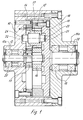
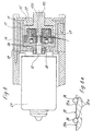
- the seamless planetary gear shown in FIG. 1 has a further explained self-contained wheel arrangement arranged within a housing 10 is.
- the housing 10 is closed by means of a screwed cover 11.
- On the housing 10 is an outwardly projecting hub 10a and on the cover an outwardly projecting hub 11a is formed.
- the hubs 10a and 11a lie aligned with each other.
- a drive pin 12 mounted by means of roller bearings 25.
- This drive pin 12 can Pin of an electric drive motor, not shown, or the drive pin 12 can be connected to the motor shaft by means of a coupling.
- a sun gear 13 designed as a spur gear is attached in a rotationally fixed manner.
- a first ring gear 14 is inserted into the housing 10, which is pinned to the gear housing 10 so that this ring gear 14 fixed stands.
- the outside diameter of the ring gear 14 coincides with the inside diameter of the housing 10 match.
- the nominal diameter is a little bit smaller than the inside diameter of the housing 10.
- Execution could be the ring gear 14 in a corresponding manufacturing process be integral with the side walls of the housing 10.
- a second ring gear 15 is arranged directly next to the first ring gear 14 is also provided with an internal toothing, the nominal diameter is slightly less than that of the ring gear 24.
- a support wheel 16 designed as a spur gear in the exemplary embodiment shown arranged.
- the width of the sun gear 13 coincides with the width of the first ring gear 14 match.
- the width of the second ring gear 15 matches the width the support wheel 16 match.
- the nominal diameter of the ring gear 15 is a little bit larger than that of the sun gear 13.
- the internal toothing of the first ring gear 14 and the second ring gear 15 are depending on the design of the planetary gear engages with one or more planet gears 17, which also with the Sun gear 13 and the support wheel 16 are engaged.
- each planet gear 17 is different Stepped diameters.
- the second ring gear 15 is of the same diameter Output flange 18 firmly connected by screws.
- On the output flange 18 is an output pin which is mounted in the hub 11a of the cover 11 by means of roller bearings 19 20 scheduled.
- the diameter is the central bore of the support wheel 16 is significantly larger than the outer diameter of the drive pin 12.
- the support wheel 16 requires at least two planet gears 17, which by one Angles of 180 ° are offset from one another.
- the Drive pin 12 extends only through the bore of the sun gear 13.
- the planetary gear should only be equipped with a planet gear 17 , it is necessary that the support wheel 16 loosely on the drive pin 12th is placed because it performs a relative movement in the operation of the planetary gear and the drive pin 12 rotates.
- the embodiment shown has the advantage that that assigned to the output flange 18 End of the drive pin 12 are still stored in the output flange 18 can.
- the support wheel 16 is designed as a spur gear.
- Friction wheel can be designed to support the planet gear 17 or the planet gears 17.
- the sun gear 13 drives the planet gear 17 or the planet gears 17 on. Since they are in the internal toothing of the first, fixed ring gear Roll 14 and the internal teeth of the rotatable ring gear 15 is by the different nominal diameters of the second ring gear 15 with one opposite the sun gear 13 driven significantly reduced speed.
- the jockey wheel 16 prevents tilting of the planet gear 17 or the planet gears 17, so that the gears are correctly engaged. By connecting the output flange 18 with the second ring gear 15 this and thus the output pin 20 driven at the same speed.
- the planetary gear according to the invention is for the transmission of relatively small Torques also suitable for extremely high torques. Up to one All components with the exception of the rolling bearings and if necessary, the screws made of plastic by injection molding become.
- the components would have to be made of suitable metals are manufactured.
- the output pin 20 a mechanical actuator connected.
- this adjustment unit a component to be adjusted upwards with the drive motor switched on. The opposite movement could also occur at a correspondingly low speed can also be carried out with the drive motor switched on then countermeasures would have to be taken.
- the gearbox not be self-locking.
- the mechanical component to be adjusted Adjustment unit must remain in every position within the adjustment range and should also be resilient.
- the drive motor could for example, a brake motor.
- both movements of the to be adjusted are normally Component of the adjustment unit with the drive motor switched on with the corresponding Speed should be performed. It often still exists the requirement that in certain situations, such as emergency situations, the downward backward movement is carried out at extremely high speed shall be.
- the wheel arrangement would have to be designed that the pin, which normally functions as the output pin 20, of the drive pin the wheel arrangement.
- the planetary gear could still be equipped with a control device to the speed of the component to be adjusted or the speed of the rotatable wheels of the wheel assembly to limit.
- the inner diameter of the annular groove 24 of the housing 10 is smaller than that of the annular groove 23 of the output flange 18.
- the outer diameter of the Annular groove 24 of the housing 10 is also smaller than that of the annular groove 23 of the output flange 18.
- the guide pin 22 is supported on the outer diameter descriptive surface of the annular groove 24 of the housing 10.
- the guide pin 21 is supported on the surface describing the inner diameter of the Annular groove 23 of the output flange 18, so that the surfaces sliding on each other be kept as low as possible, thereby reducing friction. This is further reduced if the guide pins 21, 22 are in bearings are guided, which are non-rotatably placed on the guide pins 21, 22.
- the output flange 18 is with the second ring gear 15 screwed. Especially in the case of parts made of plastic, it is advisable when the second ring gear 15 with the output flange 18 and the drive pin 21 forms an integral molded part.
- the speed ratio is in the embodiment shown the input side stage is significantly smaller than the speed ratio of the output side stage.
- the reversal is also possible, so that the speed ratio the level on the input side is greater than that on the output side Step.
- the meshing gears friction wheels are used.
- the cover 11 with the housing 10 be locked or clipped. This is especially true when the lid 11 and the housing 10 consist of plastic.
- the guide lugs 21, 22 are shown in FIG In a bore of the planet gear 17 fixed bolts are formed.
- the guide lugs 21, 22 on each planet gear 17 molded.
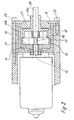
- the wheel arrangement is on a housing pot 10b arranged, which is inserted into the housing 10.
- the wheel arrangement is there from a sun gear 13, a or several stepped planet gears 17, the one in the central axis of the planetary gear support wheel 16, the input-side internally toothed Ring gear 14 and the output-side, also internally toothed ring gear 15.
- the drive pin 12 itself could be the sun gear of the planetary gear, in which it is toothed accordingly.
- the Housing is closed by an annular cover 11, the fastening screws 26 at the same time an outwardly angled flange of the housing pot Set 10b because this flange is between the face of the case 10 and the lid 11 is.
- a disc 27 stepped on the outer circumference, so that this is also fixed.
- the bore of the disk 27 is made by a hub 15a of the drive-side ring gear 15 permeated.
- Another output pin is in the bore of the support wheel 16 28 used non-rotatably.
- the support wheel 16 is located directly next to the sun wheel 13.
- the pitch circle diameter of the support wheel 16 is larger than that of the sun wheel 13. This results in correspondingly stepped planet gears 17. Accordingly, also the pitch circle diameter of the internal toothing of the drive-side ring gear 14 larger than that of the output-side ring gear 15. It results from FIG.
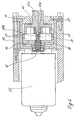
- the seamless planetary gear shown in Figures 3-7 are from one the drive pin 12 having an electric motor 29 driven.
- the drive pin 12 is provided with a toothing. Contrary to the illustration, the Drive pin 12 also the drive-side sun gear of a planetary gear rotatably put on.
- the drive-side is on the drive pin 12 by means of a bearing bush 30 Ring gear 14 mounted, which in the embodiment according to Figure 5 with the gearbox 10b is connected so that it is fixed.
- the housing pot 10b is closed in the gear housing 10 is used.
- the toothing of the drive pin 12 is in place with the planet gears 17 in engagement.
- the planet gears 17 are also stepped.
- the larger diameter areas form the first stage of the planetary gear and are with the internal toothing of the drive-side ring gear 14 in Intervention.
- the output-side ring gear 15 connects to the drive-side ring gear 14, which with the teeth with smaller diameters of the planet gears 17 in Intervention stands. In addition, these gears are with the one having a bore Jockey wheel 16 engaged.
- the drive pin extends 12 up to the facing surface of the support wheel 16.
- this support wheel 16 is mounted on a pin 15b on the Ring gear 15 is integrally formed.
- the ring gear 15 is also equipped with a cylindrical shoulder 15c.
- the assigned side of the gear housing 10 is by an annular cover 11 and a disc 27 closed.
- the pin 15b of the output side ring gear 15 forms the guide element in this embodiment.
- FIG. 3 clearly shows, the end of the Pin 15b designed to reduce friction spherical. This makes one extremely small area or a point contact between the adjacent Sharing achieved.
- the pin 15b is hemispherical Provide recess.
- a ball 31 which is made of Metal or plastic can be made, depending on what materials that drive-side ring gear 14 is made. Also through this ball 31, which is at Rotation of the motor pin 12 of the ring gear 15 can move freely, is the lowest possible Friction reached.
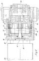
- the embodiment according to FIG. 5 differs essentially in that the pin 15b of the ring gear 15 and the cylindrical projection 15c as hollow parts are trained.
- the toothing of the drive-side ring gear is shortened, so that there is a gap between the two ring gears 14.
- This ring 32 with the one-piece bearing sleeve 33 are by a compression spring 34 loaded, which lies on the side facing away from the drive-side ring gear 14.
- This compression spring 34 also encompasses part of the output-side ring gear 15.
- the bearing sleeve 33 is movable in the axial direction. Even those with internal teeth of the output-side ring gear 15 meshing teeth Planet gears 17 are recessed in the area of the ring 32.
- this ring 32 agrees with the outer diameter of the output side ring gear 14 match.
- the ring 32 is also one Sealing ring 35 envelops.
- the compression spring 34 is supported on the one hand on the bearing sleeve 33 and on the other hand on an unspecified, connected to the gear housing 10 Attachment 36 from.
- the design and layout of this attachment 36 depends on the intended use of the planetary gear.
- the planetary gear shown in Figure 7 is the version of the figure 5 based on.
- the output-side ring gear 15 is a braking element 40 assigned, which interacts directly or indirectly with the ring gear 15 in order the planetary gear in one direction in a self-locking design shape.
- the braking element 40 is on Wrap spring brake element, which on the circumference of one with the output side Ring gear 18 acts firmly connected brake member 41.
- the wires of the wrap spring element from wires with square, preferably square cross sections. You wrap the brake member 41 uni given angle.
- This brake member 41 is with a coupling piece 42 firmly connected, which is rotatably mounted in an attachment 36.
- Non-rotatable with the coupling piece 42 is connected to a drive spindle 43.
- This drive spindle 43 can be a spindle with a pointed or trapezoidal thread, a ball screw or the like. Furthermore, could be between the coupling piece 42 and the Drive spindle 43 a switchable clutch can be interposed.
- FIG. 8 shows an embodiment of the planetary gear with a so-called Disengagement shown.
- This disengagement is necessary to make a component adjustment unit connected to the planetary gear at high speed lower.
- the ring gear 14 on the drive side can be rotated in the transmission housing 10 arranged. In the normal operating state, however, it is by a holding member settled.
- This holding member is in the illustrated embodiment from two opposing brake shoes 44 and 45, which are operated by controls 46, 47 brought out of contact with the drive-side, first ring gear 14 can be.
- the controls 46, 47 are designed so that the Brake shoes still apply a certain braking force to the drive-side ring gear 14 can, which regulates the lowering speed of the component can.
- the output-side ring gear 15 could by means of a externally actuated linkage brought out of engagement with the planet gears 17 be connected, for example by the disengagement already mentioned Lowering the component at a much higher speed than if this would take place with the motor 29 switched on.
- This release linkage could be spring loaded to engage the output side ring gear 15 again to bring the drive-side ring gear 14 and the planet gears 17.
- the output-side ring gear 15 could be opposite the axes of rotation of the drive pin 12 and the support wheel 16 may be offset or stand eccentrically.
- This planetary gear is also with one Planet gear 17 or equipped with several planet gears 17.
- the output side Ring gear 15 then performs an eccentric movement, for example in a linear float could be implemented. This makes the area of application of the planetary gear according to the invention further expanded. Essential are in these transmissions the stabilization of the support wheel 16 Components serving wheel arrangement.
Landscapes
- Engineering & Computer Science (AREA)
- General Engineering & Computer Science (AREA)
- Mechanical Engineering (AREA)
- Power Engineering (AREA)
- Retarders (AREA)
Abstract
Description
- Figur 1
- eine erste Ausführung des erfindungsgemäßen Planetengetriebes im vertikalen Schnitt,
- Figur 2
- ein zweites Ausführungsbeispiel des erfindungsgemäßen Planetengetriebes im vertikalen Schnitt,
- Figuren 3-7
- das erfindungsgemäße Planetengetriebe in fünf weiteren und verschiedenen Ausführungen,
- Figur 8
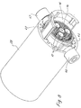
- den das Planetengetriebe antreibenden Motor in perspektivischer und aufgebrochener Darstellung mit Blick auf das antriebsseitige Hohlrad und die Planetenräder.
Claims (10)
Applications Claiming Priority (6)
| Application Number | Priority Date | Filing Date | Title |
|---|---|---|---|
| DE19806130 | 1998-02-14 | ||
| DE19806130 | 1998-02-14 | ||
| DE29816635U DE29816635U1 (de) | 1998-09-16 | 1998-09-16 | Stegloses Planetengetriebe |
| DE29816635U | 1998-09-16 | ||
| DE29816632U DE29816632U1 (de) | 1998-09-16 | 1998-09-16 | Stegloses Planetengetriebe |
| DE29816632U | 1998-09-16 |
Publications (2)
| Publication Number | Publication Date |
|---|---|
| EP0936379A2 true EP0936379A2 (de) | 1999-08-18 |
| EP0936379A3 EP0936379A3 (de) | 2001-12-12 |
Family
ID=27218143
Family Applications (1)
| Application Number | Title | Priority Date | Filing Date |
|---|---|---|---|
| EP99102519A Withdrawn EP0936379A3 (de) | 1998-02-14 | 1999-02-10 | Planetengetriebe |
Country Status (1)
| Country | Link |
|---|---|
| EP (1) | EP0936379A3 (de) |
Cited By (5)
| Publication number | Priority date | Publication date | Assignee | Title |
|---|---|---|---|---|
| EP1445191A1 (de) * | 2003-02-08 | 2004-08-11 | Jefa Steering ApS | Vorrichtung zum automatischen Steuern eines maritimen Fahrzeugs |
| WO2017216306A1 (de) * | 2016-06-16 | 2017-12-21 | Güdel Group AG | Planetengetriebe |
| DE102017112339A1 (de) | 2017-06-06 | 2018-08-09 | Schaeffler Technologies AG & Co. KG | Planetengetriebe mit mittels Sperrstift angebundenem Hohlrad sowie Antriebsachse mit Planetengetriebe |
| DE102018210604A1 (de) * | 2018-06-28 | 2019-07-25 | Magna powertrain gmbh & co kg | Getriebegehäuse zur Aufnahme eines Planetengetriebes |
| US12522278B2 (en) | 2021-06-04 | 2026-01-13 | Hl Mando Corporation | Steer by wire type steering apparatus |
Family Cites Families (4)
| Publication number | Priority date | Publication date | Assignee | Title |
|---|---|---|---|---|
| FR1073194A (fr) * | 1953-03-23 | 1954-09-20 | Réducteur de vitesse | |
| US3675510A (en) * | 1970-10-12 | 1972-07-11 | Anderson Duggar Jr | Speed reducer |
| IT1259059B (it) * | 1992-03-04 | 1996-03-11 | Vanni Gallocchio | Riduttore di velocita` |
| US5540630A (en) * | 1995-01-03 | 1996-07-30 | The United States Of America As Represented By The Administrator Of The National Aeronautics And Space Administration | Twist planet drive |
-
1999
- 1999-02-10 EP EP99102519A patent/EP0936379A3/de not_active Withdrawn
Non-Patent Citations (1)
| Title |
|---|
| None |
Cited By (8)
| Publication number | Priority date | Publication date | Assignee | Title |
|---|---|---|---|---|
| EP1445191A1 (de) * | 2003-02-08 | 2004-08-11 | Jefa Steering ApS | Vorrichtung zum automatischen Steuern eines maritimen Fahrzeugs |
| WO2017216306A1 (de) * | 2016-06-16 | 2017-12-21 | Güdel Group AG | Planetengetriebe |
| WO2017215758A1 (de) * | 2016-06-16 | 2017-12-21 | Güdel Group AG | Planetengetriebe |
| CN109563915A (zh) * | 2016-06-16 | 2019-04-02 | 固都集团股份公司 | 行星齿轮传动装置 |
| US10851885B2 (en) | 2016-06-16 | 2020-12-01 | Guedel Group Ag | Planetary transmission |
| DE102017112339A1 (de) | 2017-06-06 | 2018-08-09 | Schaeffler Technologies AG & Co. KG | Planetengetriebe mit mittels Sperrstift angebundenem Hohlrad sowie Antriebsachse mit Planetengetriebe |
| DE102018210604A1 (de) * | 2018-06-28 | 2019-07-25 | Magna powertrain gmbh & co kg | Getriebegehäuse zur Aufnahme eines Planetengetriebes |
| US12522278B2 (en) | 2021-06-04 | 2026-01-13 | Hl Mando Corporation | Steer by wire type steering apparatus |
Also Published As
| Publication number | Publication date |
|---|---|
| EP0936379A3 (de) | 2001-12-12 |
Similar Documents
| Publication | Publication Date | Title |
|---|---|---|
| EP0635658B1 (de) | Umlaufgetriebe mit Drehmomentbegrenzer und dessen Verwendung in Handwerkzeugen | |
| DE3787552T2 (de) | Zusatzgetriebe für Kraftfahrzeuge. | |
| WO2011104217A1 (de) | Schraubradgetriebe für eine lenkung eines kraftfahrzeugs | |
| EP2345569B1 (de) | Schraubradgetriebe für eine Lenkung eines Kraftfahrzeugs | |
| DE3815225A1 (de) | Sperrbares ausgleichsgetriebe | |
| DE10335193A1 (de) | Selektiv sperrbare Differentialbaugruppe für ein Kraftfahrzeug | |
| AT503001A2 (de) | Reibungskupplung mit aktuator und tellerfeder | |
| DE102008005229B4 (de) | Antriebseinrichtung | |
| DE102011108977B4 (de) | Aktuator, insbesondere für einenFahrzeugsitz | |
| EP4728208A1 (de) | Aktor zur bereitstellung eines drehmoments mit einem linearantrieb | |
| EP1557547B1 (de) | Stellvorrichtung | |
| EP1905147B1 (de) | Getriebemotor | |
| EP2228157A1 (de) | Elektromotorisch angetriebenes Schraub- oder Bohrwerkzeug | |
| DE202005017525U1 (de) | Reibungskupplung | |
| WO2001059331A1 (de) | Differentialgetriebe mit sperrkupplung und mit einer solchen ausgestattetes verteilergetriebe für kraftfahrzeuge | |
| EP0936379A2 (de) | Planetengetriebe | |
| DE4038226A1 (de) | Handgefuehrtes kraftdrehwerkzeug | |
| WO2022083982A1 (de) | Exzentergetriebe für einen bremskrafterzeuger, bremskrafterzeuger | |
| EP0281593B1 (de) | Getriebe mit überlast-sicherheitskupplung | |
| EP3682132A1 (de) | Freilaufkupplung mit reibungsinduzierter stellkraft | |
| DE102008061201A1 (de) | Mechanische, radial wirkende Rotationsarretierung | |
| WO2001090599A1 (de) | Vorrichtung zur umsetzung von rotationsbewegungen in linearbewegungen bzw. umgekehrt | |
| DE29816635U1 (de) | Stegloses Planetengetriebe | |
| EP1456552B1 (de) | Lastdrehmomentsperre | |
| EP0867640B1 (de) | Vorrichtung zur Umwandlung einer Dreh- in eine Axialbewegung |
Legal Events
| Date | Code | Title | Description |
|---|---|---|---|
| PUAI | Public reference made under article 153(3) epc to a published international application that has entered the european phase |
Free format text: ORIGINAL CODE: 0009012 |
|
| AK | Designated contracting states |
Kind code of ref document: A2 Designated state(s): AT BE CH CY DE DK ES FI FR GB GR IE IT LI LU MC NL PT SE Kind code of ref document: A2 Designated state(s): CH DE FR GB LI NL SE |
|
| AX | Request for extension of the european patent |
Free format text: AL;LT;LV;MK;RO;SI |
|
| RIN1 | Information on inventor provided before grant (corrected) |
Inventor name: PALM, DIETER DIPL.-ING. Inventor name: BOKAEMPER, RALF, DIPL.-ING. |
|
| RIC1 | Information provided on ipc code assigned before grant |
Free format text: 7F 16H 1/46 A, 7F 16H 1/28 B, 7F 16H 57/10 B, 7H 02K 7/116 B |
|
| PUAL | Search report despatched |
Free format text: ORIGINAL CODE: 0009013 |
|
| AK | Designated contracting states |
Kind code of ref document: A3 Designated state(s): AT BE CH CY DE DK ES FI FR GB GR IE IT LI LU MC NL PT SE |
|
| AX | Request for extension of the european patent |
Free format text: AL;LT;LV;MK;RO;SI |
|
| RAP1 | Party data changed (applicant data changed or rights of an application transferred) |
Owner name: RK ROSE + KRIEGER GMBH & CO. KG VERBINDUNGS- UND P |
|
| 17P | Request for examination filed |
Effective date: 20020610 |
|
| 17Q | First examination report despatched |
Effective date: 20020722 |
|
| AKX | Designation fees paid |
Free format text: CH DE FR GB LI NL SE |
|
| STAA | Information on the status of an ep patent application or granted ep patent |
Free format text: STATUS: THE APPLICATION HAS BEEN WITHDRAWN |
|
| 18W | Application withdrawn |
Effective date: 20040702 |