EP0936392A2 - Metallbalg und Metallbalg-Herstellungsverfahren - Google Patents
Metallbalg und Metallbalg-Herstellungsverfahren Download PDFInfo
- Publication number
- EP0936392A2 EP0936392A2 EP99103002A EP99103002A EP0936392A2 EP 0936392 A2 EP0936392 A2 EP 0936392A2 EP 99103002 A EP99103002 A EP 99103002A EP 99103002 A EP99103002 A EP 99103002A EP 0936392 A2 EP0936392 A2 EP 0936392A2
- Authority
- EP
- European Patent Office
- Prior art keywords
- bellows
- ring element
- blank
- deformation
- ring
- Prior art date
- Legal status (The legal status is an assumption and is not a legal conclusion. Google has not performed a legal analysis and makes no representation as to the accuracy of the status listed.)
- Withdrawn
Links
Images


Classifications
-
- F—MECHANICAL ENGINEERING; LIGHTING; HEATING; WEAPONS; BLASTING
- F16—ENGINEERING ELEMENTS AND UNITS; GENERAL MEASURES FOR PRODUCING AND MAINTAINING EFFECTIVE FUNCTIONING OF MACHINES OR INSTALLATIONS; THERMAL INSULATION IN GENERAL
- F16L—PIPES; JOINTS OR FITTINGS FOR PIPES; SUPPORTS FOR PIPES, CABLES OR PROTECTIVE TUBING; MEANS FOR THERMAL INSULATION IN GENERAL
- F16L23/00—Flanged joints
- F16L23/04—Flanged joints the flanges being connected by members tensioned in the radial plane
-
- F—MECHANICAL ENGINEERING; LIGHTING; HEATING; WEAPONS; BLASTING
- F16—ENGINEERING ELEMENTS AND UNITS; GENERAL MEASURES FOR PRODUCING AND MAINTAINING EFFECTIVE FUNCTIONING OF MACHINES OR INSTALLATIONS; THERMAL INSULATION IN GENERAL
- F16L—PIPES; JOINTS OR FITTINGS FOR PIPES; SUPPORTS FOR PIPES, CABLES OR PROTECTIVE TUBING; MEANS FOR THERMAL INSULATION IN GENERAL
- F16L25/00—Construction or details of pipe joints not provided for in, or of interest apart from, groups F16L13/00 - F16L23/00
- F16L25/0036—Joints for corrugated pipes
-
- F—MECHANICAL ENGINEERING; LIGHTING; HEATING; WEAPONS; BLASTING
- F16—ENGINEERING ELEMENTS AND UNITS; GENERAL MEASURES FOR PRODUCING AND MAINTAINING EFFECTIVE FUNCTIONING OF MACHINES OR INSTALLATIONS; THERMAL INSULATION IN GENERAL
- F16L—PIPES; JOINTS OR FITTINGS FOR PIPES; SUPPORTS FOR PIPES, CABLES OR PROTECTIVE TUBING; MEANS FOR THERMAL INSULATION IN GENERAL
- F16L27/00—Adjustable joints; Joints allowing movement
- F16L27/10—Adjustable joints; Joints allowing movement comprising a flexible connection only
- F16L27/107—Adjustable joints; Joints allowing movement comprising a flexible connection only the ends of the pipe being interconnected by a flexible sleeve
- F16L27/11—Adjustable joints; Joints allowing movement comprising a flexible connection only the ends of the pipe being interconnected by a flexible sleeve the sleeve having the form of a bellows with multiple corrugations
-
- F—MECHANICAL ENGINEERING; LIGHTING; HEATING; WEAPONS; BLASTING
- F16—ENGINEERING ELEMENTS AND UNITS; GENERAL MEASURES FOR PRODUCING AND MAINTAINING EFFECTIVE FUNCTIONING OF MACHINES OR INSTALLATIONS; THERMAL INSULATION IN GENERAL
- F16L—PIPES; JOINTS OR FITTINGS FOR PIPES; SUPPORTS FOR PIPES, CABLES OR PROTECTIVE TUBING; MEANS FOR THERMAL INSULATION IN GENERAL
- F16L51/00—Expansion-compensation arrangements for pipe-lines
- F16L51/02—Expansion-compensation arrangements for pipe-lines making use of a bellows or an expansible folded or corrugated tube
- F16L51/025—Expansion-compensation arrangements for pipe-lines making use of a bellows or an expansible folded or corrugated tube with several corrugations
Definitions
- the invention relates to a method for producing a compound with a suitable metal bellows counterpart, in which a tubular Blank by alternating force application to a bellows successive annular bulges and indentations deformed is, as well as a metal bellows produced by such a method.
- Metal bellows of the specified type are used for compensation in pipelines of thermal expansion, for sound absorption, for the isolation of pipe vibrations and to compensate for assembly tolerances.
- the metal bellows are usually with their end faces with each connected to a pipeline. Due to the stretchability or compressibility of the Metal bellows can then relative movements of the pipes to each other or different distances between these pipes be balanced.
- Typical areas of application for connecting pipes by means of metal bellows z. B. vacuum technology, thermal solar systems for domestic water heating and process heat generation, heating and hot water systems, process engineering systems, district heating pipes, Pipelines and energy systems.
- a ring element on a cylindrical end portion of a metal bellows postpone and then the metal bellows in its cylindrical Flare end area. Through the flared end of the metal bellows then prevents the ring member from the cylindrical end of the metal bellows can be deducted again. That in the manner mentioned on Metal bellows fixed ring element can then with a suitable counterpart, for example a counter flange attached to the pipeline connected by screws or clamps.
- a disadvantage of the described method for connecting metal bellows with piping is the fact that after manufacturing of the metal bellows the crimping process step is carried out must be to fix the ring element on the metal bellows. This Flanging process step is associated with economic effort, which makes the manufacturing process more expensive in an undesirable manner.
- An object of the invention is a method of connection to create a metal bellows with a counterpart, which with reduced Effort and, in particular, saving the procedural step of flanging can be carried out.
- the ring element is already before the manufacture of Metal bellows pushed onto the blank, whereupon the bellows generating deformation process begins.
- the ring element is used during of the deformation process so that it ultimately, after completion Production of the bellows between two neighboring bulges comes to rest and at least within these two bulges certain limits is fixed.
- the fixation of the ring element is ensured by the fact that the inner diameter of the ring element is smaller than the outer diameter of the bellows in the region of a bulge.
- the saving of flanging according to the invention ensures that a metal bellows with a ring element fixed to it in one Process step, namely by the deformation of the blank to the bellows can be manufactured, which has significant economic benefits brings.
- Fig. 1 shows a blank 1, which has the shape of a cylindrical tube having.
- the blank 1 can have circumferential beads that in the area of the indentations to be formed, in this way with the subsequent deformation larger diameter differences between indentations and bulges.
- ring element 4, 5 pushed. Both ring elements 4, 5 each have the same distance from the associated end 3, 2 of the blank 1 on.
- the inside diameter of the ring elements 4, 5 corresponds to essentially the outer diameter of the blank 1, but is so large that the ring elements 4, 5 without much effort on the blank 1st can be postponed.
- the blank 1 with the ring elements 4, 5 is then in a suitable Form introduced in which the deformation of the blank 1 to the bellows he follows.
- the deformation process mentioned can take place in that in Inside the blank 1 generates radially outward pressure forces at least in the area of the bellows indentations to be formed radially inward, caused by the shape mentioned Counter supporting forces. Due to the deformation of the blank 1 to Bellows is naturally a shortening of the blank 1 or the bellows, because for the formation of the bellows bulges, the wall of the blank 1 what must be pressed out in the corresponding areas then inevitably an axial contraction or a shortening of the Blank 1 causes. This shortening is due to that shown in FIGS. 2 to 4 Metal bellows recognizable. To the deformation process of the above Shortening must take into account the shape that the radial inward support forces also shorten or contract. Such shapes are from the prior art known.
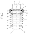
- Fig. 2 shows a metal bellows produced according to the invention with several alternating successive annular bulges 6 and Indentations 7. From FIG. 2 it can be seen that the ring elements 4, 5 1 were positioned on the blank 1 such that after deformation of the blank to the bellows, the ring elements 4, 5 each between two Bulges 8, 9 and 10, 11 in one between these bulges 8, 9 and 10, 11 arranged indentation 12 and 13 come to rest. The ring elements 4, 5 are thus through the bulges 8, 9 or 10, 11 fixed in their position at least so far that they do not have the mentioned bulges can be pushed away.
- the bellows 2 facing the end face and on the ring element 5 adjacent bulge 11 represents the last bulge of the bellows in Direction of the mentioned bellows end 2. It behaves accordingly with the bulge assigned to the opposite bell-end 3 8th.
- the respective last bulge 11 or 8 in the direction of the front bellows end 2 or 3 each represents a complete wave, which means that it merges in the direction of the respective bellows end 2, 3 into a region of an indentation 14 or 15.
- any other form of the last bulge 11 can also be realized.
- the last bulge it is possible for the last bulge to have a different shape than the bulges located between the ring elements.
- the outer diameter of the last bulge can be larger or smaller than the outer diameter of the bulges located between the ring elements, the last bulge can in particular merge into a cylindrical bellows closure via an indentation or it can end with a substantially radially extending wall of the bulge.
- the coupling of a bellows according to FIG. 2 with a counterpart 16 is exemplary shown in the area of the bellows end 2.
- a corresponding Coupling is provided in the area of the opposite bellows end 3. This coupling is - just like in FIGS. 3 and 4 - for the sake of Clarity not shown.
- the counterpart 16 consists of a ring element whose inner diameter corresponds to that of the ring elements 4, 5 and that with a Housing or pipe section 17 is connected.
- the last bulge 11 in the direction of the bellows end 2 is between Ring element 5 and the counterpart 16 arranged, wherein ring element 5th and counterpart 16 by a bracket element 19 towards each other to be pulled, so that ultimately the bulge 11 between the ring element 5 and the counterpart 16 is clamped.
- annular Sealant 20 is provided, which on the bulge 11 is present. This sealant 20 creates a tight connection made between metal bellows and pipe section 17.
- FIG. 3 shows an alternative method for producing a connection to FIG. 2 between a metal bellows and a piece of pipe. Those Parts of FIG. 3 that find a correspondence in FIG. 2 are respectively marked with the same reference numerals.
- FIG. 4 shows a further variant of the invention, elements here also which find their correspondence in FIGS. 2 and 3, with the same reference numerals are designated.
- the metal bellows according to FIG. 4 is also produced in the same way like the metal bellows according to FIGS. 2 and 3. There is only one difference in that after the production of the metal bellows, the last bulge in each case towards a bellows end in the area of their largest diameter is cut off.
- Ring elements 4, 5 and counterparts 16, 21, 23 can also be any other way as shown in FIGS. 2 to 4.
- For example can be used as a flange, support ring for union nuts, ring with external thread or the like. Accordingly, too the connection of ring element 5 and counterpart 16, 21, 23 to others Way as done by means of the bracket 19. In particular, too Screw connections possible.
- the metal bellows can be produced in such a way that the ring elements 4, 5 after the deformation of the blank 1 with its radially inner Form-fitting surfaces, especially clamping in the ring-shaped indentations 12, 13 are present.
- the ring elements 4, 5 with their end faces on the two, the ring elements 4, 5 adjacent bulges 8, 9 and 10, 11th concern, especially pinched between these bulges are.
Landscapes
- Engineering & Computer Science (AREA)
- General Engineering & Computer Science (AREA)
- Mechanical Engineering (AREA)
- Diaphragms And Bellows (AREA)
Abstract
Description
- Fig. 1
- einen Rohling mit zwei aufgeschobenen Ringelementen,
- Fig. 2
- eine nach einer ersten Variante des erfindungsgemäßen Verfahrens hergestellte Metallbalg-Rohrverbindung,
- Fig. 3
- eine nach der zweiten Variante des erfindungsgemäßen Verfahrens hergestellte Metallbalg-Rohrverbindung, und
- Fig. 4
- eine nach der dritten Variante des erfindungsgemäßen Verfahrens hergestellte Metallbalg-Rohrverbindung.
Es sind jedoch auch beliebige andere Ausformungen der letzten Ausbuchtung 11 realisierbar. Insbesondere ist es möglich, daß die letzte Ausbuchtung eine andere Form aufweist als die zwischen den Ringelementen gelegenen Ausbuchtungen. Zum Beispiel kann der Außendurchmesser der letzten Ausbuchtung größer oder kleiner sein als der Außendurchmesser der zwischen den Ringelementen gelegenen Ausbuchtungen, die letzte Ausbuchtung kann insbesondere über eine Einbuchtung in einen zylindrischen Balgabschluß übergehen oder sie kann mit einer im wesentlichen radial verlaufenden Wand der Ausbuchtung enden.
Claims (10)
- Verfahren zur Herstellung eines zur Verbindung mit einem Gegenstück (16, 21, 23) geeigneten Metallbalgs, bei dem ein rohrförmiger Rohling (1) durch Kraftbeaufschlagung zu einem Balg mit mehreren alternierend aufeinanderfolgenden ringförmigen Aus- und Einbuchtungen (6, 7) deformiert wird,
dadurch gekennzeichnet,daß zumindest ein zur Verbindung mit dem Gegenstück (16, 21, 23) dienendes Ringelement (4, 5) relativ zum Rohling (1) derart angeordnet wird, daß es diesen umgibt, unddaß anschließend die Deformation des Rohlings (1) zum Balg derart erfolgt, daß das Ringelement (4, 5) in einer ringförmigen Einbuchtung (12, 13) zwischen zwei benachbarten Ausbuchtungen (8, 9; 10, 11) zu liegen kommt. - Verfahren nach Anspruch 1,
dadurch gekennzeichnet,daß die Deformation innerhalb einer Form erfolgt, wobei im Inneren des Rohlings (1) radial nach außen gerichtete Druckkräfte erzeugt werden, denen zumindest im Bereich der Einbuchtungen (7) des zu erzeugenden Balgs radial nach innen gerichtete, durch die Form bewirkte Stützkräfte entgegenwirken, wobei insbesondere das Ringelement (4, 5) während der Deformation ebenfalls radial nach innen gerichtete Stützkräfte bedingt und/oder das Ringelement (4, 5) vor der Deformation in die Form eingelegt und der Rohling (1) anschließend durch das Ringelement (4, 5) geschoben und auf diese Weise in die Form eingelegt wird, oderdaß das Ringelement (4, 5) vor der Deformation auf den Rohling (1) geschoben anschließend gemeinsam mit dem Rohling (1) in die Form eingelegt wird. - Verfahren nach einem der vorhergehenden Ansprüche,
dadurch gekennzeichnet,
daß die einem stirnseitigen Balgende (2, 3) zugewandte und an das Ringelement (4, 5) angrenzende Ausbuchtung (8, 11) die letzte Ausbuchtung des Balgs in Richtung des stirnseitigen Balgendes (3, 2) ist und das stirnseitige Balgende (3, 2) durch einen Bereich einer Einbuchtung (14, 15) und/oder durch einen zylindrischen Balgabschluß gebildet ist, wobei insbesondere die in Richtung des stirnseitigen Balgendes (2, 3) gelegene letzte Ausbuchtung (8, 11) zwischen dem Ringelement (4, 5) und dem Gegenstück (16, 21, 23) aufnehmbar ist. - Verfahren nach Anspruch 5,
dadurch gekennzeichnet,
daß nach Herstellung des Balgs die zwischen dem Ringelement (4, 5) und dem Gegenstück (16, 21, 23) aufnehmbare Ausbuchtung (8, 11) bei Verbindung von Ringelement (4, 5) und Gegenstück (16, 21, 23) in Axialrichtung des Balgs deformierbar und zwischen Ringelement (4, 5) und Gegenstück (16, 21, 23) klemmbar ist, oder daß während Herstellung des Balgs die zwischen dem Ringelement (4, 5) und dem Gegenstück (16, 21, 23) aufnehmbare Ausbuchtung (8, 11) insbesondere durch bewegliche Elemente der Form in Axialrichtung des Balgs deformiert, vorzugsweise zusammengedrückt wird. - Verfahren nach Anspruch 4,
dadurch gekennzeichnet,
daß die Deformation hauptsächlich in dem der Balgachse zugewandten Bereich der Ausbuchtung (8, 11) erfolgt, wobei insbesondere die Deformation derart erfolgt, daß sich die beiden, sich im wesentlichen radial erstreckenden Wände der Ausbuchtung (8, 11) in dem der Balgachse zugewandten Bereich der Ausbuchtung (8, 11) berühren. - Verfahren nach den Ansprüchen 1 bis 3,
dadurch gekennzeichnet,
daß der Balg nach der Ausformung der Ein- und Ausbuchtungen (6, 7) im Bereich seiner in Richtung des stirnseitigen Balgendes (2, 3) gelegenen letzten Ausbuchtung (8, 11) abgeschnitten wird. - Verfahren nach einem der vorhergehenden Ansprüche,
dadurch gekennzeichnet,
daß Ringelement (4, 5) und Form derart bemessen sind, daß das Ringelement (4, 5) nach der Deformation des Rohlings (1) mit seiner radial innen liegenden Fläche formschlüssig, insbesondere klemmend, an der ringförmigen Einbuchtung (12, 13) anliegt, und/oder daß Ringelement (4, 5) und Form derart bemessen sind, daß das Ringelement (4,5) nach der Deformation des Rohlings (1) mit seinen Stirnflächen an den beiden, dem Ringelement (4, 5) benachbarten Ausbuchtungen (8, 9; 10, 11) anliegt, insbesondere zwischen den beiden Ausbuchtungen (8, 9; 10, 11) eingeklemmt ist. - Verfahren nach einem der vorhergehenden Ansprüche,
dadurch gekennzeichnet,
daß Ringelement (4, 5) und Form derart bemessen sind, daß das Ringelement (4, 5) nach der Deformation des Rohlings (1) im Bereich der ringförmigen Einbuchtung (12, 13) bezogen auf die Längsachse des Balgs axial verschiebbar und/oder drehbar ist, und/oder daß zwei Ringelemente (4, 5) relativ zum Rohling (1) derart angeordnet werden, daß sie diesen insbesondere in seinen beiden einander gegenüberliegenden Endbereichen umgeben. - Metallbalg, hergestellt nach einem Verfahren gemäß einem der vorhergehenden Ansprüche.
- Metallbalg nach Anspruch 9,
dadurch gekennzeichnet,
daß das Ringelement bzw. die Ringelemente (4, 5) und/oder das Gegenstück bzw. die Gegenstücke (16, 21, 23) ein ebenfalls ringförmiges Dichtungsmittel (20) aufweisen, und/oder daß das Ringelement bzw. die Ringelemente (4, 5) als Flansch, Stützring für Überwurfmuttern, Ring mit Außengewinde oder dgl. ausgebildet sind.
Applications Claiming Priority (2)
| Application Number | Priority Date | Filing Date | Title |
|---|---|---|---|
| DE1998106304 DE19806304A1 (de) | 1998-02-16 | 1998-02-16 | Metallbalg und Metallbalg-Herstellungsverfahren |
| DE19806304 | 1998-02-16 |
Publications (2)
| Publication Number | Publication Date |
|---|---|
| EP0936392A2 true EP0936392A2 (de) | 1999-08-18 |
| EP0936392A3 EP0936392A3 (de) | 2001-02-14 |
Family
ID=7857859
Family Applications (1)
| Application Number | Title | Priority Date | Filing Date |
|---|---|---|---|
| EP99103002A Withdrawn EP0936392A3 (de) | 1998-02-16 | 1999-02-15 | Metallbalg und Metallbalg-Herstellungsverfahren |
Country Status (2)
| Country | Link |
|---|---|
| EP (1) | EP0936392A3 (de) |
| DE (1) | DE19806304A1 (de) |
Cited By (5)
| Publication number | Priority date | Publication date | Assignee | Title |
|---|---|---|---|---|
| DE102005024413A1 (de) * | 2005-05-27 | 2006-12-07 | Airbus Deutschland Gmbh | Verbindungsstück zur gelenkigen Verbindung einer ersten und einer zweiten Rohrleitung |
| DE102008021326A1 (de) | 2007-05-18 | 2008-11-20 | Scania Cv Ab | Flexible Rohrkupplung |
| DE102014112559A1 (de) | 2014-09-01 | 2016-03-03 | Christian Becker | Leitungselement einer Zuführleitung einer Brennkraftmaschine eines Kraftfahrzeuges und Verfahren zur Herstellung eines solchen Leitungselementes |
| CN111536356A (zh) * | 2020-04-28 | 2020-08-14 | 江苏赛尔超高压特种管业有限公司 | 一种新型玻纤增强热塑性塑料管及其生产工艺 |
| CN111720639A (zh) * | 2020-06-02 | 2020-09-29 | 台州市涌星贸易有限公司 | 一种高耐压pfa波纹管 |
Families Citing this family (2)
| Publication number | Priority date | Publication date | Assignee | Title |
|---|---|---|---|---|
| DE10065573A1 (de) * | 2000-12-28 | 2002-07-04 | Brugg Rohrsysteme Gmbh | Verfahren zum Umbördeln des Endes eines schraubenlinienförmig gewellten Rohres |
| CN107088599A (zh) * | 2017-05-06 | 2017-08-25 | 芜湖瑞德机械科技有限公司 | 一种不锈钢管打波机 |
Family Cites Families (15)
| Publication number | Priority date | Publication date | Assignee | Title |
|---|---|---|---|---|
| US1366473A (en) * | 1914-04-22 | 1921-01-25 | Harry C Mallory | Expansible and collapsible element for thermostatic and pressuresensitive devices |
| US1656213A (en) * | 1920-08-31 | 1928-01-17 | American Radiator Co | Method of producing expansible-collapsible elements |
| US1727281A (en) * | 1921-10-17 | 1929-09-03 | Fulton Sylphon Co | Method of making flexible corrugated tubular walls |
| US1870904A (en) * | 1930-08-02 | 1932-08-09 | Fulton Sylphon Co | Attachment of heads to bellows |
| US2014355A (en) * | 1933-02-27 | 1935-09-10 | United States Gypsum Co | Vibration isolating pipe connection |
| US2196676A (en) * | 1937-09-23 | 1940-04-09 | Chicago Metal Hose Corp | Flexible connector |
| US2965961A (en) * | 1948-02-13 | 1960-12-27 | Flexonics Corp | Method of making a reinforced flexible conduit assembly |
| US2818636A (en) * | 1949-05-26 | 1958-01-07 | Chicago Metal Hose Corp | Method of manufacturing reinforced flexible conduit |
| US2832613A (en) * | 1954-06-10 | 1958-04-29 | Flexonics Corp | Autogenous welded laminated expansion joint for conduits |
| DE7030864U (de) * | 1970-08-18 | 1970-12-17 | Eiff Ulrich Christof Von | Verbindung fuer eine leitung |
| FR2672373B1 (fr) * | 1991-01-31 | 1993-10-15 | Hubschen Alfred | Perfectionnements dans la realisation des elements de raccordement utilises dans les installations a faire le vide. |
| DE9209274U1 (de) * | 1992-02-24 | 1992-10-08 | Witzenmann GmbH, Metallschlauch-Fabrik Pforzheim, 7530 Pforzheim | Anordnung zum Montieren eines Anschlußelementes |
| DE4205537A1 (de) * | 1992-02-24 | 1993-08-26 | Witzenmann Metallschlauchfab | Verfahren zum montieren eines anschlusselementes |
| DE9420502U1 (de) * | 1994-11-30 | 1995-07-20 | Witzenmann GmbH, Metallschlauch-Fabrik Pforzheim, 75175 Pforzheim | Anschlußverbindung zwischen einem Rohr und einem rohrförmigen Leitungselement |
| DE29606683U1 (de) * | 1996-04-12 | 1997-08-14 | Witzenmann GmbH Metallschlauch-Fabrik Pforzheim, 75175 Pforzheim | Anschlußverbindung zwischen einem Bauteil und einem rohrförmigen Leitungselement |
-
1998
- 1998-02-16 DE DE1998106304 patent/DE19806304A1/de not_active Ceased
-
1999
- 1999-02-15 EP EP99103002A patent/EP0936392A3/de not_active Withdrawn
Cited By (7)
| Publication number | Priority date | Publication date | Assignee | Title |
|---|---|---|---|---|
| DE102005024413A1 (de) * | 2005-05-27 | 2006-12-07 | Airbus Deutschland Gmbh | Verbindungsstück zur gelenkigen Verbindung einer ersten und einer zweiten Rohrleitung |
| US7677606B2 (en) | 2005-05-27 | 2010-03-16 | Airbus Deutschland Gmbh | Connector for an articulated connection of a first and second pipeline |
| DE102005024413B4 (de) * | 2005-05-27 | 2011-01-27 | Airbus Operations Gmbh | Verbindungsstück zur gelenkigen Verbindung einer ersten und einer zweiten Rohrleitung |
| DE102008021326A1 (de) | 2007-05-18 | 2008-11-20 | Scania Cv Ab | Flexible Rohrkupplung |
| DE102014112559A1 (de) | 2014-09-01 | 2016-03-03 | Christian Becker | Leitungselement einer Zuführleitung einer Brennkraftmaschine eines Kraftfahrzeuges und Verfahren zur Herstellung eines solchen Leitungselementes |
| CN111536356A (zh) * | 2020-04-28 | 2020-08-14 | 江苏赛尔超高压特种管业有限公司 | 一种新型玻纤增强热塑性塑料管及其生产工艺 |
| CN111720639A (zh) * | 2020-06-02 | 2020-09-29 | 台州市涌星贸易有限公司 | 一种高耐压pfa波纹管 |
Also Published As
| Publication number | Publication date |
|---|---|
| DE19806304A1 (de) | 1999-08-19 |
| EP0936392A3 (de) | 2001-02-14 |
Similar Documents
| Publication | Publication Date | Title |
|---|---|---|
| DE69000739T2 (de) | Verfahren zur herstellung einer abdichtungsverbindung zwischen hartrohren und damit hergestellte rohrverbindung. | |
| EP2893241B1 (de) | Fitting, system mit einem solchen fitting und dichte verbindung mit einem solchen fitting | |
| DE3317061A1 (de) | Flanschverbindungsanordnung | |
| EP0589413B1 (de) | Zum Anschliessen eines Endabschnittes eines Rohres vorgesehene Anschlussvorrichtung | |
| DE3508296C2 (de) | Rohrverbindung | |
| DE19647553C2 (de) | Verbindung eines dünnen Metallrohres kleinen Durchmessers mit einem Gummi-Druckschlauch und Verfahren zur Herstellung dieser Verbindung | |
| EP1707861B1 (de) | Fitting und Verfahren zur Herstellung eines Fittings | |
| DE19520099C2 (de) | Rohrverbindung und Verfahren zu ihrer Herstellung | |
| EP0936392A2 (de) | Metallbalg und Metallbalg-Herstellungsverfahren | |
| EP1907742B1 (de) | Biegbarer schlauch sowie verfahren zum montieren einer überwurfmutter auf einen biegbaren schlauch | |
| EP2205371B1 (de) | Verfahren zur herstellung von rohr-in-rohr-systemen | |
| EP3135976A1 (de) | Verbindungsanordnung für wellrohrschlauchleitungen | |
| EP0222855B1 (de) | Verfahren zur herstellung eines schlauchnippels für hydraulisch belastete press- oder schraubarmaturen | |
| DE19757946C2 (de) | Rohrverbindung | |
| WO1996035526A1 (de) | Presswerkzeug und verfahren zum verbinden von rohrförmigen elementen | |
| DE102012003146B4 (de) | Schlauchverbindung und Verfahren zur Herstellung einer Schlauchverbindung | |
| DE19815244A1 (de) | Verfahren und Vorrichtung zum Herstellen von metallischen Hohlkörpern mit Beul-Struktur | |
| DE3029621A1 (de) | Form- und nutvorrichtung fuer rohrenden | |
| DE102007036205B4 (de) | Verfahren zum Herstellen einer luftspaltisolierten Rohreinheit und Abgasrohreinheit | |
| DE19526085A1 (de) | Gelenkige Verbindung zweier Rohre einer Abgasanlage | |
| EP3760329B1 (de) | Verfahren zur herstellung eines schlauchnippels | |
| WO1997043572A1 (de) | Schlauchanschluss und verfahren zu dessen herstellung | |
| DE4022722C2 (de) | ||
| EP1483521B1 (de) | Rohrverbindung | |
| DE29623072U1 (de) | Schlauchanschluß |
Legal Events
| Date | Code | Title | Description |
|---|---|---|---|
| PUAI | Public reference made under article 153(3) epc to a published international application that has entered the european phase |
Free format text: ORIGINAL CODE: 0009012 |
|
| AK | Designated contracting states |
Kind code of ref document: A2 Designated state(s): AT BE CH CY DE DK ES FI FR GB GR IE IT LI LU MC NL PT SE |
|
| AX | Request for extension of the european patent |
Free format text: AL;LT;LV;MK;RO;SI |
|
| PUAL | Search report despatched |
Free format text: ORIGINAL CODE: 0009013 |
|
| AK | Designated contracting states |
Kind code of ref document: A3 Designated state(s): AT BE CH CY DE DK ES FI FR GB GR IE IT LI LU MC NL PT SE |
|
| AX | Request for extension of the european patent |
Free format text: AL;LT;LV;MK;RO;SI |
|
| RIC1 | Information provided on ipc code assigned before grant |
Free format text: 7F 16L 27/11 A, 7F 16L 51/02 B, 7B 21D 15/06 B, 7F 16L 25/00 B |
|
| AKX | Designation fees paid | ||
| PUAJ | Public notification under rule 129 epc |
Free format text: ORIGINAL CODE: 0009425 |
|
| REG | Reference to a national code |
Ref country code: DE Ref legal event code: 8566 |
|
| PUAJ | Public notification under rule 129 epc |
Free format text: ORIGINAL CODE: 0009425 |
|
| STAA | Information on the status of an ep patent application or granted ep patent |
Free format text: STATUS: THE APPLICATION IS DEEMED TO BE WITHDRAWN |
|
| 18D | Application deemed to be withdrawn |
Effective date: 20010815 |