EP0936411A2 - Montagesystem für Glaskeramik-kochplatten - Google Patents
Montagesystem für Glaskeramik-kochplatten Download PDFInfo
- Publication number
- EP0936411A2 EP0936411A2 EP99500019A EP99500019A EP0936411A2 EP 0936411 A2 EP0936411 A2 EP 0936411A2 EP 99500019 A EP99500019 A EP 99500019A EP 99500019 A EP99500019 A EP 99500019A EP 0936411 A2 EP0936411 A2 EP 0936411A2
- Authority
- EP
- European Patent Office
- Prior art keywords
- glass
- ceramic
- frame
- silicone
- ceramic glass
- Prior art date
- Legal status (The legal status is an assumption and is not a legal conclusion. Google has not performed a legal analysis and makes no representation as to the accuracy of the status listed.)
- Withdrawn
Links
- 238000010411 cooking Methods 0.000 title claims abstract description 35
- 239000002241 glass-ceramic Substances 0.000 title claims abstract description 17
- 239000000919 ceramic Substances 0.000 claims abstract description 82
- 239000011521 glass Substances 0.000 claims abstract description 82
- 238000010438 heat treatment Methods 0.000 claims abstract description 20
- 229920001296 polysiloxane Polymers 0.000 claims description 42
- 238000007789 sealing Methods 0.000 claims description 19
- 229920002323 Silicone foam Polymers 0.000 claims description 10
- 239000013514 silicone foam Substances 0.000 claims description 10
- 230000006978 adaptation Effects 0.000 claims description 4
- 239000007788 liquid Substances 0.000 claims description 4
- 239000000463 material Substances 0.000 claims description 4
- 238000004140 cleaning Methods 0.000 description 4
- 238000009434 installation Methods 0.000 description 4
- 239000012530 fluid Substances 0.000 description 2
- 238000009825 accumulation Methods 0.000 description 1
- 230000000295 complement effect Effects 0.000 description 1
- 238000001914 filtration Methods 0.000 description 1
- 239000002245 particle Substances 0.000 description 1
- 230000002035 prolonged effect Effects 0.000 description 1
- 238000004080 punching Methods 0.000 description 1
- 238000010079 rubber tapping Methods 0.000 description 1
- 238000007493 shaping process Methods 0.000 description 1
Images
Classifications
-
- F—MECHANICAL ENGINEERING; LIGHTING; HEATING; WEAPONS; BLASTING
- F24—HEATING; RANGES; VENTILATING
- F24C—DOMESTIC STOVES OR RANGES ; DETAILS OF DOMESTIC STOVES OR RANGES, OF GENERAL APPLICATION
- F24C15/00—Details
- F24C15/10—Tops, e.g. hot plates; Rings
- F24C15/108—Mounting of hot plate on worktop
-
- H—ELECTRICITY
- H05—ELECTRIC TECHNIQUES NOT OTHERWISE PROVIDED FOR
- H05B—ELECTRIC HEATING; ELECTRIC LIGHT SOURCES NOT OTHERWISE PROVIDED FOR; CIRCUIT ARRANGEMENTS FOR ELECTRIC LIGHT SOURCES, IN GENERAL
- H05B3/00—Ohmic-resistance heating
- H05B3/68—Heating arrangements specially adapted for cooking plates or analogous hot-plates
- H05B3/74—Non-metallic plates, e.g. vitroceramic, ceramic or glassceramic hobs, also including power or control circuits
Definitions
- the following invention consists on an assembly system for glass-ceramic cooking plates, which are made up of the beautifying frame that acts as a support of all the whole and besides as a beautifying element, the tray for the location of the heating elements and the rest of the components of control and function and the ceramic glass, being all of them joined, shaping the glass-ceramic for its installation into the corresponding cavity of the worktop.
- the present assembly system for glass-ceramic plates is especially applicable with the frame for ceramic glasses described in the Invention Patent P9700351 of the same applicant which described and claimed a frame with a perimetral gable formed by a profile that defines a closed perimetral frame and a curved upper elvowing to the exterior of the frame, whose upper branch, of convex extemal surface, is prolonged to the exterior of the frame for being finished off with regard to the inner part of the gable, so that the tray of the heating elements will be fixed to the gable of the frame and the ceramic glass will be perimetrally leaned on the upper prolongation of the elbowing of the profile of the frame.
- the assembly system is based on the joining of the profile of the frame with the tray where the heating elements and the rest of the components of control and function are placed, and on the location of the ceramic glass with regard to the tray and the frame, so that from this generic execution, the material way of carrying it out can change.
- the presented assembled system is for the assembly of glass-ceramic cooking plates that essentially are formed by the frame, which besides acts as a support of the whole and as a beautifying element, the tray for the location of the heating elements and the ceramic glass, so that once the whole is assembled, it will be installed into the respective cavity made in the worktop.
- the applicant of the present dossier is also the applicant of the Invention Patent P9201348 in which some "Improvements in the support plate for the cooking ceramic glass" are claimed, which are basically based on realizing a punching in the vertexes of the seat base of the ceramic glass in the inlayed plate, in order to when there is a partial loosening of a particle of the same vertex, the same one remains under the support plan of the ceramic glass in relationship to its seat base.
- the support plate of the ceramic glass can be manufactured by inlaying without very marked angles that can cause its break by the accumulation of stretchings in some points such as the vertexes.
- an assembly system for cooking glass-ceramic plates is described, being of the kind of those cooking plates that have a frame which acts as a support of the whole of the plate and besides as a beautifying element in its fitting into the cavity of the piece of furniture where it is installed, so that it is formed by the perimetral frame which has the means for the subjection of a tray for the assembly of the heating elements and the rest of components, the means of support of the ceramic glass and the means of tightness of the frame in relationship to the piece of furniture of fitting and the own ceramic glass.
- the means for the subjection of the assembly tray of the heating elements and the rest of the components of control and function are defined by a set of inlayings done in the perimetral gable of the profile of the frame, which remain centrally open for materializing the fixing by means of the respective screws and nuts, which pass through the central opening of the inlayings and through holes in the lateral walls of the own tray of assembly of the heating elements.
- the support means of the ceramic glass are defined by a perimetral scaling to the exterior of the lateral walls of the tray on which the ceramic glass is placed with the interposition of the corresponding sealing cord of silicone.
- each sealing cords made of silicone, silicone foam or some similar material, that are manually or automatically incorporated on the intemal side of the wings relative to the beautifying stretch, once the frame has been configurated.
- the support frame of the whole of the cooking plate is directly joined through its gable to the tray of assembly of the heating elements and the rest of components, since this tray has a U-shaped upper projecting with horizontal wings, so that it is joined to the gable for its fixing, remaining the ceramic glass leaned on the upper wing of the cited projecting with an U-shaped profile, with the interposition of a sealing cord of silicone, silicone foam or a similar element, while into the hollow defined in the intemal side of the beaytifying stretch of the profile of the frame, it is placed a sealing liquid which flows for covering all the hollow.
- the ceramic glass For the assembly of the ceramic glass, it is perimetrally surrounded by a silicone joint with a C-shaped general section, remaining its lower wing leaned on the upper wing of the U-shaped projecting of the tray of assembly of the heating elements, while its upper wing remains under the intemal wing of the stretch of the beautifying element of the profile of the frame.
- the silicone joint that perimetrally surroundes the ceramic glass with a C-shaped general transverse section, has its lower wing longer than its upper wing which is finished off by an adittion of thickness which remains under the intemal wing of the beautifying stretch of the frame, in order to do tight the ceramic glass in the inner part of the cooking plate.
- the silicone joint that perimetrally surroundes the ceramic glass with a C-shaped general transverse section has its lower wing longer than its upper wing, having a concavity in the side of joining next to the ceramic glass, so that the upper surface of the upper wing has some little projectings which remain under the intemal wing of the stretch of the beautifying element of the frame, in order to obtain the tightness between the ceramic glass and the interior of the cooking plate.
- the silicone joint that perimetrally surroundes the ceramic glass with a C-shaped general transverse section, has its wings with the same length and there is a concavity defined in the side of joining to the lateral of the ceramic glass, so that both wings of the silicone joint have, in the external surface, some little projectings for making their adaptation easy and obtaining the tightness of the ceramic glass.
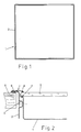
- Figure 1. It shows a plan view of the profile that shapes the closed frame according to an intemal view, where it is observed the gable before the embodiment of the inlayings for the fastening of the tray for the location of the heating elements and the rest of the components of control and function, so that the ceramic glass first will be placed perimetrally leaned on the intemal prolongation of the beautifying element of the profile that defines the stretch.
- Figure 2. It shows a detailed sectioned view of the way of fastening of the tray where the heating elements of the cooking plate and the rest of components necessary for its working are assembled with the frame where they are screwed in relationship to a set of open inlayings, and the location of the ceramic glass and the own piece of fumiture on the worktop of the kitchen in which it is fitted into the corresponding cavity.
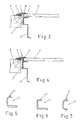
- Figure 3. It shows a sectioned detailed view of the way of assembly and installation of the cooking plate according to a variant of execution where the tray of assembly of the heating elements of the cooking plate is fixed to the gable of the profile of the frame, so that the tray defines a seat for a flange bent to the interior and the ceramic glass is leaned on the cited seat with the interposition of a sealing element while in relationship to the intemal wing of the beautifying element, there is a levelling element defined by a fluid sealing liquid.
- Figure 4. It shows a sectioned detailed view of the way of assembly and installation of the cooking plate accordinging to a variant of execution where, in relationship to the perimetral edge of the ceramic glass, it is placed a silicone joint with a C-shaped general section surrounding the same one, si that it remains placed on the bent upper flange of the tray where the heating elements and the rest of components are assembled.
- Figure 5. It shows a sectioned view of a silicone joint for surrounding the ceramic glass perimetrally, which has a C-shaped general form with its lower wing of bigger length and with some little projectings in its upper wing.
- Figure 6. It shows a sectioned view of a silicone joint for surrounding the ceramic glass perimetrally, which has a C-shaped general form with its lower wing of bigger length with an addition of thickness that finished off its upper wing of less length.
- Figure 7. It shows a sectioned view of a silicone joint for surrounding the ceramic glass perimetrally, which has a C-shaped general form with the same length in its wings and being endowed of some little projectings.
- the ceramic glass (5) is placed on a upper scaling of the lateral walls of the tray (4) of assembly of the heating elements with the interposition of a sealing cord (7) of silicone, silicone foam or other similar element at the same time that the upper perimetral edge of the cited ceramic glass remains hidden under the intemal wing of the upper part of the beautifying element of the frame, with the interposition of the corresponding sealing cord (8) of silicone, silicone foam or a similar element.
- the frame (1) can lack of the cited cord (9) of silicone, so that at the moment of the assembly, the worker can place, perimetrally to the seat of the frame on the piece of fumiture, an strip of gum for boing the same function as a tightness element.
- one ot two cords of silicone can be placed on the own metallic frame configurated and this operation can be done at the same time or separately, so that the cited cords of silicone, silicone foam or a similar element placed on the intemal sides of the wings relative to the beautifying element of the frame, can be incorporated manually or automatically.
- the frame (1) of the cooking plate is directly fixed through its gable (2) to the tray (4), since this tray has a U-shaped upper projecting with horizontal wings and it is joined to the gable (2) of the frame (1) for its fixing, so that the upper wing defines a seat on which the sealing element (7) of silicone, silicone foam or other similar material is placed, while into the hollow defined by the internal wing of the beautifying element of the profile (1) it is placed a fluid sealing liquid (3) which makes its levelling easy and can flow easily to the lateral of the ceramic glass (5).
- a sealing cord (9) of silicone, silicone foam or other similar element will be placed, while the tightness with the ceramic glass (5) is obtained by the sealing element (10) previously cited which flows filling all the hollow defined by the intemal side of the intemal side of the beautifying stretch of the profile (1).
- the ceramic glass (5) will remain perimetrally surrounded by a silicone joint (11) with a C-shaped general transverse section, so that in its assembly, it is placed like a sandwich between the beautifying element of the frame (1) and the tray (4) for the assembly of the heating elements and the rest of the components of control and function for the correct working of the apparatus.
- the joint (11) of silicone can present a C-shaped general section with its lower wing shorter than its upper wing, on whose upper surface there are some little projectings (12) that will allow an easy retraction and adaptation to the intemal wing of the profile of the beautifying frame for obtaining a perfect tightness with regard to the ceramic glass (5), while its intemal part has a concavity that allows its adaptation to the lateral of the ceramic glass since the glass has a similar convex lateral surface.
- the joint (11) of silicone can have a C-shaped general section with the same length in its wings, which are endowed of some little projectings (12) in relationship to the external surface of its two wings, in order to obtain a perfect adaptability in its seat on the tray (4) and on the internal wing of the profile of the beautifying frame.
Landscapes
- Engineering & Computer Science (AREA)
- Chemical & Material Sciences (AREA)
- Combustion & Propulsion (AREA)
- Mechanical Engineering (AREA)
- General Engineering & Computer Science (AREA)
- Ceramic Engineering (AREA)
- Re-Forming, After-Treatment, Cutting And Transporting Of Glass Products (AREA)
- Baking, Grill, Roasting (AREA)
- Control Of Resistance Heating (AREA)
- Electric Stoves And Ranges (AREA)
- Table Equipment (AREA)
Applications Claiming Priority (2)
| Application Number | Priority Date | Filing Date | Title |
|---|---|---|---|
| ES9800278A ES2156661B1 (es) | 1998-02-12 | 1998-02-12 | Sistema de montaje de placas vitroceramicas de coccion |
| ES9800278 | 1998-02-12 |
Publications (2)
| Publication Number | Publication Date |
|---|---|
| EP0936411A2 true EP0936411A2 (de) | 1999-08-18 |
| EP0936411A3 EP0936411A3 (de) | 2000-04-12 |
Family
ID=8302726
Family Applications (1)
| Application Number | Title | Priority Date | Filing Date |
|---|---|---|---|
| EP99500019A Withdrawn EP0936411A3 (de) | 1998-02-12 | 1999-01-29 | Montagesystem für Glaskeramik-kochplatten |
Country Status (2)
| Country | Link |
|---|---|
| EP (1) | EP0936411A3 (de) |
| ES (1) | ES2156661B1 (de) |
Cited By (4)
| Publication number | Priority date | Publication date | Assignee | Title |
|---|---|---|---|---|
| WO2003071192A1 (de) * | 2002-02-22 | 2003-08-28 | Schott Glas | Kochsystem |
| EP1325666A4 (de) * | 2000-08-18 | 2007-03-21 | Luxine Inc | Induktionserwärmungs- und steuersystem und verfahren mit hoher zuverlässigkeit und fortgeschrittenen leistungsmerkmalen |
| ITUA20162298A1 (it) * | 2016-04-05 | 2017-10-05 | Donnini S R L S | Dispositivo di fissaggio di una lastra in vetroceramica di un piano cottura |
| EP4517189A1 (de) * | 2023-08-28 | 2025-03-05 | Electrolux Appliances Aktiebolag | Kochfeld |
Citations (1)
| Publication number | Priority date | Publication date | Assignee | Title |
|---|---|---|---|---|
| DE3441281A1 (de) * | 1984-11-12 | 1986-05-22 | Bosch-Siemens Hausgeräte GmbH, 7000 Stuttgart | Kochmulde |
Family Cites Families (3)
| Publication number | Priority date | Publication date | Assignee | Title |
|---|---|---|---|---|
| DE4210010C2 (de) * | 1992-03-27 | 1995-04-27 | Schott Glaswerke | Kochfeldplatte |
| GB2277146B (en) * | 1993-04-08 | 1996-08-28 | Chef Australia Pty Ltd | Hot plate support frame |
| DE4329956C2 (de) * | 1993-09-04 | 1996-08-14 | Schott Glaswerke | Anordnung zur Halterung eines Einbaukochfeldes |
-
1998
- 1998-02-12 ES ES9800278A patent/ES2156661B1/es not_active Expired - Fee Related
-
1999
- 1999-01-29 EP EP99500019A patent/EP0936411A3/de not_active Withdrawn
Patent Citations (1)
| Publication number | Priority date | Publication date | Assignee | Title |
|---|---|---|---|---|
| DE3441281A1 (de) * | 1984-11-12 | 1986-05-22 | Bosch-Siemens Hausgeräte GmbH, 7000 Stuttgart | Kochmulde |
Cited By (6)
| Publication number | Priority date | Publication date | Assignee | Title |
|---|---|---|---|---|
| EP1325666A4 (de) * | 2000-08-18 | 2007-03-21 | Luxine Inc | Induktionserwärmungs- und steuersystem und verfahren mit hoher zuverlässigkeit und fortgeschrittenen leistungsmerkmalen |
| US8803048B2 (en) | 2000-08-18 | 2014-08-12 | The Vollrath Company, L.L.C. | Induction heating and control system and method with high reliability and advanced performance features |
| WO2003071192A1 (de) * | 2002-02-22 | 2003-08-28 | Schott Glas | Kochsystem |
| ITUA20162298A1 (it) * | 2016-04-05 | 2017-10-05 | Donnini S R L S | Dispositivo di fissaggio di una lastra in vetroceramica di un piano cottura |
| EP4517189A1 (de) * | 2023-08-28 | 2025-03-05 | Electrolux Appliances Aktiebolag | Kochfeld |
| WO2025045524A1 (en) * | 2023-08-28 | 2025-03-06 | Electrolux Appliances Aktiebolag | Cooking hob |
Also Published As
| Publication number | Publication date |
|---|---|
| ES2156661B1 (es) | 2002-02-16 |
| EP0936411A3 (de) | 2000-04-12 |
| ES2156661A1 (es) | 2001-07-01 |
Similar Documents
| Publication | Publication Date | Title |
|---|---|---|
| JP5255037B2 (ja) | 成形周辺封止部を備える封入型ウインドウアセンブリ | |
| US5317129A (en) | Cooking range | |
| US4453533A (en) | Frame for plates of glass, vitreous ceramic or similar material, particularly for cooker hobs | |
| US5185047A (en) | Frameless glass-ceramic cooktop mounting assembly | |
| US7281715B2 (en) | Cooktop gasket | |
| US5036831A (en) | Frameless glass-ceramic cooktop mounting assembly | |
| MXPA06010567A (es) | Cubiculo de ducha y base. | |
| US5785047A (en) | Cooktop or hob top including a planar panel interlocked to an outboard frame by an injection molded encapsulation having injection molded encapsulation having integral fasteners | |
| US6410891B1 (en) | Cooking unit, such as a stove, for cooking food | |
| US5429114A (en) | Cooktop unit for mounting in a frame structure or a cutout | |
| DE10041006C2 (de) | Glas- oder Glaskeramikscheibe mit einem Kantenschutz und Verfahren zu ihrer Herstellung | |
| US20100155387A1 (en) | Hotplate cooker cover for said cooker and method for production of the hotplate and cover | |
| US6588326B2 (en) | Cooking station with a glass-ceramic bowl having a sunken curved heating surface | |
| CN210125518U (zh) | 一种电热锅及其面盖组件 | |
| EP0860660A1 (de) | Montagesystem für Kochplatten | |
| EP0860661A1 (de) | Rahmen für Glaskeramikplatte und Verfahren zur Herstellung desselben | |
| US6399183B1 (en) | Plate made of glass material | |
| CN222149652U (zh) | 一种烹饪机器人 | |
| CN202960088U (zh) | 一种密封防漏的电水壶 | |
| CN206354883U (zh) | 蒸汽阀及烹饪器具 | |
| CN216454616U (zh) | 饮料机用分体式出液盘 | |
| CN218295835U (zh) | 用于灶具的辅助安装结构及集成灶 | |
| CN215638285U (zh) | 抗变形冰箱隐形门盖 | |
| US7229577B2 (en) | Method for forming a bathtub liner | |
| CN223886818U (zh) | 一种洗碗机 |
Legal Events
| Date | Code | Title | Description |
|---|---|---|---|
| PUAI | Public reference made under article 153(3) epc to a published international application that has entered the european phase |
Free format text: ORIGINAL CODE: 0009012 |
|
| AK | Designated contracting states |
Kind code of ref document: A2 Designated state(s): DE ES FR GB GR IT NL SE |
|
| AX | Request for extension of the european patent |
Free format text: AL;LT;LV;MK;RO;SI |
|
| PUAL | Search report despatched |
Free format text: ORIGINAL CODE: 0009013 |
|
| AK | Designated contracting states |
Kind code of ref document: A3 Designated state(s): AT BE CH CY DE DK ES FI FR GB GR IE IT LI LU MC NL PT SE |
|
| AX | Request for extension of the european patent |
Free format text: AL;LT;LV;MK;RO;SI |
|
| RAP1 | Party data changed (applicant data changed or rights of an application transferred) |
Owner name: BSH BALAY, S.A. |
|
| 17P | Request for examination filed |
Effective date: 20000912 |
|
| AKX | Designation fees paid |
Free format text: DE ES FR GB GR IT NL SE |
|
| 17Q | First examination report despatched |
Effective date: 20021126 |
|
| STAA | Information on the status of an ep patent application or granted ep patent |
Free format text: STATUS: THE APPLICATION IS DEEMED TO BE WITHDRAWN |
|
| 18D | Application deemed to be withdrawn |
Effective date: 20040211 |