EP0936433B1 - Patronen-Zuführeinrichtung für eine Mehrlade-Handfeuerwaffe - Google Patents
Patronen-Zuführeinrichtung für eine Mehrlade-Handfeuerwaffe Download PDFInfo
- Publication number
- EP0936433B1 EP0936433B1 EP98123904A EP98123904A EP0936433B1 EP 0936433 B1 EP0936433 B1 EP 0936433B1 EP 98123904 A EP98123904 A EP 98123904A EP 98123904 A EP98123904 A EP 98123904A EP 0936433 B1 EP0936433 B1 EP 0936433B1
- Authority
- EP
- European Patent Office
- Prior art keywords
- cartridge
- magazine
- feed mechanism
- mechanism according
- feed
- Prior art date
- Legal status (The legal status is an assumption and is not a legal conclusion. Google has not performed a legal analysis and makes no representation as to the accuracy of the status listed.)
- Expired - Lifetime
Links
- 238000012546 transfer Methods 0.000 claims abstract description 14
- 230000001960 triggered effect Effects 0.000 claims description 2
- 238000004146 energy storage Methods 0.000 claims 3
- 230000007935 neutral effect Effects 0.000 claims 2
- 230000006835 compression Effects 0.000 description 5
- 238000007906 compression Methods 0.000 description 5
- 230000000295 complement effect Effects 0.000 description 3
- 230000002996 emotional effect Effects 0.000 description 3
- 238000010276 construction Methods 0.000 description 2
- 238000000034 method Methods 0.000 description 2
- 230000008569 process Effects 0.000 description 2
- RTAQQCXQSZGOHL-UHFFFAOYSA-N Titanium Chemical compound [Ti] RTAQQCXQSZGOHL-UHFFFAOYSA-N 0.000 description 1
- 230000009471 action Effects 0.000 description 1
- 238000013459 approach Methods 0.000 description 1
- 230000004888 barrier function Effects 0.000 description 1
- 230000008901 benefit Effects 0.000 description 1
- 210000000078 claw Anatomy 0.000 description 1
- 238000013461 design Methods 0.000 description 1
- 238000011161 development Methods 0.000 description 1
- 230000000694 effects Effects 0.000 description 1
- 210000002414 leg Anatomy 0.000 description 1
- 238000012545 processing Methods 0.000 description 1
- 229910052719 titanium Inorganic materials 0.000 description 1
- 239000010936 titanium Substances 0.000 description 1
- 238000012549 training Methods 0.000 description 1
- 230000007704 transition Effects 0.000 description 1
- 210000000689 upper leg Anatomy 0.000 description 1
Images



Classifications
-
- F—MECHANICAL ENGINEERING; LIGHTING; HEATING; WEAPONS; BLASTING
- F41—WEAPONS
- F41A—FUNCTIONAL FEATURES OR DETAILS COMMON TO BOTH SMALLARMS AND ORDNANCE, e.g. CANNONS; MOUNTINGS FOR SMALLARMS OR ORDNANCE
- F41A9/00—Feeding or loading of ammunition; Magazines; Guiding means for the extracting of cartridges
- F41A9/61—Magazines
- F41A9/64—Magazines for unbelted ammunition
- F41A9/65—Box magazines having a cartridge follower
- F41A9/70—Arrangements thereon for discharging, e.g. cartridge followers or discharge throats
-
- F—MECHANICAL ENGINEERING; LIGHTING; HEATING; WEAPONS; BLASTING
- F41—WEAPONS
- F41A—FUNCTIONAL FEATURES OR DETAILS COMMON TO BOTH SMALLARMS AND ORDNANCE, e.g. CANNONS; MOUNTINGS FOR SMALLARMS OR ORDNANCE
- F41A9/00—Feeding or loading of ammunition; Magazines; Guiding means for the extracting of cartridges
- F41A9/01—Feeding of unbelted ammunition
- F41A9/06—Feeding of unbelted ammunition using cyclically moving conveyors, i.e. conveyors having ammunition pusher or carrier elements which are emptied or disengaged from the ammunition during the return stroke
- F41A9/09—Movable ammunition carriers or loading trays, e.g. for feeding from magazines
- F41A9/10—Movable ammunition carriers or loading trays, e.g. for feeding from magazines pivoting or swinging
- F41A9/13—Movable ammunition carriers or loading trays, e.g. for feeding from magazines pivoting or swinging in a vertical plane
- F41A9/16—Movable ammunition carriers or loading trays, e.g. for feeding from magazines pivoting or swinging in a vertical plane which is parallel to the barrel axis
- F41A9/17—Movable ammunition carriers or loading trays, e.g. for feeding from magazines pivoting or swinging in a vertical plane which is parallel to the barrel axis mounted within a smallarm
- F41A9/19—Movable ammunition carriers or loading trays, e.g. for feeding from magazines pivoting or swinging in a vertical plane which is parallel to the barrel axis mounted within a smallarm feeding from a tubular magazine mounted in the stock
Definitions
- the invention relates to a cartridge feeder for a multi-load handgun with one barrel and one Movable closure is equipped and the characteristics according to the preamble of claim 1 contains.
- the one Transition station forms. If the shutter is opened, then the cartridge is ejected first and then, when the lock is almost open, the lifting block becomes as far as moved up so that the cartridge is now in its Feeding station sits exactly behind the cartridge chamber. At the Closing the lock runs from behind into the Hole and pushes the cartridge straight into Chamber. Just before the closure closes the lifting block jumps down again. Since the Receiving hole has a slot on the top, which corresponds to the width of the closure, the Lift block can be moved down, although the Closure penetrates the location hole.
- This generic feeder is not unproblematic because the closure head is a smaller one Diameter than the location hole must have if one the above advantage of the minimum length of the weapon wants to use.
- a Tube magazine usually a Tube magazine required.
- the invention is the Task based on the generic feeding device to further develop that side by side Tracking cartridges are brought to a transfer station who are in alignment behind the chamber.
- the cartridge is therefore not, as in the prior art, in the longitudinal direction of the weapon, but in the transverse direction in the Supported intermediate station.
- the direction of conveyance from the Transfer station to the intermediate station is thus how So far, in the direction of the cartridges, but this Tracking direction takes place transversely to the longitudinal direction, what through the conveyor according to the invention and by the Design of the lifting device is achieved.
- the transfer station is preferably located under the Intermediate station, so the weapon is not overly large Receives dimensions in the transverse direction.
- a magazine is whole in the sense of the invention generally understood a tracking device, even if this by the closing movement or by a separate drive device is operated, such as a de-belting device.
- the magazine is preferred equipped with a spring-loaded feeder and designed as a plate or rod magazine, the can in turn be one or more rows. Further a single-row rod magazine is preferred, the given the large cartridge dimensions for which the Feed device according to the invention primarily determined is due to the resulting magazine dimensions on is most appropriate.
- the movable magazine lip can be resilient, for example be trained and provided with an attack element be on which a functional part of the weapon can attack to to bend the magazine lip out of its rest position; however, the movable one is preferred Magazine lip around the top cartridge in one position agile in which it is between the top and the subsequent cartridge can intervene to do this to act as a barrier at the same time, which is the advancement of subsequent cartridge prevented.
- the movable Magazine lip preferably be designed as a bracket, the two Has thighs on the front and back of the Magazine is pivotally mounted.
- released Cartridge into the liner from the lock movement driven element may be provided; acts preferentially however, after unlocking the feeder of the magazine directly or via the subsequent cartridge so on the top cartridge that this up to or almost into the Intermediate station is promoted.
- the movable magazine lip is preferably in the direction their rest position so spring loaded that they are the top Cartridge can be used to promote it in the Intermediate layer to perform, support and / or finish.
- the two magazine lips are movable, while the other is fixed and has an inner contour that is complementary to Outer contour of the cartridges; the fixed The magazine lip ends above the movable magazine lip, so that the cartridge is not vertical, but transverse to it Longitudinal direction, is fed obliquely upwards; this Training facilitates the function of the moving Magazine lip as a lock for the subsequent cartridge.
- the lifting device could have resilient claws on the cartridge in the intermediate station be clipped, this up into the feed station take away and in the feed station from the closure be bent apart when this the cartridge in the Cartridge introduces the barrel.
- the lifting device is designed as a feed fork, which has two tines, with which it the in the Intermediate cartridge on both sides from below and reaches under and then lifts up.
- Such Feed fork is not only very light, it does not grip disturbing in other functional elements of the weapon and inclines not to pollute, what with military weapons used is particularly advantageous.
- the feed fork could move in unevenly long swivel levers; is preferred however, they are movable in a backdrop, so that even a complicated movement in the smallest space can be controlled.
- the forks are included Complementary to the shape of the cartridge so designed that it in the feed station always coaxial to the core axis is aligned.
- the cartridge can only then the feed station take when the shutter is open; therefore are at the generic feeder on the shutter two edges or catches formed when reaching the feed station from the front or the rear Operate the feed device.
- the closure must be in front and a movement distance behind the feed station cover, but according to the invention just minimized shall be. Therefore, in a further embodiment suggested that to drive at least the feed fork and at least on their way from the intermediate station to the Feeding station from the closure at the return (at the Movement through the feed station) applied force is used, but is introduced into an energy store and is only delivered to the feed fork when the The shutter is open and stands still. If the Conveyor fork is so short that it is not up to reaches the rear end of the feed station Forward movement of the closure when inserting the Cartridge in the cartridge chamber can be used immediately to swing the feed fork down before locking and bring it back to the starting position.
- This energy store is also preferred used to operate the conveyor, whose Then work with the lock open and at a standstill can be done.
- one Ensuring trouble-free operation is one Catch device provided for the closure, which this in holds its rearmost position and then only the Passing on the driving force from the energy store to the Feeding device or parts thereof are permitted if the Catcher has fallen into the lock and it this ensures that it is in its open position is held.
- the feeding process is at least largely completed, then controls the Feeder the catcher and sets the Closure released again.
- the rifle partially shown in Fig. 1 is a Large-caliber self-loading rifle with a barrel 25 made of titanium, which is mounted in a longitudinally movable manner in a weapon housing 24, pressed into its forward position by a running spring 22.
- the Pipe presses the locking lever 6 out of engagement Control shaft 2.
- a breech sits behind the barrel a locking head 20 which is rotatable in a behind it located closure bracket 21 is attached and with the Barrel 25 can engage in locking engagement.
- the Lock carrier is by a closing spring device 23rd burdened forward, which in turn with one designated oil pressure damper.
- a catch lever 8 is under the path of movement of the closure carrier 21st attached and can engage with it to him to hold in its rearmost position (shown in Fig. 2).
- the Cartridge for such a rifle with a very sensitive, equipped with electronic elements Projectile can be provided so that the projectile at Reloading not on any obstacles that may otherwise come up with self-loading weapons Pole magazine are provided for the purpose of putting the floor in an angled movement path from the magazine into the Cartridge tracking, the kinking all the more takes place more drastically, the shorter the for tracking The available route is and the larger the route which must be covered by the cartridge.
- the hollow control shaft 2 which is open at the rear, plunges from behind a pull rod 3 with circumferential play and extends themselves up to near their front end. Between the front End of the tie rod 3 and the inside of the control shaft 2 at its rear end is a helical one, around which Drawbar 3 inserted compression spring 4 used.
- the rear end of the tie rod 3 protrudes rearward from the Control shaft 2 out and is on a driver 5 attached to the back of the fastener carrier 21st is attached and extends downward from this.
- the fastener carrier 21 moves rearward, takes he the pull rod 4 to the rear with the driver 5, which in turn either control shaft 2 via the Compression spring 4 takes or if this at the Backward movement is inhibited, the compression spring 4 loaded and squeeze.
- a slot 17 (shown in the 3a to 3m) into which a control pin 11 intervenes, which in turn is stationary on the weapon housing 24 is appropriate.
- the backdrop groove 17 extends in her front section straight and parallel to Direction of movement of barrel 25, breech 20, 21 and Control shaft 2, and in its rear section points it a closed loop, which is designed such that the control pin 11 in the forward and backward movement the control shaft 2 each by a separate arm Loop runs through. Will the control shaft advance and moved back, then the backdrop 17 runs at the fixed Control pin 11 along and and leads one to her Longitudinal movement each assigned rotary movement.
- the magazine 14 is a single-row bar magazine with one sitting down, up through the magazine spring loaded feeder that pushes the cartridges up.
- the magazine 14 has a fixed magazine lip, which is up from one side of the magazine arched towards the center of the magazine, the curvature runs complementary to the contour of a cartridge. They do above-mentioned movable magazine lip 16 lies below the top edge of the fixed magazine lip on the other Magazine sidewall and can go down and to Magazine center are pivoted.
- the filling opening for the cartridge is therefore not in the middle, but on the side offset at the top of magazine 14.
- a feed fork 10 is provided as the lifting device, the longitudinally displaceable and by pivoting with your rear end can be raised below the barrel 25 at height of the cartridge chamber is arranged.
- the feed fork 10 shown in FIG. 7 has two parallel prongs 31, which are in Extend the longitudinal direction (top view) of the weapon in a straight line, but are so curved in the side view that a rear section parallel to a front section Section extends, but opposite this upwards is offset.
- the rear, free ends of the tines 31 are tapered and rounded to reach under a cartridge to facilitate.
- the front ends of the tines 31 are through a laterally protruding fork pin 29 connected; further back, but still at the front section, they are two tines 31 connected by a cross bar 30.
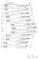
- the fork pin 29 and the cross bar 30 are at the front and backward movement of the feed fork 10 so positively guided as is illustrated by the scenes shown in FIG. 6 are shown; these scenes do not need to be built be present but can be through other elements be replaced.
- the tines 31 and the scenes or Movements in association with the fork pin 29 and Cross bar 30 formed so that in the front position or Starting position of the feed fork 10 whose rear, free ends below at least the floor and in front of this the behind her cartridge in the intermediate station lie in the rear position or end position against the rear portions of the tines 31 the cartridge full reach under and hold it in a position in which it can find itself behind the cartridge chamber and exactly coaxial to it located (shown on the right in Fig. 2 and Fig. 6). It is the exact shape of the tines 31 to the geometry of the cartridge adjusted so that their coaxial position to the cartridge chamber is guaranteed.
- control piece 1 already mentioned sits rotatably, however axially immovable at the front end of the control shaft 2, extends it forward and thus follows it Longitudinal movement, but not their rotational movement.
- the cylindrical control piece 1 has in its outside two essentially extending in the longitudinal direction Setting grooves, namely the control groove 27 and Fork groove 28.
- the control groove 27 extends to front end of control piece 1 and runs in one widened mouth while the fork groove 28 before the front end of the control piece 1 with a widened, forward-opening section ends.
- the Control groove 27 temporarily engages a fixed on the weapon housing attached control pin 12, while in the fork groove 28 the fork pin 29 engages and is guided.
- the basic position shown in Fig. 1 corresponds the representations of FIGS. 3a and 3m.
- the magazine 14 in that shown in Fig. 4b Position in which the top cartridge against the curved Inside the stationary magazine lip and against it movable magazine lip in its uppermost position 16 is present.
- the magazine 14 also takes this position outside the weapon.
- the feed fork 10 is in the in Fig. 6 position shown on the left.
- the control piece 1 with the Control shaft 2 is in its foremost position.
- the Drawbar 3 is in its foremost position; the Compression spring 4 is relaxed.
- the closure 20, 21 is located himself in his foremost position. If a cartridge is in the Cartridge chamber is located, it can be shot down.
- the Control link 17 sits with its rear end on the stationary control pin 11, the control groove 27 sits with its rear end on the stationary control pin 12, and the fork groove 28 sits with its rear end on the Fork pin 29 on.
- the cartridge If the cartridge is fired, then how moves described initially, first the barrel 25 together with the Closure head 20 and the closure carrier 21 to the rear; is loaded by hand, then the barrel remains 25 in its foremost location.
- the driver 5 moves with the Lock carrier 21 to the rear and pulls the pull rod 3 to the rear, which in turn via the compression spring 4 Control shaft 2 and the control piece 1 takes until the Control shaft 2 with the heart around which the loop of the Control link 17 runs around, against the stationary Control pin 11 runs up. Since the rear unlocking arm 7 is held by the catch piece 8 and in turn rotatably sits on the control shaft 2, this can not twist and remains stationary, while the closure 20, 21st continues to run back and the driver 5 and tie rod 3 Compress spring 4.
- the control groove 27 and the Fork groove 28 run in relation to the stationary control pin 12 and the fork pin 29, which for the time being is also stationary remains, to the rear.
- the closure carrier 21 reaches its rearmost position, the Catch piece 8 falls into this and gives the rear Release arm 7 free.
- the control shaft 2 is again rotatable and can be with the centerpiece under the rear, Swivel the stationary control pin 11 away, into the loop the control link 17 arrives.
- the two of them Unlocking arms 7 pivoted, which in turn the movable magazine lip 16 pivot down so that the top cartridge in magazine 14 is released and the subsequent is held (Fig. 5a).
- the full cartridge (when loading by hand) or the empty cartridge case (after the shot) is thrown out. If the Has been triggered by a shot just before the run 25 forward again emotional.
- the pull rod 3 has together with the driver 5 and the Closure carrier 21 reaches its rear end position: the further backward movement of control piece 1 and control shaft 2 is by the compressed spring 4 by their Relaxation.
- the loop of the control link 17 is just over the fixed control pin 11 run away; the Control shaft 2 pivots in the opposite direction preceding, but over a larger angular range carried out.
- the unlocking arms 7 therefore also pivot over back an angular distance that is greater than that before covered angular distance, and the moving Magazine lip 16 swings back into its starting position (not because it is stopped by an attack there).
- the top cartridge in magazine 14, previously from the pivoted magazine lip 16 was reached meanwhile from the next cartridge or the magazine feeder due to the action of the magazine spring pushed up and is now by the effect of Magazine spring, supported by the spring, not shown movable magazine lip 16, moved upwards (FIG. 5b), until it has reached the intermediate station (Fig. 5c).
- the next cartridge now takes the top layer in magazine 14 on. A bulge of the gun case against the Fixed magazine lip enables the tracked Cartridge, past the stationary magazine lip upwards to be moved.
- control shaft 2 With the further backward movement of the control shaft 2 runs the rear control pin 11 in the front, straight Section of the control link 17, the direction of movement the control shaft runs in parallel, and the control shaft 2 will therefore not move further backwards twisted further.
- the control piece 1 runs with the front, chamfered end of the fork groove 28 against the fork pin 29 and can twist as the control groove 27 of the control piece 1 with its enlarged inlet above the front, fixed control pin 12 which is the Rotation of the control piece 1 within the extended Approved path allows.
- the control shaft 2 runs together with the control piece 1 further back, the fork pin 29 via the fork groove 28 takes the feed fork 10 to the rear.
- the feed fork 10 runs with its cross bar 30 a backdrop along (see Fig. 6), engages under with its tines 31 cartridge in the intermediate station and lifts it upwards, almost up to the top layer, which in 6 is shown on the right.
- the control edge 13 takes the control shaft 2 with the contact piece 9.
- the control piece 1 moves further back and lifts the feed fork 10 completely on.
- the cartridge has reaches the feed station, i.e. the position shown in FIG is shown.
- the switching piece 9 pivots the catch lever 8 the engagement in the closure carrier 21 and this begins, to run forward together with the locking head 20.
- the Control piece 1 and the control shaft 2 reach their rearmost position.
- the movements of the closure head 20 and Control fork 10 are coordinated so that the already moving forward closure head 20 the bottom of the Cartridge has almost reached its feed station reached.
- the breech head 20 has reached the bottom of the cartridge and begins to push it forward while the Feed fork 10 still remains in its uppermost position; this is possible because the tines 31 of the feed fork 10 are not reach back to the bottom of the cartridge.
- the firm on Closure carrier 21 attached driver 5 strikes the end edge of the control shaft 2 and pushes it Forward.
- the rear end of the fork groove widening 28 runs onto the fork pin 29 and begins this to take along with the feed fork 10 to the front.
- the feed fork 10 is the fork groove 28 of the Control 1 forward at speed with which the closure head 20 moved forward with the cartridge; the tines 31 swing with their rear ends down until the feed fork 10 again its initial position (Fig. 6 left) occupies.
- the bullet tip of the cartridge dips into that Cartridge chamber.
- the control piece 1 runs with the Extension of the control groove 27 against the front, stationary Control pin 12 on.
- the cartridge is fully inserted into the chamber and the shutter head 20 is locked while the Lock carrier 21 around the locking distance to the front emotional.
- the control link 17 runs at its heart rear, stationary control pin 11 over and runs with their slightly curved end on this so that the Control shaft 2 performs a slight rotation in which the rear unlocking arm 7 again in engagement with the Catch lever 8 arrives.
Landscapes
- Engineering & Computer Science (AREA)
- General Engineering & Computer Science (AREA)
- Portable Nailing Machines And Staplers (AREA)
- Toys (AREA)
- De-Stacking Of Articles (AREA)
- Packages (AREA)
- Packaging Of Annular Or Rod-Shaped Articles, Wearing Apparel, Cassettes, Or The Like (AREA)
- Warehouses Or Storage Devices (AREA)
- Specific Conveyance Elements (AREA)
- Replacement Of Web Rolls (AREA)
Description
Claims (12)
- Patronen-Zuführeinrichtung für eine Mehrlade-Handfeuerwaffe, die mit einem Lauf (25) und einem beweglichen Verschluß (20, 21) ausgestattet ist, mita) einem Magazin (14) zum Heranführen von Patronen von unten oder von der Seite her,b) einer Umsetzeinrichtung zum Freigeben und Fördern der herangeführten Patrone in eine Zwischenstation, undc) einer Hubeinrichtung (10) zum Fördern der Patrone aus der Zwischenstation in eine Zuführstation, in der sich die Patrone hinter dem Patronenlager des Laufes (25) befindet, dadurch gekennzeichnet, daß die Hubeinrichtung (10) in Richtung der Laufachse längsbeweglich ist und die Patrone in der Zwischenstation unterfängt.
- Patronen-Zuführeinrichtung nach Anspruch 1 , dadurch gekennzeichnet, daß das Magazin (14) einen federbelasteten Zubringer aufweist und bevorzugt als Stangenmagazin ausgebildet ist.
- Patronen-Zuführeinrichtung nach Anspruch 2, dadurch gekennzeichnet, daß die Umsetzeinrichtung mit mindestens einer beweglichen Magazinlippe (16) zusammenwirkt, die zum Freisetzen der obersten Patrone aus einer Ruhelage beweglich mit dem Verschluß (20, 21) gekoppelt ist, und daß eine Sperre vorgesehen ist, die das Nachrücken einer weiteren Patrone verhindert.
- Patronen-Zuführeinrichtung nach Anspruch 3, dadurch gekennzeichnet, daß die bewegliche Magazinlippe (16) bis in eine Lage beweglich ist, in der sie als Sperre gegenüber dem Nachrücken einer weiteren Patrone wirksam ist.
- Patronen-Zuführeinrichtung nach Anspruch 3, dadurch gekennzeichnet, daß die von der beweglichen Magazinlippe (16) freigegebene Patrone durch den Zubringer nach Aufheben der Sperre bis in die Zwischenstation verbringbar ist.
- Patronen-Zuführeinrichtung nach einem der Ansprüche 2 oder 5, dadurch gekennzeichnet, daß die bewegliche Magazinlippe (16) durch eine Federeinrichtung in Richtung ihrer Ruhelage belastet ist.
- Patronen-Zuführeinrichtung nach einem der Ansprüche 3 bis 6, dadurch gekennzeichnet, daß nur eine einzige bewegliche Magazinlippe (16) vorgesehen ist, und daß die dieser gegenüberliegende feste Magazinlippe komplementär zur obersten Patrone nach oben bis in eine Höhe über der beweglichen Magazinlippe (16) gewölbt ist.
- Patronen-Zuführeinrichtung nach einem der Ansprüche 1 bis 7, dadurch gekennzeichnet, daß die Hubeinrichtung als Zuführgabel (10) mit zwei Zinken (31) ausgebildet ist, die dazu eingerichtet sind, bei der Längsbewegung der Zuführgabel (10) die in der Zwischenstation befindliche Patrone beiderseits zu untergreifen.
- Patronen-Zuführeinrichtung nach Anspruch 8, dadurch gekennzeichnet, daß die Zuführgabel (10) längs einer Nocken- oder Kulissenführung so beweglich ist, daß sie zunächst eine Translationsbewegung zum Untergreifen der in der Zwischenstation befindlichen Patrone und dann eine Kippbewegung durchführt, in der sie mit ihren Zinken (31) bei offenem Verschluß (20, 21) die Patrone in die Zuführstation anhebt.
- Patronen-Zuführeinrichtung nach einem der Ansprüche 1 bis 9, dadurch gekennzeichnet, daß zwischen dem Verschluß (20, 21) und der Hubeinrichtung bzw. Zuführgabel (10) ein Kraftspeicher 4 vorgesehen ist, der durch die Verschlußbewegung aufladbar und dann auslösbar ist, wenn der Verschluß (20, 21) seine offene Endlage erreicht hat.
- Patronenzuführeinrichtung nach einem der Ansprüche 1 bis 10, dadurch gekennzeichnet, daß ein bzw. der Kraftspeicher (4) zwischen dem Verschluß (20, 21) und dem Magazin (14) wirksam ist, um das Freigeben der obersten Patrone anzutreiben oder auszulösen.
- Patronen-Zuführeinrichtung nach einem der Ansprüche 9 oder 10, dadurch gekennzeichnet, daß eine Verschlußfangeinrichtung (8) vorgesehen ist, die in den Verschluß (20, 21) einfällt, wenn dieser seine offene Endlage erreicht hat, und die dann durch ihr Einfallen den Kraftspeicher (4) zum Auslösen der Hubeinrichtung (10) und/oder der Umsetzeinrichtung (16) veranlaßt.
Applications Claiming Priority (3)
| Application Number | Priority Date | Filing Date | Title |
|---|---|---|---|
| DE19805297A DE19805297C1 (de) | 1998-02-10 | 1998-02-10 | Patronen-Zuführeinrichtung für eine Mehrlade-Handfeuerwaffe |
| DE19805297 | 1998-02-10 | ||
| US09/248,501 US6389947B1 (en) | 1998-02-10 | 1999-02-10 | Cartridge feed device for a repeating firearm |
Publications (3)
| Publication Number | Publication Date |
|---|---|
| EP0936433A2 EP0936433A2 (de) | 1999-08-18 |
| EP0936433A3 EP0936433A3 (de) | 2001-01-03 |
| EP0936433B1 true EP0936433B1 (de) | 2003-07-09 |
Family
ID=26043752
Family Applications (1)
| Application Number | Title | Priority Date | Filing Date |
|---|---|---|---|
| EP98123904A Expired - Lifetime EP0936433B1 (de) | 1998-02-10 | 1998-12-16 | Patronen-Zuführeinrichtung für eine Mehrlade-Handfeuerwaffe |
Country Status (6)
| Country | Link |
|---|---|
| US (2) | US6389947B1 (de) |
| EP (1) | EP0936433B1 (de) |
| AT (1) | ATE244865T1 (de) |
| CA (1) | CA2261331C (de) |
| DE (2) | DE19805297C1 (de) |
| ES (1) | ES2201398T3 (de) |
Families Citing this family (9)
| Publication number | Priority date | Publication date | Assignee | Title |
|---|---|---|---|---|
| DE10111691B4 (de) * | 2001-03-09 | 2005-12-22 | Lars Malindretos | Patronen-Einsteckmagazin für Handfeuerwaffen |
| US20080121096A1 (en) * | 2002-03-14 | 2008-05-29 | Jeffrey Hajjar | System and method for loading and feeding a shotgun |
| US7533598B1 (en) * | 2005-03-24 | 2009-05-19 | Ra Brands, L.L.C. | Shell stripper assembly |
| USD665042S1 (en) | 2010-11-19 | 2012-08-07 | George Kellgren | Firearm |
| US8819976B1 (en) | 2010-11-19 | 2014-09-02 | Kel-Tec Cnc Industries, Inc. | Tubular magazine firearm with sheet metal receiver |
| WO2015051200A1 (en) | 2013-10-04 | 2015-04-09 | Sturm, Ruger & Company, Inc. | Top loading shotgun |
| AU2018422758B2 (en) * | 2017-07-24 | 2022-09-01 | Textron Systems Corporation | Cased telescoped ammunition firearm with translating chamber |
| US10634469B2 (en) | 2017-07-24 | 2020-04-28 | Aai Corporation | Cased telescoped ammunition cartridge having a thermal protective insert |
| US10415910B1 (en) | 2018-05-23 | 2019-09-17 | Smith & Wesson Inc. | Offset feed magazine |
Family Cites Families (13)
| Publication number | Priority date | Publication date | Assignee | Title |
|---|---|---|---|---|
| US2132761A (en) * | 1935-03-28 | 1938-10-11 | Robertson Roy Clifton | Firearm |
| US2552429A (en) * | 1948-09-15 | 1951-05-08 | High Standard Mfg Corp | Magazine throat for firearms |
| US2559429A (en) | 1950-04-13 | 1951-07-03 | Gen Railway Signal Co | Flight progress board |
| BE524504A (de) * | 1952-11-24 | |||
| US3611608A (en) * | 1968-12-24 | 1971-10-12 | Theophilus K Seiberling | Gun having two shell latches with a plurality of cam followers |
| US3740884A (en) * | 1971-03-23 | 1973-06-26 | G Wilhelm | Firearm |
| US4207797A (en) * | 1979-05-22 | 1980-06-17 | Gyorik Joseph J | Magazine for an automatic weapon |
| US4389918A (en) * | 1981-05-26 | 1983-06-28 | The United States Of America As Represented By The Secretary Of The Army | Ammunition belt feed magazine system |
| DE3541430C1 (de) * | 1985-11-23 | 1987-06-19 | Dynamit Nobel Ag | Patronenzufuhrvorrichtung fuer eine Repetierbuechse |
| US4676138A (en) * | 1986-03-04 | 1987-06-30 | Western Design Corporation | Gun-powered linear linkless ammunition magazine |
| US4867039A (en) * | 1988-03-23 | 1989-09-19 | Special Service Arms Mfg. Inc. | Combination pump action autoloading rifle and shotgun |
| US5227578A (en) * | 1992-01-13 | 1993-07-13 | Reynolds George L | Weapon with disappearing bolt |
| ZA931076B (en) * | 1992-03-03 | 1993-10-06 | Heyns Willmore Stead | Magazine |
-
1998
- 1998-02-10 DE DE19805297A patent/DE19805297C1/de not_active Expired - Fee Related
- 1998-12-16 EP EP98123904A patent/EP0936433B1/de not_active Expired - Lifetime
- 1998-12-16 AT AT98123904T patent/ATE244865T1/de not_active IP Right Cessation
- 1998-12-16 DE DE59808981T patent/DE59808981D1/de not_active Expired - Fee Related
- 1998-12-16 ES ES98123904T patent/ES2201398T3/es not_active Expired - Lifetime
-
1999
- 1999-02-09 CA CA002261331A patent/CA2261331C/en not_active Expired - Fee Related
- 1999-02-10 US US09/248,501 patent/US6389947B1/en not_active Expired - Fee Related
-
2001
- 2001-11-16 US US09/992,449 patent/US6397721B1/en not_active Expired - Fee Related
Also Published As
| Publication number | Publication date |
|---|---|
| US20020033091A1 (en) | 2002-03-21 |
| EP0936433A2 (de) | 1999-08-18 |
| CA2261331A1 (en) | 1999-08-10 |
| US6389947B1 (en) | 2002-05-21 |
| CA2261331C (en) | 2006-07-04 |
| ATE244865T1 (de) | 2003-07-15 |
| DE19805297C1 (de) | 1999-11-25 |
| ES2201398T3 (es) | 2004-03-16 |
| DE59808981D1 (de) | 2003-08-14 |
| US6397721B1 (en) | 2002-06-04 |
| EP0936433A3 (de) | 2001-01-03 |
Similar Documents
| Publication | Publication Date | Title |
|---|---|---|
| EP1147359B1 (de) | Verschlussvorrichtung für eine handfeuerwaffe | |
| DE102016111603B4 (de) | Selbstladegewehr | |
| DE69121233T2 (de) | Feuerwaffe | |
| EP0936433B1 (de) | Patronen-Zuführeinrichtung für eine Mehrlade-Handfeuerwaffe | |
| DE1140109B (de) | Ladevorrichtung fuer Geschuetze | |
| EP1253396B1 (de) | Selbstlade-Granatwerfer | |
| DE69823926T2 (de) | Halbautomatisches Gewehr, in dem die Patronen von der Seite zugeführt werden und die Hülsen nach unten ausgeworfen werden | |
| DE3871556T2 (de) | Munitionszufuehrvorrichtung fuer halbautomatische oder mittels handschieber betaetigte flinten. | |
| EP1311794A1 (de) | Vorrichtung für eine handfeuerwaffe | |
| DE4345228B4 (de) | Selbstlade-Granatwerfer | |
| EP0428525B1 (de) | Schusswaffe | |
| DE10008979B4 (de) | Mehrlade-Handfeuerwaffe mit lösbarer Verschlußsperre | |
| DE207621C (de) | ||
| AT526230B1 (de) | Feuerwaffe vom Bullpup-Typ | |
| DE4345591B4 (de) | Selbstlade-Granatwerfer | |
| DE4334412C2 (de) | Selbstlade-Granatwerfer | |
| DE1133658B (de) | Gurtfoerderer fuer lafettierte automatische Feuerwaffen | |
| EP3961143A1 (de) | Patronenzuführvorrichtung | |
| CH667719A5 (en) | Weapon with wedge action breech block - uses pin sensing extraction groove on cartridge to release insertion arm and breech block | |
| DE1083709B (de) | Vorrichtung zum Vorwaertsbewegen der mit Patronen besetzten Laderahmen in einem Magazin fuer selbsttaetige Waffen | |
| DE8907097U1 (de) | Schußwaffe | |
| DE2649320A1 (de) | Knallschusswaffe fuer zusatzpatronen | |
| DE8905196U1 (de) | Schußwaffe | |
| DE202016103350U1 (de) | Selbstladegewehr | |
| DE2748390A1 (de) | Jagdflinte mit nebeneinander angeordneten laeufen |
Legal Events
| Date | Code | Title | Description |
|---|---|---|---|
| PUAI | Public reference made under article 153(3) epc to a published international application that has entered the european phase |
Free format text: ORIGINAL CODE: 0009012 |
|
| AK | Designated contracting states |
Kind code of ref document: A2 Designated state(s): AT BE CH DE ES FR GB IT LI NL SE |
|
| AX | Request for extension of the european patent |
Free format text: AL;LT;LV;MK;RO;SI |
|
| PUAL | Search report despatched |
Free format text: ORIGINAL CODE: 0009013 |
|
| AK | Designated contracting states |
Kind code of ref document: A3 Designated state(s): AT BE CH CY DE DK ES FI FR GB GR IE IT LI LU MC NL PT SE |
|
| AX | Request for extension of the european patent |
Free format text: AL;LT;LV;MK;RO;SI |
|
| RIC1 | Information provided on ipc code assigned before grant |
Free format text: 7F 41A 9/17 A, 7F 41A 9/60 B |
|
| 17P | Request for examination filed |
Effective date: 20010213 |
|
| AKX | Designation fees paid |
Free format text: AT BE CH DE ES FR GB IT LI NL SE |
|
| GRAH | Despatch of communication of intention to grant a patent |
Free format text: ORIGINAL CODE: EPIDOS IGRA |
|
| GRAH | Despatch of communication of intention to grant a patent |
Free format text: ORIGINAL CODE: EPIDOS IGRA |
|
| GRAA | (expected) grant |
Free format text: ORIGINAL CODE: 0009210 |
|
| AK | Designated contracting states |
Designated state(s): AT BE CH DE ES FR GB IT LI NL SE |
|
| REG | Reference to a national code |
Ref country code: GB Ref legal event code: FG4D Free format text: NOT ENGLISH |
|
| REG | Reference to a national code |
Ref country code: SE Ref legal event code: TRGR Ref country code: CH Ref legal event code: EP |
|
| REG | Reference to a national code |
Ref country code: CH Ref legal event code: NV Representative=s name: DR. LUSUARDI AG |
|
| REF | Corresponds to: |
Ref document number: 59808981 Country of ref document: DE Date of ref document: 20030814 Kind code of ref document: P |
|
| REG | Reference to a national code |
Ref country code: SE Ref legal event code: RPOT |
|
| GBT | Gb: translation of ep patent filed (gb section 77(6)(a)/1977) |
Effective date: 20031025 |
|
| REG | Reference to a national code |
Ref country code: ES Ref legal event code: FG2A Ref document number: 2201398 Country of ref document: ES Kind code of ref document: T3 |
|
| ET | Fr: translation filed | ||
| PLBE | No opposition filed within time limit |
Free format text: ORIGINAL CODE: 0009261 |
|
| STAA | Information on the status of an ep patent application or granted ep patent |
Free format text: STATUS: NO OPPOSITION FILED WITHIN TIME LIMIT |
|
| 26N | No opposition filed |
Effective date: 20040414 |
|
| PGFP | Annual fee paid to national office [announced via postgrant information from national office to epo] |
Ref country code: DE Payment date: 20061229 Year of fee payment: 9 |
|
| REG | Reference to a national code |
Ref country code: CH Ref legal event code: PFA Owner name: HECKLER & KOCH GMBH Free format text: HECKLER & KOCH GMBH#ALTE STEIGE 7#78727 OBERNDORF (DE) -TRANSFER TO- HECKLER & KOCH GMBH#ALTE STEIGE 7#78727 OBERNDORF (DE) |
|
| PGFP | Annual fee paid to national office [announced via postgrant information from national office to epo] |
Ref country code: NL Payment date: 20071213 Year of fee payment: 10 Ref country code: ES Payment date: 20071220 Year of fee payment: 10 |
|
| PGFP | Annual fee paid to national office [announced via postgrant information from national office to epo] |
Ref country code: CH Payment date: 20071219 Year of fee payment: 10 Ref country code: AT Payment date: 20071220 Year of fee payment: 10 |
|
| PGFP | Annual fee paid to national office [announced via postgrant information from national office to epo] |
Ref country code: BE Payment date: 20071219 Year of fee payment: 10 Ref country code: SE Payment date: 20071220 Year of fee payment: 10 |
|
| PGFP | Annual fee paid to national office [announced via postgrant information from national office to epo] |
Ref country code: GB Payment date: 20071220 Year of fee payment: 10 |
|
| PGFP | Annual fee paid to national office [announced via postgrant information from national office to epo] |
Ref country code: IT Payment date: 20080126 Year of fee payment: 10 |
|
| PGFP | Annual fee paid to national office [announced via postgrant information from national office to epo] |
Ref country code: FR Payment date: 20071214 Year of fee payment: 10 |
|
| PG25 | Lapsed in a contracting state [announced via postgrant information from national office to epo] |
Ref country code: DE Free format text: LAPSE BECAUSE OF NON-PAYMENT OF DUE FEES Effective date: 20080701 |
|
| BERE | Be: lapsed |
Owner name: *HECKLER & KOCH G.M.B.H. Effective date: 20081231 |
|
| REG | Reference to a national code |
Ref country code: CH Ref legal event code: PL |
|
| EUG | Se: european patent has lapsed | ||
| GBPC | Gb: european patent ceased through non-payment of renewal fee |
Effective date: 20081216 |
|
| PG25 | Lapsed in a contracting state [announced via postgrant information from national office to epo] |
Ref country code: AT Free format text: LAPSE BECAUSE OF NON-PAYMENT OF DUE FEES Effective date: 20081216 |
|
| NLV4 | Nl: lapsed or anulled due to non-payment of the annual fee |
Effective date: 20090701 |
|
| PG25 | Lapsed in a contracting state [announced via postgrant information from national office to epo] |
Ref country code: BE Free format text: LAPSE BECAUSE OF NON-PAYMENT OF DUE FEES Effective date: 20081231 |
|
| REG | Reference to a national code |
Ref country code: FR Ref legal event code: ST Effective date: 20090831 |
|
| PG25 | Lapsed in a contracting state [announced via postgrant information from national office to epo] |
Ref country code: LI Free format text: LAPSE BECAUSE OF NON-PAYMENT OF DUE FEES Effective date: 20081231 Ref country code: CH Free format text: LAPSE BECAUSE OF NON-PAYMENT OF DUE FEES Effective date: 20081231 |
|
| PG25 | Lapsed in a contracting state [announced via postgrant information from national office to epo] |
Ref country code: NL Free format text: LAPSE BECAUSE OF NON-PAYMENT OF DUE FEES Effective date: 20090701 Ref country code: GB Free format text: LAPSE BECAUSE OF NON-PAYMENT OF DUE FEES Effective date: 20081216 |
|
| REG | Reference to a national code |
Ref country code: ES Ref legal event code: FD2A Effective date: 20081217 |
|
| PG25 | Lapsed in a contracting state [announced via postgrant information from national office to epo] |
Ref country code: FR Free format text: LAPSE BECAUSE OF NON-PAYMENT OF DUE FEES Effective date: 20081231 Ref country code: ES Free format text: LAPSE BECAUSE OF NON-PAYMENT OF DUE FEES Effective date: 20081217 |
|
| PG25 | Lapsed in a contracting state [announced via postgrant information from national office to epo] |
Ref country code: SE Free format text: LAPSE BECAUSE OF NON-PAYMENT OF DUE FEES Effective date: 20081217 |
|
| PG25 | Lapsed in a contracting state [announced via postgrant information from national office to epo] |
Ref country code: IT Free format text: LAPSE BECAUSE OF NON-PAYMENT OF DUE FEES Effective date: 20081216 |