EP0936438A2 - Positionserfassungsvorrichtung - Google Patents
Positionserfassungsvorrichtung Download PDFInfo
- Publication number
- EP0936438A2 EP0936438A2 EP98122279A EP98122279A EP0936438A2 EP 0936438 A2 EP0936438 A2 EP 0936438A2 EP 98122279 A EP98122279 A EP 98122279A EP 98122279 A EP98122279 A EP 98122279A EP 0936438 A2 EP0936438 A2 EP 0936438A2
- Authority
- EP
- European Patent Office
- Prior art keywords
- magnet
- detection device
- position detection
- switching
- sensor
- Prior art date
- Legal status (The legal status is an assumption and is not a legal conclusion. Google has not performed a legal analysis and makes no representation as to the accuracy of the status listed.)
- Granted
Links
- 230000005291 magnetic effect Effects 0.000 claims abstract description 43
- 230000033001 locomotion Effects 0.000 claims abstract description 31
- 238000001514 detection method Methods 0.000 claims description 59
- 239000006096 absorbing agent Substances 0.000 claims description 32
- 230000035939 shock Effects 0.000 claims description 32
- 230000007704 transition Effects 0.000 claims description 6
- 239000003302 ferromagnetic material Substances 0.000 claims description 3
- 150000001875 compounds Chemical class 0.000 claims 1
- 230000004913 activation Effects 0.000 abstract 1
- 238000013016 damping Methods 0.000 description 4
- 230000008901 benefit Effects 0.000 description 3
- 230000008859 change Effects 0.000 description 3
- 239000012530 fluid Substances 0.000 description 3
- 238000006073 displacement reaction Methods 0.000 description 2
- 239000000463 material Substances 0.000 description 2
- 230000009467 reduction Effects 0.000 description 2
- 230000003313 weakening effect Effects 0.000 description 2
- 230000000295 complement effect Effects 0.000 description 1
- 230000001419 dependent effect Effects 0.000 description 1
- 238000011161 development Methods 0.000 description 1
- 230000018109 developmental process Effects 0.000 description 1
- 238000012986 modification Methods 0.000 description 1
- 230000004048 modification Effects 0.000 description 1
- 230000010287 polarization Effects 0.000 description 1
- 239000000256 polyoxyethylene sorbitan monolaurate Substances 0.000 description 1
- 230000008439 repair process Effects 0.000 description 1
- 230000000717 retained effect Effects 0.000 description 1
- 230000035945 sensitivity Effects 0.000 description 1
Images
Classifications
-
- G—PHYSICS
- G01—MEASURING; TESTING
- G01D—MEASURING NOT SPECIALLY ADAPTED FOR A SPECIFIC VARIABLE; ARRANGEMENTS FOR MEASURING TWO OR MORE VARIABLES NOT COVERED IN A SINGLE OTHER SUBCLASS; TARIFF METERING APPARATUS; MEASURING OR TESTING NOT OTHERWISE PROVIDED FOR
- G01D5/00—Mechanical means for transferring the output of a sensing member; Means for converting the output of a sensing member to another variable where the form or nature of the sensing member does not constrain the means for converting; Transducers not specially adapted for a specific variable
- G01D5/12—Mechanical means for transferring the output of a sensing member; Means for converting the output of a sensing member to another variable where the form or nature of the sensing member does not constrain the means for converting; Transducers not specially adapted for a specific variable using electric or magnetic means
- G01D5/14—Mechanical means for transferring the output of a sensing member; Means for converting the output of a sensing member to another variable where the form or nature of the sensing member does not constrain the means for converting; Transducers not specially adapted for a specific variable using electric or magnetic means influencing the magnitude of a current or voltage
- G01D5/20—Mechanical means for transferring the output of a sensing member; Means for converting the output of a sensing member to another variable where the form or nature of the sensing member does not constrain the means for converting; Transducers not specially adapted for a specific variable using electric or magnetic means influencing the magnitude of a current or voltage by varying inductance, e.g. by a movable armature
- G01D5/2006—Mechanical means for transferring the output of a sensing member; Means for converting the output of a sensing member to another variable where the form or nature of the sensing member does not constrain the means for converting; Transducers not specially adapted for a specific variable using electric or magnetic means influencing the magnitude of a current or voltage by varying inductance, e.g. by a movable armature by influencing the self-induction of one or more coils
- G01D5/2033—Mechanical means for transferring the output of a sensing member; Means for converting the output of a sensing member to another variable where the form or nature of the sensing member does not constrain the means for converting; Transducers not specially adapted for a specific variable using electric or magnetic means influencing the magnitude of a current or voltage by varying inductance, e.g. by a movable armature by influencing the self-induction of one or more coils controlling the saturation of a magnetic circuit by means of a movable element, e.g. a magnet
-
- F—MECHANICAL ENGINEERING; LIGHTING; HEATING; WEAPONS; BLASTING
- F15—FLUID-PRESSURE ACTUATORS; HYDRAULICS OR PNEUMATICS IN GENERAL
- F15B—SYSTEMS ACTING BY MEANS OF FLUIDS IN GENERAL; FLUID-PRESSURE ACTUATORS, e.g. SERVOMOTORS; DETAILS OF FLUID-PRESSURE SYSTEMS, NOT OTHERWISE PROVIDED FOR
- F15B15/00—Fluid-actuated devices for displacing a member from one position to another; Gearing associated therewith
- F15B15/20—Other details, e.g. assembly with regulating devices
- F15B15/28—Means for indicating the position, e.g. end of stroke
- F15B15/2807—Position switches, i.e. means for sensing of discrete positions only, e.g. limit switches
-
- G—PHYSICS
- G01—MEASURING; TESTING
- G01D—MEASURING NOT SPECIALLY ADAPTED FOR A SPECIFIC VARIABLE; ARRANGEMENTS FOR MEASURING TWO OR MORE VARIABLES NOT COVERED IN A SINGLE OTHER SUBCLASS; TARIFF METERING APPARATUS; MEASURING OR TESTING NOT OTHERWISE PROVIDED FOR
- G01D5/00—Mechanical means for transferring the output of a sensing member; Means for converting the output of a sensing member to another variable where the form or nature of the sensing member does not constrain the means for converting; Transducers not specially adapted for a specific variable
- G01D5/12—Mechanical means for transferring the output of a sensing member; Means for converting the output of a sensing member to another variable where the form or nature of the sensing member does not constrain the means for converting; Transducers not specially adapted for a specific variable using electric or magnetic means
- G01D5/14—Mechanical means for transferring the output of a sensing member; Means for converting the output of a sensing member to another variable where the form or nature of the sensing member does not constrain the means for converting; Transducers not specially adapted for a specific variable using electric or magnetic means influencing the magnitude of a current or voltage
- G01D5/142—Mechanical means for transferring the output of a sensing member; Means for converting the output of a sensing member to another variable where the form or nature of the sensing member does not constrain the means for converting; Transducers not specially adapted for a specific variable using electric or magnetic means influencing the magnitude of a current or voltage using Hall-effect devices
- G01D5/145—Mechanical means for transferring the output of a sensing member; Means for converting the output of a sensing member to another variable where the form or nature of the sensing member does not constrain the means for converting; Transducers not specially adapted for a specific variable using electric or magnetic means influencing the magnitude of a current or voltage using Hall-effect devices influenced by the relative movement between the Hall device and magnetic fields
Definitions
- the present invention relates to a position detection device to capture at least one relative position of two Body, with at least one stationary with respect to the one body arranged sensor, which in the relative position to be detected bodies by the magnetic field of a magnet is operated.
- the magnet is on one of the bodies and the sensor attached to the other body.
- the Sensor is actuated when the magnetic field of the magnet is on it acts with a certain field strength.
- the sensor should be like this be positioned relative to the magnet that it is in the too detecting relative position of the two bodies is actuated. Problems arise because the magnetic field of the magnet has a certain spread, so that there is a relative movement of the two bodies for multiple actuations of the sensor can come, whereby a clear registration of the concerned Relative position of the two bodies is difficult.
- This object is achieved in that at least a field influencing part is provided, the Field influencing part and the magnet can be moved relative to one another are and by the relative movement of the two bodies between a non-switching and a switching relative position are shiftable, the field influencing part in the non-switching relative position in the magnetic field of the magnet is arranged that the field strength of the magnetic field in Area of the sensor under one causing its actuation Switching value is lowered while it is in the switching Relative position in the area of the sensor at least that Corresponding field strength.
- German patent 20 14 454 that a changing due to the relative movement of two bodies Magnetic field of a magnet can be detected by means of a sensor device is, however, the relative speed of the captured both bodies, with no possibility of detecting the Relative position of the two bodies is provided.
- the field influencing part is expediently magnetizable and consists in particular of ferromagnetic material. Thereby can influence the magnetic field of the magnet particularly well become.
- the field influencing part is advantageously at least in the transition between the non-switching and the switching Relative position with one of the bodies motion-coupled.
- the magnet at least at Transition between the non-switching and the switching relative position be motion-coupled with one of the bodies. This can switch between the switching and the non-switching relative position due to the relative movement of the two bodies can be reached.
- the field influencing part and / or the magnet stationary on one of the two bodies are arranged or is. Thereby there is a relative movement the two bodies simultaneously a relative movement between the field influencing part and the magnet.
- the magnet arranged stationary with respect to the sensor. This allows the Sensor optimally positioned in the unaffected magnetic field of the magnet become.
- the field influencing part it is also possible to use the field influencing part to be arranged stationary with respect to the sensor. Because of This measure will scatter the magnetic field in the area of the sensor through the field influencing part in a particularly simple manner So influenced that in the non-switching relative position the sensor is not actuated.
- the field influencing part at least partially in the non-switching relative position is arranged between the sensor and the magnet, wherein it preferably represents a sleeve-like shielding part the magnet in the non-switching relative position in particular surrounds coaxially to the direction of movement of the relative movement.
- the one body from the housing and the other body from the drive member movable relative to the housing a drive device, for example one fluid-operated working cylinder is formed.
- a drive device for example one fluid-operated working cylinder is formed.
- one body from the housing and the other bodies from an actuating plunger of a shock absorber device be educated.
- the relative position to be recorded can also be found here of the actuating plunger with respect to the housing and be grasped safely.
- the senor is arranged on the outside of the housing so that it can be adjusted at any time or is interchangeable if this is e.g. due to repair measures should be necessary.
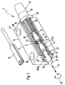
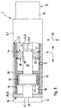
- FIG 1 is an embodiment of a shock absorber device 1 shown with a first embodiment a position detection device 2 is provided.
- the shock absorber device 1 has a housing 5 and one relative to Housing 5 movable actuating plunger 6, the housing 5 a first body 7 and the actuating plunger 6 a second Form body 8.
- the position detection device 2 serves at least to detect a relative position of the two bodies 7, 8. It understands yourself that the position detection device 2 not only as in present case shown in a shock absorber device 1 can be used, but always when one or several relative positions of two bodies 7, 8 are to be detected.
- the first body 7 from the housing and the second body 8 from the drive part movable relative to the housing be formed of a drive device, wherein as Drive device, a fluid-operated cylinder electric drive, a rotary drive or similar in question is coming.
- the exemplary shock absorber device 1 is usually used as a damping stop, so to speak, whereby any Moving part 9 shown schematically in broken lines in the final phase of its movement it is slowed down until it stops hits a stop, so that it has a defined end position occupies.
- it could be a moving one Part 9 around the drive part or associated driven parts an in particular piston rodless, fluid-operated drive device act, especially the output parts by means of a respective shock absorber device 1 in its end positions be dampened to cope with high material loads to avoid the drive device.
- a drive device For example, a so-called known per se Slot cylinder.
- the housing 5 of the shock absorber device 1 has a first one Housing part 12, which has a longitudinal recess 13, the the storage of the in the longitudinal direction 14 back and forth Actuating plunger 6 is used.
- the second body 8 in the longitudinal recess 13 of the first body 7 mounted movably relative to this in the longitudinal direction 14.
- the longitudinal recess 13 is in the preferred embodiment contoured like a cylinder, being coaxial to the longitudinal recess 13 a guide sleeve 17 is provided, the inside of which Has guide surface 18 on which the actuating plunger 6 is guided is present. It is understood that the actuating plunger 6 alternatively to the shown exemplary embodiments of the shock absorber device 1 also directly on the lateral surface of the longitudinal recess 13 could be performed or that in the longitudinal recess 13 a guide device is provided via which the actuating plunger 6 is slidably guided.
- the actuating plunger 6 has, for example, a guide section 21, whose outer diameter is essentially the inner diameter corresponds to the guide sleeve 17, the guide section 21 at least one guide ring on its outer circumference 22 carries, together with the guide surface facing him 18 of the guide sleeve 17 forms a sliding fit.
- the actuating plunger 6 is in a first in the present case Plunger element 23 and a second plunger element 24 divided, which are arranged axially one after the other.
- the first plunger element 23 has a in the longitudinal direction 14 from the Longitudinal recess 13 protruding actuating section 25, the cooperates with the moving part 9, the movement of which the shock absorber device 1 is to be braked in a damped manner.
- the longitudinal recess 13 is through a on the housing 5 in the area of the actuating section 25 of the actuating plunger 6
- Fastening element 28 is at least partially closed, that in the embodiment for attaching the guide sleeve 17 serves in the longitudinal recess 13.
- the fastener 28 can, as shown in Figure 1, like a nut be trained. It represents the preferred embodiment at the same time a stop body 29, which the associated End position of the to be braked by the shock absorber device 1 Moving part 9 defined, the moving part 9 in the end position on a stop surface 30 facing it Stop body 29 abuts. It is understood that the stop body 29 alternatively have any other shape could and also separately from the shock absorber device 1 could be arranged.
- the second plunger element 24 of the actuating plunger 6 is at least with its axially opposite the first plunger element 23 End section in a second housing part 32 of the housing 5 arranged longitudinally.
- the second housing part 32 has one for releasably connecting the two housing parts 32, 12 serving fastening part 33, which according to the example is provided with an external thread and in the actuating section 25 of the actuating plunger 6 opposite, with a correspondingly complementary internal thread end area 34 of the longitudinal recess 13 is screwed.
- Over a Lock nut 35 is the selected screw depth of the second Housing part 32 fixable.
- second housing part 32 alternatively to the preferred embodiment also on the outside of the first housing part 12 in an axial extension the longitudinal recess 13, for example by screwing be attached, the connection also by another any type can be made.
- the two plunger elements 23, 24 are expediently e.g. releasably connected to one another, for example by means of a Snap connection. It would also be conceivable for the two plunger elements 23, 24 in one piece.
- the second housing part 32 of the housing 5 and the second plunger element 24 of the actuating plunger 6 one jointly manageable unit, the actual one, so to speak Shock absorber 37 of the shock absorber device 1 represents.
- the advantage of this unit is that it can be replaced if necessary is. Due to the adjustable screw depth of the second housing part 32 in the longitudinal recess 13 of the first Housing part 12 can furthermore the maximum stroke of the actuating plunger 6 or the shock absorber 37 can be varied.
- a damping chamber filled with fluid in the one connected to the second plunger element 24 is arranged, which is not shown in the drawing is shown.
- the actuating plunger is in the rest position 6 of the shock absorber device 1 in its extended Position so that the operating portion 25 of the operating plunger 6 protrudes from the housing 5.
- a moving part 9 such as a Tool slide or other moving load, axially in Longitudinal direction 14 in the housing 5 or in the longitudinal recess 13 moves into it, the displacement body leads in the damping chamber also an axial movement, whereby he fluid must displace therein so that it does a job done.
- the kinetic energy of the moving Part 9 reduced so that it is braked.
- shock absorber device 1 In the embodiment of the shock absorber device shown in Figure 1 1 are on the first housing part 12 fasteners 38 provided for attaching the shock absorber device 1 serve on any holding part.
- fasteners 38 provided for attaching the shock absorber device 1 serve on any holding part.
- the shock absorber device 1 on a machine tool, on a fluidic or electrical drive device, attached to a fluid cylinder or the like.
- the position detection device 2 is used to do this, one or more relative positions of the two from the housing 5 and bodies 7, 8 formed by the actuating plunger 6 to capture.
- the exemplary shock absorber device 1 is the relative position of the two bodies 7, 8 to be detected from the fully inserted end position of the actuating plunger 6 formed with respect to the housing 5, as shown in the figures 3 and 5 is shown.
- the free outer end 41 is there essentially flush with the stop surface 30.
- the shock absorber device fulfills 1 two tasks simultaneously, namely damping or the braking of the moving part in the final phase of it Movement and the detection of the end position of the moving part the detection of the relative position of the two bodies 7, 8.
- the position detection device 2 has a fixed position on the first body 7 arranged sensor 44, which in the bodies 7, 8 to be detected relative position the magnetic field of a magnet 45, for example as a permanent magnet is executed, is actuated.
- the magnet 45 is in the first embodiment of the position detection device 2 according to Figures 1 to 3 with the actuating plunger 6 formed second body 8 coupled in motion, wherein it according to the example is fixedly attached to the second body 8.
- this is the magnet in the second embodiment according to Figures 4 and 5 stationary on the housing 5 formed first body 7 attached, so that it is stationary at the same time is arranged with respect to the sensor 44.
- the sensor 44 is on the outside of the housing 5 in a groove 46 in the longitudinal direction 14 displaceable and lockable so that it according to the relative position to be recorded by a Longitudinal displacement in the groove 46 is adjustable. It understands it turns out that in a further embodiment also several sensors 44 could be provided, e.g. by several relative positions of the two bodies 7, 8 to be detected. It can be useful here be to provide several grooves 46 on the housing 5 so that an unimpeded positioning of the sensors 44 in the longitudinal direction 14 is possible.
- the position detection device 2 also has a relative to the magnet 45 movable field influencing part 47.
- the field influencing part 47 is for influencing the magnetic field of the magnet 45 is provided and is in the embodiment made of magnetizable, for example ferromagnetic Material.
- the field influencing part is caused by the relative movement of the two bodies 7, 8 47 and the magnet 45 between a non-switching and a switching relative position, with the field influencing part 47 in the non-switching relative position thus arranged in the magnetic field of the magnet 45 is that the field strength of the magnetic field in the area of the sensor 44 below a switching value causing its actuation is.
- the field influencing part leaves 47 in the switching relative position in the area of the sensor 44 a field strength corresponding at least to the switching value to, so that actuation of the sensor 44 can take place.
- the field influencing part 47 is here of a length section the guide sleeve 17 formed so that it is stationary with respect of the first body 7 formed by the housing 5 and with respect of the sensor 44 provided on the housing 5 is.
- sleeve-like field influencing part 47 separately from the guide sleeve Train 17 and arrange on the housing 5 or as a component to execute the housing 5.
- the magnet 45 arranged on the actuating plunger 6 is preferably designed as a ring magnet and coaxial to the first plunger element 23 of the actuating plunger 6 arranged. He sits expediently on the opposite of the actuating section 25 End region 51 of the first plunger element 23.
- the sleeve-like field influencing part 47 is in such a way Arranged inside the housing 5 that it is the first plunger element 23 coaxially surrounds 52 in circumferential direction, whereby it is exemplary coaxial to the direction of movement of the relative movement is provided.
- the longitudinal extent of the field influencing part 47 is less than that of the first plunger element 23.
- the field strength of the magnetic field is in Area of the sensor 44 due to the good shielding of the field influencing part 47 in the non-switching relative position negligible, but it should be emphasized again that a reduction in the field strength below the switching value is sufficient.
- the field influencing part 47 is in the exemplary embodiment in the non-switching relative position at least partially between the sensor 44 and the magnet 45 are arranged.
- the field strength influence the magnetic field in the area of the sensor 44, however, other assignments are also conceivable.
- Possible influencing parameters are, for example, the direction of polarization of the magnet 45 (axial or radial), material and dimensioning of the field influencing part 47 or the distance between Magnet 45 and field influencing part 47 in the non-switching Relative position.
- the field influencing part 47 could in an alternative Embodiment of the position detection device 2 also a different one than that shown in the first embodiment have a sleeve-like shape.
- it could be one have plate-like shape curved in the circumferential direction 52 and be attached to the inside of the housing 5.
- the magnet 45 in the circumferential direction 52 partially surrounds and at least partially between the sensor 44 and the magnet 45 is arranged. Is a different than the cylindrical design of the housing provided in the example 5, the shape of the field influencing part 47 can be corresponding be adjusted.
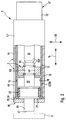
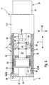
- the magnet 45 is also in Longitudinal direction 14 with respect to that of a length section 50 of the Guide sleeve 17 formed field influencing part 47 moved, until the relative position shown in FIG. 3 to be detected the two bodies 7, 8 are present.
- the magnet 45 is here completely from the sleeve-like field influencing part 47 in Moved longitudinal direction 14 so that its magnetic field in Radial direction 55 and on the field influencing part 47 opposite axial side 56 substantially unimpeded can spread.
- the magnet 45 is always with the second body 8 coupled in motion. It would be in another Design of the position detection device 2 also possible that the magnet 45 only in the transition between the non-switching and the switching relative position is motionally coupled to the second body 8. For example one could imagine that the second body 8 has a Type entrainment element that only in the switching area between non-switching and switching relative position with the Magnet 45 cooperates and thereby the relative movement between magnet 45 and the field influencing part 47.
- the sensitivity of the position detection device according to the invention 2 against scattering of the magnetic field is essential less than with position detection devices known since then, because in the non-switching relative position a relative strong concentration of the magnetic field in the field influencing part 47 takes place, so that scattering of the magnetic field, the can trigger an unwanted actuation of the sensor 44 avoided are. Only when magnet 45 and field influencing part 47 assume the switching relative position is in the range of Sensor 44 has a sufficiently strong magnetic field that actuation of the sensor 44 causes.
- the magnet 45 is in the switching relative position in the longitudinal direction 14 completely outside of the sleeve-shaped field influencing part 47 is arranged. It is understood that the field influencing part 47 the Magnet 45 also in the switching relative position in the circumferential direction 52 could still be partially surrounded, if in the area of Sensor 44 a field strength corresponding at least to the switching value the magnetic field is guaranteed so that its actuation he follows. This depends in particular on the specific design of the field influencing part 47 and the magnet 45.
- the second embodiment of the position detection device 2 is shown in Figures 4 and 5, with the reference numerals of the first embodiment in the second embodiment are used accordingly.
- the magnet 45 is as Ring magnet designed and arranged coaxially to the actuating plunger 6, now contrary to the first embodiment fixed to the housing and expediently on the inside of the housing 5 is attached.
- the magnet 45 is therefore fixed to the sensor 44 and to the second body 8 formed by the housing 5.
- the field influencing part 47 is of a length section of the Actuating plunger 6 is formed, which is the present Case is the second plunger element 24.
- the field influencing part 47 in one Embodiment not shown in detail coupled motion to train with the second body 8, it being constantly or just in the transition between the non-switching and the switching relative position with the second body 8 coupled in motion can be, so that a relative movement between Field influencing part 47 and that in the second embodiment with respect to the first body 7 stationary magnet 45 becomes.
- the field influencing part 47 coupled as a separate component with the actuating plunger 6 be or sit on it.
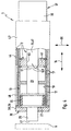
- Figure 4 is the non-switching relative position of the magnet 45 and field influencing part 47, the Shock absorber device 1 in the rest position with complete extended actuating plunger 6.
- the cylinder-like field influencing part 47 engages in this 4 non-switching relative position in the central Opening 60 of the magnet 45 designed as a ring magnet, whereby it projects completely through, for example.
- This Position is the magnetic field of the magnet 45 in the field influencing part 47 bundled, resulting in a weakening of the field strength at least radially on the field influencing part 47 opposite side of the magnet 45, so also in the area of the sensor 44.
- the field strength of the magnetic field can in this way in the area of the sensor 44 below the switching value being held.
- the magnet 45 is in the non-switching relative position in the second embodiment of the position detection device 2 entirely or partially between the field influencing part 47 and the sensor 44 arranged.
- the field influencing part could be in the area of the sensor 44 47 also only partially into the opening 60 of the magnet 45 protrude or this only in the longitudinal direction 14 be approximated if the field strength in the area of the Sensor 44 can be kept below the switching value.
- this is from the second plunger element 24 formed field influencing part in the switching relative position spaced in the longitudinal direction 14 to the magnet 45, so that it does not protrude into the opening 60 of the magnet 45.
- the magnetic field at least in the area of the sensor 44 with a field strength corresponding at least to the switching value build up or expand.
- the shock absorber device 1 forms together with the position detection device 2 in both embodiments Unit. This has the advantage that when reassembling the unit the sensor adjustment of the position detection device 2 is retained, so that readjustment of the sensor 44 can be omitted. Due to the specification of the radial distance between Magnet 45 and groove 46 through the first housing part 12 of the Housing 5, the position detection device 2 operates independently from the shock absorber used 37. The detection of a relative position and thus also the adjustment of the sensor 44 therefore regardless of the shock absorber used. Another change the shock absorber stroke does not require readjustment.
- Another advantage of the unit is that it is inexpensive Build up the fact that regarding the moving part 9 itself does not require immediate position detection. At the Use of the exemplary shock absorber device 1 takes over this at the same time both braking the moving part 9 as well as its position detection.
Landscapes
- Physics & Mathematics (AREA)
- Engineering & Computer Science (AREA)
- General Physics & Mathematics (AREA)
- Fluid Mechanics (AREA)
- Mechanical Engineering (AREA)
- General Engineering & Computer Science (AREA)
- Measurement Of Length, Angles, Or The Like Using Electric Or Magnetic Means (AREA)
- Vehicle Body Suspensions (AREA)
- Transmission And Conversion Of Sensor Element Output (AREA)
- Switches That Are Operated By Magnetic Or Electric Fields (AREA)
- Radar Systems Or Details Thereof (AREA)
Abstract
Description
- Figur 1
- eine Stoßdämpfereinrichtung mit einem ersten Ausführungsbeispiel der Positionserfassungsvorrichtung im Schrägbild in teilgeschnittener Darstellung,
- Figur 2
- die Stoßdämpfereinrichtung mit Positionserfassungsvorrichtung gemäß Figur 1 in schematischer, teilgeschnittener Seitenansicht, wobei sich das Feldbeeinflussungsteil und der Magnet der Positionserfassungsvorrichtung in der nichtschaltenden Relativposition befinden,
- Figur 3
- die Anordnung gemäß Figur 2, wobei sich das Feldbeeinflussungsteil und der Magnet der Positionserfassungsvorrichtung in der schaltenden Relativposition befinden,
- Figur 4
- die Stoßdämpfereinrichtung gemäß Figuren 1 bis 3 mit einem zweiten Ausführungsbeispiel der erfindungsgemäßen Positionserfassungsvorrichtung in einer schematischen, teilgeschnittenen Seitenansicht, wobei sich das Feldbeeinflussungsteil und der Magnet der Positionserfassungsvorrichtung in der nichtschaltenden Relativposition befinden und
- Figur 5
- die Anordnung gemäß Figur 4, wobei sich das Feldbeeinflussungsteil und der Magnet der Positionserfassungsvorrichtung in der schaltenden Relativposition befinden.
Claims (21)
- Positionserfassungsvorrichtung zur Erfassung wenigstens einer Relativposition zweier Köper (7, 9), mit wenigstens einem ortsfest bezüglich des einen Körpers (7) angeordneten Sensor (44), der bei in der zu erfassenden Relativposition befindlichen Körpern (7, 8) durch das Magnetfeld eines Magneten (45) betätigt wird, dadurch gekennzeichnet, daß mindestens ein Feldbeeinflussungsteil (47) vorgesehen ist, wobei das Feldbeeinflussungsteil (47) und der Magnet (45) relativ zueinander bewegbar sind und durch die Relativbewegung der beiden Körper (7, 8) zwischen einer nichtschaltenden und einer schaltenden Relativposition verlagerbar sind, wobei das Feldbeeinflussunsteil (47) in der nichtschaltenden Relativposition derart im Magnetfeld des Magneten (45) angeordnet ist, daß die Feldstärke des Magnetfeldes im Bereich des Sensors (44) unter einen dessen Betätigung hervorrufenden Schaltwert herabgesetzt ist, während es in der schaltenden Relativposition im Bereich des Sensors (44) eine mindestens dem Schaltwert entsprechende Feldstärke zuläßt.
- Positionserfassungsvorrichtung nach Anspruch 1, dadurch gekennzeichnet, daß das Feldbeeinflussungsteil (47) magnetisierbar ist und insbesondere aus ferromagnetischem Material besteht.
- Positionserfassungsvorrichtung nach Anspruch 1 oder 2, dadurch gekennzeichnet, daß das Feldbeeinflussungsteil (47) zumindest beim Übergang zwischen der nichtschaltenden und der schaltenden Relativposition mit einem der Körper (8) bewegungsgekoppelt ist.
- Positionserfassungsvorrichtung nach einem der Ansprüche 1 bis 3, dadurch gekennzeichnet, daß der Magnet (45) zumindest beim Übergang zwischen der schaltenden und der nichtschaltenden Relativposition mit einem der Körper (8) bewegungsgekoppelt ist.
- Positionserfassungsvorrichtung nach einem der Ansprüche 1 bis 4, dadurch gekennzeichnet, daß das Feldbeeinflussungsteil (47) und/oder der Magnet (45) ortsfest an einem der beiden Körper (7, 8) angeordnet sind bzw. ist.
- Positionserfassungsvorrichtung nach einem der Ansprüche 1 bis 5, dadurch gekennzeichnet, daß der Magnet (45) ortsfest bezüglich des Sensors (44) angeordnet ist.
- Positionserfassungsvorrichtung nach einem der Ansprüche 1 bis 5, dadurch gekennzeichnet, daß das Feldbeeinflussungsteil (47) ortsfest bezüglich des Sensors (44) angeordnet ist.
- Positionserfassungsvorrichtung nach einem der Ansprüche 1 bis 7, dadurch gekennzeichnet, daß das Feldbeeinflussungsteil (47) in der nichtschaltenden Relativposition zumindest teilweise zwischen dem Sensor (44) und dem Magneten (45) angeordnet ist.
- Positionserfassungsvorrichtung nach Anspruch 8, dadurch gekennzeichnet, daß das Feldbeeinflussungsteil (47) ein hülsenähnliches Abschirmteil darstellt, das den Magneten (45) in der nichtschaltenden Relativposition insbesondere koaxial zur Bewegungsrichtung der Relativbewegung umgibt.
- Positionserfassungsvorrichtung nach einem der Ansprüche 1 bis 7, dadurch gekennzeichnet, daß der Magnet (45) in der nichtschaltenden Relativposition ganz oder teilweise zwischen dem Feldbeeinflussungsteil (47) und dem Sensor (44) angeordnet ist.
- Positionserfassungsvorrichtung nach einem der Ansprüche 1 bis 10, dadurch gekennzeichnet, daß der Magnet (45) von einem Ringmagneten gebildet ist.
- Positionserfassungsvorrichtung nach Anspruch 11 in Verbindung mit Anspruch 10, dadurch gekennzeichnet, daß das Feldbeeinflussungsteil (47) in der nichtschaltenden Relativposition in die Öffnung (60) des Ringmagneten hineinragt.
- Positionserfassungsvorrichtung nach einem der Ansprüche 1 bis 12, dadurch gekennzeichnet, daß der eine Körper (7) vom Gehäuse und der andere Körper (8) vom relativ zum Gehäuse bewegbaren Antriebsteil einer Antriebseinrichtung, beispielsweise eines fluidbetätigten Arbeitszylinders, gebildet ist.
- Positionserfassungsvorrichtung nach Anspruch 13, dadurch gekennzeichnet, daß die wenigstens eine zu erfassende Relativposition der beiden Körper (7, 8) eine Endlage des Antriebsteils bezüglich des Gehäuses darstellt.
- Positionserfassungsvorrichtung nach einem der Ansprüche 1 bis 12, dadurch gekennzeichnet, daß der eine Körper vom Gehäuse (5) und der andere Körper von einem Betätigungsstößel (6) einer Stoßdämpfereinrichtung (1) gebildet ist.
- Positionserfassungsvorrichtung nach Anspruch 15, dadurch gekennzeichnet, daß der Betätigungsstößel (6) in zwei axial aufeinanderfolgend angeordnete Stößelelemente (23, 24) unterteilt ist, von denen das eine (24) das Feldbeeinflussungsteil (47) bildet.
- Positionserfassungsvorrichtung nach einem der Ansprüche 13 bis 16, dadurch gekennzeichnet, daß der Sensor (44) außen am Gehäuse (5) angeordnet ist.
- Positionserfassungsvorrichtung nach einem der Ansprüche 13 bis 17, dadurch gekennzeichnet, daß der Magnet (45) an der Innenseite des Gehäuses (5) befestigt ist.
- Positionserfassungsvorrichtung nach einem der Ansprüche 13 bis 17, dadurch gekennzeichnet, daß der Magnet (45) am Antriebsteil bzw. am Betätigungsstößel (6) befestigt ist.
- Positionserfassungsvorrichtung nach einem der Ansprüche 13 bis 19 in Verbindung mit Anspruch 11, dadurch gekennzeichnet, daß der Ringmagnet koaxial zum Antriebsteil bzw. zum Betätigungsstößel (6) angeordnet ist.
- Positionserfassungsvorrichtung nach einem der Ansprüche 13 bis 20, dadurch gekennzeichnet, daß das Feldbeeinflussungsteil (47) an der Innenseite des Gehäuses (5) der Antriebseinrichtung bzw. der Stoßdämpfereinrichtung (1) angeordnet ist.
Applications Claiming Priority (2)
| Application Number | Priority Date | Filing Date | Title |
|---|---|---|---|
| DE19805225A DE19805225C5 (de) | 1998-02-10 | 1998-02-10 | Positionserfassungsvorrichtung |
| DE19805225 | 1998-02-10 |
Publications (3)
| Publication Number | Publication Date |
|---|---|
| EP0936438A2 true EP0936438A2 (de) | 1999-08-18 |
| EP0936438A3 EP0936438A3 (de) | 1999-12-08 |
| EP0936438B1 EP0936438B1 (de) | 2004-08-04 |
Family
ID=7857170
Family Applications (1)
| Application Number | Title | Priority Date | Filing Date |
|---|---|---|---|
| EP98122279A Expired - Lifetime EP0936438B1 (de) | 1998-02-10 | 1998-11-24 | Positionserfassungsvorrichtung |
Country Status (3)
| Country | Link |
|---|---|
| EP (1) | EP0936438B1 (de) |
| AT (1) | ATE272827T1 (de) |
| DE (2) | DE19805225C5 (de) |
Cited By (1)
| Publication number | Priority date | Publication date | Assignee | Title |
|---|---|---|---|---|
| EP1241437A1 (de) * | 2001-02-23 | 2002-09-18 | Philips Corporate Intellectual Property GmbH | Magnetischer Positionssensor, Ventilstössel mit Magnethülse ( Ringscheiben ) |
Families Citing this family (4)
| Publication number | Priority date | Publication date | Assignee | Title |
|---|---|---|---|---|
| DE202005013065U1 (de) | 2005-08-18 | 2007-01-04 | Liebherr-Hausgeräte Ochsenhausen GmbH | Vorrichtung zur Positionserkennung |
| DE102009021081B4 (de) * | 2008-07-18 | 2017-07-06 | Asm Automation Sensorik Messtechnik Gmbh | Magnetischer Winkelsensor |
| EP2166312B2 (de) * | 2008-09-18 | 2020-01-15 | Sick Ag | Magnetischer oder induktiver Wegsensor |
| JP5382591B2 (ja) * | 2010-12-21 | 2014-01-08 | Smc株式会社 | 流体圧シリンダの位置検出装置 |
Family Cites Families (10)
| Publication number | Priority date | Publication date | Assignee | Title |
|---|---|---|---|---|
| DE1955597B2 (de) * | 1969-11-05 | 1971-12-09 | Hoesch AG, 4600 Dortmund, Elf GuIl, Karl Heinz, 5040 Bruhl, Marke, Bernd Dieter, 5950 Finnentrop | Elektrisch gesteuerte Niveauregelanlage fur Fahrzeuge, insbesondere Kraftfahrzeuge |
| DE3442879C2 (de) * | 1984-11-24 | 1994-09-01 | Wabco Vermoegensverwaltung | Einrichtung zum Erfassen der relativen Position von zwei relativ zueinander bewegbaren Teilen |
| KR900004780B1 (ko) * | 1985-09-13 | 1990-07-05 | 후지쓰 가부시끼가이샤 | 자기(磁氣) 센서를 사용한 위치 검출장치 |
| JPS63122902A (ja) * | 1986-11-13 | 1988-05-26 | Ckd Controls Ltd | 移動体の位置確認装置 |
| DE8901770U1 (de) * | 1989-02-15 | 1990-07-26 | Schaltbau GmbH, 8000 München | Stellantrieb |
| DE9010114U1 (de) * | 1990-07-03 | 1990-09-06 | Festo KG, 7300 Esslingen | Arbeitszylinder |
| JPH04160315A (ja) * | 1990-10-24 | 1992-06-03 | Fujitsu Ltd | リニア型位置センサ |
| US5257014A (en) * | 1991-10-31 | 1993-10-26 | Caterpillar Inc. | Actuator detection method and apparatus for an electromechanical actuator |
| DE4333800A1 (de) * | 1993-10-04 | 1995-04-06 | Deutsche Automobilgesellsch | Vorrichtung zur Drehwinkeldetektierung |
| US5621317A (en) * | 1994-12-12 | 1997-04-15 | Ford Motor Company | Position sensor with a magnetic proximity switch mechanism |
-
1998
- 1998-02-10 DE DE19805225A patent/DE19805225C5/de not_active Expired - Fee Related
- 1998-11-24 EP EP98122279A patent/EP0936438B1/de not_active Expired - Lifetime
- 1998-11-24 AT AT98122279T patent/ATE272827T1/de not_active IP Right Cessation
- 1998-11-24 DE DE59811755T patent/DE59811755D1/de not_active Expired - Lifetime
Cited By (1)
| Publication number | Priority date | Publication date | Assignee | Title |
|---|---|---|---|---|
| EP1241437A1 (de) * | 2001-02-23 | 2002-09-18 | Philips Corporate Intellectual Property GmbH | Magnetischer Positionssensor, Ventilstössel mit Magnethülse ( Ringscheiben ) |
Also Published As
| Publication number | Publication date |
|---|---|
| EP0936438A3 (de) | 1999-12-08 |
| DE19805225C5 (de) | 2005-02-03 |
| DE19805225C2 (de) | 2000-11-23 |
| EP0936438B1 (de) | 2004-08-04 |
| ATE272827T1 (de) | 2004-08-15 |
| DE19805225A1 (de) | 1999-08-12 |
| DE59811755D1 (de) | 2004-09-09 |
Similar Documents
| Publication | Publication Date | Title |
|---|---|---|
| DE3525029C2 (de) | Kolben-Zylinder-Anordnung | |
| DE3734547C2 (de) | ||
| EP0930504B1 (de) | Deckelgreifvorrichtung | |
| DE3535704A1 (de) | Kolben-zylinder-anordnung | |
| DE102019120427B4 (de) | Bohrungsspanner mit Rückstelleinrichtung | |
| EP0649004A2 (de) | Positionserfassungsvorrichtung an einem Linearantrieb | |
| DE4108158C2 (de) | Linear-Antriebsvorrichtung | |
| DE8505017U1 (de) | Hydraulischer oder pneumatischer arbeitszylinder | |
| DE102016209824A1 (de) | Dämpfer | |
| EP0936438B1 (de) | Positionserfassungsvorrichtung | |
| DE3103819A1 (de) | Instrument zur messung von innendurchmessern | |
| DE3537124C2 (de) | Arbeitszylinder | |
| DE102011118519B4 (de) | Fluidbetätigter Linearantrieb | |
| DE202015104756U1 (de) | Schalteinrichtung zum Schalten eines Mehrkupplungsgetriebes | |
| DE10116634A1 (de) | Führungseinrichtung und Anfahranbausatz | |
| DE8909282U1 (de) | Pneumatisch betriebene Vorrichtung zur plastischen Verformung, insbesondere zum Schlagstempeln | |
| EP1245345A1 (de) | Fluidbetätigter Greifer | |
| EP1069410A1 (de) | Vorrichtung zur lösbaren Verankerung eines Sensors | |
| DE8807514U1 (de) | Anschlagvorrichtung | |
| DE3502615A1 (de) | Anschlaganordnung fuer eine druckmittelbetaetigte kolben-zylinder-einheit | |
| DE102006016611A1 (de) | Sicherheitsbremse | |
| DE19649718C1 (de) | Linearantrieb | |
| DE202010009543U1 (de) | Positionsvorgabeeinrichtung und damit ausgestattete Antriebsvorrichtung | |
| EP0812991B1 (de) | Druckmittelbetätigbarer Arbeitszylinder | |
| DE102004011625B4 (de) | Linearantrieb |
Legal Events
| Date | Code | Title | Description |
|---|---|---|---|
| PUAI | Public reference made under article 153(3) epc to a published international application that has entered the european phase |
Free format text: ORIGINAL CODE: 0009012 |
|
| AK | Designated contracting states |
Kind code of ref document: A2 Designated state(s): AT CH DE FR GB IT LI |
|
| AX | Request for extension of the european patent |
Free format text: AL;LT;LV;MK;RO;SI |
|
| PUAL | Search report despatched |
Free format text: ORIGINAL CODE: 0009013 |
|
| AK | Designated contracting states |
Kind code of ref document: A3 Designated state(s): AT BE CH CY DE DK ES FI FR GB GR IE IT LI LU MC NL PT SE |
|
| AX | Request for extension of the european patent |
Free format text: AL;LT;LV;MK;RO;SI |
|
| 17P | Request for examination filed |
Effective date: 19991124 |
|
| AKX | Designation fees paid |
Free format text: AT CH DE FR GB IT LI |
|
| 17Q | First examination report despatched |
Effective date: 20030415 |
|
| GRAP | Despatch of communication of intention to grant a patent |
Free format text: ORIGINAL CODE: EPIDOSNIGR1 |
|
| GRAS | Grant fee paid |
Free format text: ORIGINAL CODE: EPIDOSNIGR3 |
|
| GRAA | (expected) grant |
Free format text: ORIGINAL CODE: 0009210 |
|
| AK | Designated contracting states |
Kind code of ref document: B1 Designated state(s): AT CH DE FR GB IT LI |
|
| REG | Reference to a national code |
Ref country code: GB Ref legal event code: FG4D Free format text: NOT ENGLISH |
|
| REG | Reference to a national code |
Ref country code: CH Ref legal event code: NV Representative=s name: TROESCH SCHEIDEGGER WERNER AG Ref country code: CH Ref legal event code: EP |
|
| REF | Corresponds to: |
Ref document number: 59811755 Country of ref document: DE Date of ref document: 20040909 Kind code of ref document: P |
|
| GBT | Gb: translation of ep patent filed (gb section 77(6)(a)/1977) | ||
| PLBE | No opposition filed within time limit |
Free format text: ORIGINAL CODE: 0009261 |
|
| STAA | Information on the status of an ep patent application or granted ep patent |
Free format text: STATUS: NO OPPOSITION FILED WITHIN TIME LIMIT |
|
| ET | Fr: translation filed | ||
| 26N | No opposition filed |
Effective date: 20050506 |
|
| PGFP | Annual fee paid to national office [announced via postgrant information from national office to epo] |
Ref country code: AT Payment date: 20051121 Year of fee payment: 8 |
|
| PG25 | Lapsed in a contracting state [announced via postgrant information from national office to epo] |
Ref country code: AT Free format text: LAPSE BECAUSE OF NON-PAYMENT OF DUE FEES Effective date: 20061124 |
|
| PGFP | Annual fee paid to national office [announced via postgrant information from national office to epo] |
Ref country code: GB Payment date: 20101105 Year of fee payment: 13 Ref country code: IT Payment date: 20101123 Year of fee payment: 13 |
|
| PGFP | Annual fee paid to national office [announced via postgrant information from national office to epo] |
Ref country code: FR Payment date: 20111125 Year of fee payment: 14 Ref country code: CH Payment date: 20111129 Year of fee payment: 14 |
|
| PGFP | Annual fee paid to national office [announced via postgrant information from national office to epo] |
Ref country code: DE Payment date: 20121012 Year of fee payment: 15 |
|
| REG | Reference to a national code |
Ref country code: CH Ref legal event code: PL |
|
| GBPC | Gb: european patent ceased through non-payment of renewal fee |
Effective date: 20121124 |
|
| PG25 | Lapsed in a contracting state [announced via postgrant information from national office to epo] |
Ref country code: LI Free format text: LAPSE BECAUSE OF NON-PAYMENT OF DUE FEES Effective date: 20121130 Ref country code: CH Free format text: LAPSE BECAUSE OF NON-PAYMENT OF DUE FEES Effective date: 20121130 |
|
| REG | Reference to a national code |
Ref country code: FR Ref legal event code: ST Effective date: 20130731 |
|
| PG25 | Lapsed in a contracting state [announced via postgrant information from national office to epo] |
Ref country code: IT Free format text: LAPSE BECAUSE OF NON-PAYMENT OF DUE FEES Effective date: 20121124 |
|
| PG25 | Lapsed in a contracting state [announced via postgrant information from national office to epo] |
Ref country code: GB Free format text: LAPSE BECAUSE OF NON-PAYMENT OF DUE FEES Effective date: 20121124 Ref country code: FR Free format text: LAPSE BECAUSE OF NON-PAYMENT OF DUE FEES Effective date: 20121130 |
|
| REG | Reference to a national code |
Ref country code: DE Ref legal event code: R119 Ref document number: 59811755 Country of ref document: DE |
|
| PG25 | Lapsed in a contracting state [announced via postgrant information from national office to epo] |
Ref country code: DE Free format text: LAPSE BECAUSE OF NON-PAYMENT OF DUE FEES Effective date: 20140603 |
|
| REG | Reference to a national code |
Ref country code: DE Ref legal event code: R119 Ref document number: 59811755 Country of ref document: DE Effective date: 20140603 |