EP0936636A2 - Electromagnet - Google Patents
Electromagnet Download PDFInfo
- Publication number
- EP0936636A2 EP0936636A2 EP98124681A EP98124681A EP0936636A2 EP 0936636 A2 EP0936636 A2 EP 0936636A2 EP 98124681 A EP98124681 A EP 98124681A EP 98124681 A EP98124681 A EP 98124681A EP 0936636 A2 EP0936636 A2 EP 0936636A2
- Authority
- EP
- European Patent Office
- Prior art keywords
- coil
- magnet
- materials
- field strength
- diffusion
- Prior art date
- Legal status (The legal status is an assumption and is not a legal conclusion. Google has not performed a legal analysis and makes no representation as to the accuracy of the status listed.)
- Withdrawn
Links
Images

Classifications
-
- H—ELECTRICITY
- H01—ELECTRIC ELEMENTS
- H01F—MAGNETS; INDUCTANCES; TRANSFORMERS; SELECTION OF MATERIALS FOR THEIR MAGNETIC PROPERTIES
- H01F3/00—Cores, Yokes, or armatures
- H01F3/10—Composite arrangements of magnetic circuits
-
- F—MECHANICAL ENGINEERING; LIGHTING; HEATING; WEAPONS; BLASTING
- F01—MACHINES OR ENGINES IN GENERAL; ENGINE PLANTS IN GENERAL; STEAM ENGINES
- F01L—CYCLICALLY OPERATING VALVES FOR MACHINES OR ENGINES
- F01L9/00—Valve-gear or valve arrangements actuated non-mechanically
- F01L9/20—Valve-gear or valve arrangements actuated non-mechanically by electric means
-
- H—ELECTRICITY
- H01—ELECTRIC ELEMENTS
- H01F—MAGNETS; INDUCTANCES; TRANSFORMERS; SELECTION OF MATERIALS FOR THEIR MAGNETIC PROPERTIES
- H01F7/00—Magnets
- H01F7/06—Electromagnets; Actuators including electromagnets
- H01F7/08—Electromagnets; Actuators including electromagnets with armatures
- H01F7/081—Magnetic constructions
-
- H—ELECTRICITY
- H01—ELECTRIC ELEMENTS
- H01F—MAGNETS; INDUCTANCES; TRANSFORMERS; SELECTION OF MATERIALS FOR THEIR MAGNETIC PROPERTIES
- H01F3/00—Cores, Yokes, or armatures
- H01F3/10—Composite arrangements of magnetic circuits
- H01F2003/106—Magnetic circuits using combinations of different magnetic materials
Definitions
- the invention relates to an electromagnet according to the preamble of claim 1.
- electromagnets with a coil and a ferromagnetic core are generally used.
- the core is located in and / or surrounds the coil. If a current is passed through the coil, a magnetic field with the field strength H builds up around the coil in accordance with the law on flooding. Under the force of the magnetic field, the magnetic dipoles present in the core material orient themselves in the field direction and thus increase the magnetic flux density or induction in comparison to an air coil from B 0 to B. The resulting flux density is therefore dependent on the field strength H.
- Electromagnetic actuators gas exchange valves usually have two solenoids, an opening magnet and a closing magnet with one coil and one core, between their pole faces an armature arranged coaxially to a valve axis is.
- the armature acts on a valve stem via an armature tappet of the gas exchange valve.
- a preloaded spring mechanism acts on the mass oscillator on the anchor.
- Compression springs namely an upper and a lower Valve spring.
- the upper valve spring loads in the opening direction and the lower valve spring in the closing direction of the gas exchange valve. If the magnet is not excited, the armature is replaced by the Valve springs in an equilibrium position between the magnets held.
- the actuator is activated at start, either the Closing magnet or the opening magnet temporarily overexcited or the anchor with a start-up routine with its resonance frequency stimulated to be attracted to out of balance become.
- the armature on the pole face of the energized closing magnet and is held by this.
- the closing magnet clamps the in Valve spring acting in the opening direction further forward.
- the closing magnet is switched off and the opening magnet is switched on.
- the in the opening direction Acting valve spring accelerates the armature over the Equilibrium position, so that this from the opening magnet is attracted.
- the anchor hits the pole face of the Opening magnet and is held by this.
- the flight time of the anchor between the opening magnet and the Closing magnet is very short and is usually not enough that the Core of the catching magnet completely from the magnetic field of the Coil is interspersed after a voltage is applied to it has been.
- the catching magnet must be activated before the anchor detaches from the holding magnet. This leads to unnecessary energy expenditure.
- the mostly relatively sluggishly appealing Magnet does not react to abrupt disturbances become.
- the coil core consists of a composite body, that of at least two mechanically clamped materials exists, at least one of which is ferromagnetic and in Longitudinal axis anisotropic, soft magnetic Possesses properties.
- the composite body becomes a soft magnetic Body associated with a lower coercive force than the ferromagnetic part of the composite body and is sufficiently magnetostatically coupled to it.
- the mechanical stresses in the composite body result in Longitudinal direction of the coil core is a magnetic preferred direction. If an external magnetic field acts on the coil core, it changes the direction of magnetization in the composite body more or less erratic when a certain field strength is exceeded or is fallen below, which can generate pulses.
- the object of the invention is an electromagnet to develop the greatest attraction in the shortest possible time or holding force generated to thereby in particular an actuator for actuating a gas exchange valve To be able to control valve movement better.
- the task is solved according to the invention by the features of claim 1, while advantageous refinements and developments of Invention can be found in the dependent claims.
- the permeability number ⁇ r (H) depends on the field strength H, and in fact it drops at a specific field strength H S.
- the magnetic flux density B characterized rises in a first region with the field strength H almost linearly and aims at a field strength H S, in a second non-linear region, a saturation flux density B s to.
- the invention is based on the knowledge that at a field strength H S , in which one is in the area of the saturation flux density B S , less eddy currents occur in the core material and the diffusion rate v D of the magnetic field into the core material is many times greater than in one Field strength H at which you are still in the linear range of B. The following applies to the diffusion rate v D : V D ⁇ t ⁇
- Velocity values higher by a factor of 200 to 300 are achieved (see Feinwerktechnik & Messtechnik 90 (1982) 5, B. Aldefeld: Felddiffusion in Elektromagneten, p. 222 ff.). Furthermore, the permeability ⁇ in the case of core materials with a lower saturation flux density B S is smaller overall and thus the diffusion rate is greater.
- the material closer to the coil in the diffusion direction has a smaller saturation flux density B S , which is achieved at a smaller field strength H S than the material which is further away from the coil. If the electromagnet is activated or a voltage is applied to the coil, a voltage arises through self-induction in the coil, which delays the current increase I and thus the increase in the magnetic field strength H.
- the coil core according to the invention already achieves the saturation flux density B S of the materials closer to the coil in the diffusion direction in the rise phase of the magnetic field strength H, ie with a small magnetic field strength H S , so that a low permeability ⁇ and a high diffusion speed v D.
- the materials in the diffusion direction are preferably matched to the course of the magnetic field strength in such a way that a small permeability ⁇ and a high diffusion speed v D occurs.
- electromagnets according to the invention in an actuator, with the one as described above, a gas exchange valve Internal combustion engine is actuated via an anchor.
- the electromagnet can be activated more quickly become, for example, only after the anchor of a opposite, previously holding magnets which saves energy.
- the shorter Response time of the electromagnet the valve movement more precisely can be regulated, in particular, may occur Faults are reacted to more quickly.
- a catching electromagnet for example the opening magnet, acts as early as possible on the armature with as large a force as possible after it has detached itself from a previously holding electromagnet, the closing magnet, it is known as a so-called characteristic-influenced electromagnet "(KLB magnet).
- the coil core of the KLB magnet preferably has a step in the area of the coil in the direction of the correspondingly shaped armature, as a result of which the armature enters the magnetic field of the catching KLB magnet earlier.
- the flight time of the armature The magnetic field of the capturing magnet is shorter than that of a flat coil core or flat pole face, so that the KLB magnet has built up as strong a magnetic field as possible after the short flight time and can exert its special effect with conventional electromagnets activated particularly early, ie before the armature detaches from the holding electromagnet, which consumes unnecessary energy and there is a risk that the armature will separate more easily from the pole face of the holding magnet if there are additional influences.
- Magnets according to the invention Execute electromagnets with a quick power build-up. Energy is saved and the risk of the anchor unintentionally loosening too early is reduced. It is also possible to combine further constructions known to the person skilled in the art to increase the force or acceleration of the force build-up with the electromagnet according to the invention, such as, for example, with a coil core constructed from mutually insulated sheets, as described above.
- the electromagnet according to the invention can be used in addition to Actuators for gas exchange valves, preferably in all areas of application be used where possible faster strength building is required.
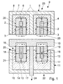
- Fig. 1 shows a section of an actuator 9, the one Opening magnet 22 and a closing magnet 23.
- the Electromagnets 22, 23 each have a coil 4, 12 that is surrounded by a coil core 5, 11. Will be on one of the coils 4, 12 a voltage is applied, the current I rises through the Self-induction delayed on (Fig. 2).
- Fig. 2 Around the coil 4, 12 creates a magnetic field 20, 21, the field strength H corresponding the current intensity I rises with a delay (FIG. 3).
- the Magnetic field 20, 21 spreads from the coil 4, 12 in the coil core 5, 11, i.e. be in the coil core 5, 11 existing magnetic dipoles aligned in the field direction what is also referred to as diffusion.
- the coil cores 5, 11 have different ferromagnetic materials 6, 7, 8, 13, 14, 15 in the diffusion direction 1, 2, 3, 17, 18, 19. Ferromagnetic materials have a permeability number ⁇ r that depends on the field strength H, and this rises first to a maximum value and then falls again (FIG. 4).
- ⁇ r ⁇ O H results from the fact that the flux density B of a certain field strength H S, in which the relative permeability ⁇ r falls, at a saturation flux density B approaches S (Fig. 5 and 6).
- the flux density B is plotted against the field strength H for two different material combinations, in FIG. 5 for the closing magnet 23 and in FIG. 6 for the opening magnet 22.
- the materials 6, 7, 8 in the diffusion direction 1, 2, 3 each have a greater increase in the flux density B in the case of small field strengths H, while the materials 13, 14, 15 of the opening magnet 22 have in the diffusion direction 17, 18, 19 with small field strengths H a smaller increase in the flux density B, a combination between the materials 13, 14, 15 of the opening magnet 22 and that of the closing magnet 23 being possible.
- a combination of materials in the direction of diffusion 1, 2, 3, 17, 18, 19 could be, for example, mild steel, structural steel and Armco iron.
- the diffusion has a velocity v D , which depends on the permeability ⁇ and thus on the permeability number ⁇ r , namely: V D ⁇ t ⁇
- the diffusion rate v D is very large with a small permeability number and thus in the saturation range of a material. If the field strength H increases according to FIG. 3, the field strength H S6 or H S13 of materials 6 or 13 is reached early, still in the rise phase of H, and then that of materials 7, 8 or 14, 15. Already in In the rise phase of H, particularly high diffusion velocities V D are achieved and thus a particularly rapid build-up of force.
- the opening magnet 22 is for this preferably as a so-called characteristic-influenced magnet (KLB magnet), i.e. the opening magnet 22 has a stepped pole face 25 or is corresponding in the direction 16 of the molded anchor 10 executed stepped. This will be preferred achieved in that the coil 12 of core material 13 surrounded offset in the direction 16 of the armature 10 is.
- the opening magnet 22 thus acts with its magnetic field 21 earlier on from the closing magnet 23 in the opening direction 24 moving anchor 10.
- the flight time of anchor 10 from Closing magnet 23 into the effective range of the opening magnet 22 is therefore particularly short.
- the magnetic field 21 must can be built up quickly, so that a construction according to the invention of the coil core 11 with different materials 13, 14, 15 is particularly advantageous.
Landscapes
- Engineering & Computer Science (AREA)
- Physics & Mathematics (AREA)
- Electromagnetism (AREA)
- Power Engineering (AREA)
- Mechanical Engineering (AREA)
- General Engineering & Computer Science (AREA)
- Chemical & Material Sciences (AREA)
- Composite Materials (AREA)
- Electromagnets (AREA)
- Valve Device For Special Equipments (AREA)
- Particle Accelerators (AREA)
Abstract
Description
Die Erfindung betrifft einen Elektromagneten nach dem Oberbegriff des Patentanspruchs 1.The invention relates to an electromagnet according to the preamble of claim 1.
Um möglichst starke elektromagnetische Felder zu erzeugen,
werden in der Regel Elektromagnete mit einer Spule und einem
ferromagnetischen Kern verwendet. Der Kern befindet sich in der
Spule und/oder umgibt diese. Wird ein Strom durch die Spule
geleitet, baut sich gemäß dem Durchflutungsgesetz um die Spule
ein Magnetfeld mit der Feldstärke H auf. Unter der Kraftwirkung
des Magnetfelds orientieren sich die im Kernmaterial vorhandenen
magnetischen Dipole in Feldrichtung und erhöhen so die
magnetische Flußdichte bzw. Induktion im Vergleich zu einer
Luftspule von B0 auf B. Die resultierende Flußdichte ist damit
von der Feldstärke H abhängig. Der funktionale Zusammenhang
wird durch die nichtlineare Magnetisierungskurve
Um eine kurze Ansprechzeit bei einem Elektromagneten zu erreichen, sollte das elektromagnetische Feld schnell aufgebaut und auch wieder abgebaut werden und trotz geringen Abmessungen des Elektromagneten eine große Endkraft ergeben. Dies ist insbesondere bei sehr dynamischen Systemen wichtig, wie z.B. bei Aktuatoren zur Betätigung von Gaswechselventilen von Brennkraftmaschinen. Elektromagnetische Aktuatoren zur Betätigung von Gaswechselventilen besitzen in der Regel zwei Schaltmagnete, einen Öffnungsmagneten und einen Schließmagneten mit jeweils einer Spule und einem Kern, zwischen deren Polflächen ein Anker koaxial zu einer Ventilachse verschiebbar angeordnet ist. Der Anker wirkt über einen Ankerstößel auf einen Ventilschaft des Gaswechselventils. Bei Aktuatoren nach dem Prinzip des Massenschwingers wirkt ein vorgespannter Federmechanismus auf den Anker. Als Federmechanismus dienen meist zwei vorgespannte Druckfedern, und zwar eine obere und eine untere Ventilfeder. Die obere Ventilfeder belastet in Öffnungsrichtung und die untere Ventilfeder in Schließrichtung des Gaswechselventils. Bei nicht erregten Magneten wird der Anker durch die Ventilfedern in einer Gleichgewichtslage zwischen den Magneten gehalten.To achieve a short response time with an electromagnet, the electromagnetic field should build up quickly and can also be dismantled and despite the small dimensions of the Electromagnets have a large final force. This is particularly so important for very dynamic systems, e.g. at Actuators for actuating gas exchange valves of internal combustion engines. Electromagnetic actuators gas exchange valves usually have two solenoids, an opening magnet and a closing magnet with one coil and one core, between their pole faces an armature arranged coaxially to a valve axis is. The armature acts on a valve stem via an armature tappet of the gas exchange valve. For actuators based on the principle a preloaded spring mechanism acts on the mass oscillator on the anchor. Usually two preloaded spring mechanisms are used Compression springs, namely an upper and a lower Valve spring. The upper valve spring loads in the opening direction and the lower valve spring in the closing direction of the gas exchange valve. If the magnet is not excited, the armature is replaced by the Valve springs in an equilibrium position between the magnets held.
Wird der Aktuator beim Start aktiviert, wird entweder der Schließmagnet oder der Öffnungsmagnet kurzzeitig übererregt oder der Anker mit einer Anschwingroutine mit seiner Resonanzfrequenz angeregt, um aus der Gleichgewichtslage angezogen zu werden. In geschlossener Stellung des Gaswechselventils liegt der Anker an der Polfläche des erregten Schließmagneten an und wird von diesem gehalten. Der Schließmagnet spannt die in Öffnungsrichtung wirkende Ventilfeder weiter vor. Um das Gaswechselventil zu öffnen, wird der Schließmagnet ausgeschaltet und der Öffnungsmagnet eingeschaltet. Die in Öffnungsrichtung wirkende Ventilfeder beschleunigt den Anker über die Gleichgewichtslage hinaus, so daß dieser von dem Öffnungsmagneten angezogen wird. Der Anker schlägt an die Polfläche des Öffnungsmagneten an und wird von dieser festgehalten. Um das Gaswechselventil wieder zu schließen, wird der Öffnungsmagnet ausgeschaltet und der Schließmagnet eingeschaltet. Die in Schließrichtung wirkende Ventilfeder beschleunigt den Anker über die Gleichgewichtslage hinaus zum Schließmagneten. Der Anker wird vom Schließmagneten angezogen, schlägt auf die Polfläche des Schließmagneten auf und wird von diesem festgehalten. If the actuator is activated at start, either the Closing magnet or the opening magnet temporarily overexcited or the anchor with a start-up routine with its resonance frequency stimulated to be attracted to out of balance become. In the closed position of the gas exchange valve the armature on the pole face of the energized closing magnet and is held by this. The closing magnet clamps the in Valve spring acting in the opening direction further forward. To do that To open the gas exchange valve, the closing magnet is switched off and the opening magnet is switched on. The in the opening direction Acting valve spring accelerates the armature over the Equilibrium position, so that this from the opening magnet is attracted. The anchor hits the pole face of the Opening magnet and is held by this. To do that To close the gas exchange valve again, the opening magnet switched off and the closing magnet switched on. In the Valve spring acting in the closing direction accelerates the armature beyond the equilibrium position to the closing magnet. Of the Anchor is attracted by the closing magnet, strikes the Pole surface of the closing magnet and is held by this.
Die Flugzeit des Ankers zwischen dem Öffnungsmagneten und dem Schließmagneten ist sehr kurz und reicht meist nicht, daß der Kern des fangenden Magneten vollständig vom Magnetfeld der Spule durchsetzt ist, nachdem an diese eine Spannung angelegt wurde. Um zu erreichen, daß der Kern vom Magnetfeld vollständig durchsetzt bzw. der Magnet eine ausreichende Anziehungskraft erreicht hat, sobald der Anker in dessen Wirkungsbereich kommt, muß der fangende Magnet aktiviert werden bevor sich der Anker vom haltenden Magneten löst. Dies führt zu unnötigem Energieaufwand. Ferner kann mit den meist relativ träg ansprechenden Magneten nicht auf abrupt auftretende Störgrößen reagiert werden.The flight time of the anchor between the opening magnet and the Closing magnet is very short and is usually not enough that the Core of the catching magnet completely from the magnetic field of the Coil is interspersed after a voltage is applied to it has been. To ensure that the core is completely free of the magnetic field penetrates or the magnet has sufficient attraction has reached as soon as the anchor comes into its area of effect, the catching magnet must be activated before the anchor detaches from the holding magnet. This leads to unnecessary energy expenditure. Furthermore, with the mostly relatively sluggishly appealing Magnet does not react to abrupt disturbances become.
Es ist bekannt, Eisenkerne aus gegeneinander isolierten, dünnen Blechen aufzubauen, deren Berührungsflächen quer zu den elektrischen Feldlinien liegen, d.h. senkrecht zur Wicklung der Spule (vgl. H. Linse, Elektrotechnik für Maschinenbauer, 8., überarbeitete Auflage, Teubner 1987, S. 66 ff). Dadurch treten in den einzelnen Blechen nur kleine Spannungen und damit kleine Wirbelströme auf.It is known to make iron cores from thin insulated from each other Build up sheets with their contact surfaces across the electrical Field lines lie, i.e. perpendicular to the winding of the Coil (see H. Linse, electrical engineering for mechanical engineers, 8th, revised edition, Teubner 1987, p. 66 ff). Step through it only small tensions in the individual sheets and thus small Eddy currents.
Ferner ist aus der DE 37 29 418 A1 bekannt, einen Spulenkern in Längsrichtung nebeneinander aus verschiedenen Materialien herzustellen. Der Spulenkern besteht aus einem Verbundkörper, der aus zumindest zwei mechanisch verspannten Materialien besteht, von denen mindestens eines ferromagnetisch ist und in Richtung der Längsachse anisotropische, weichmagnetische Eigenschaften besitzt. Dem Verbundkörper wird ein weichmagnetischer Körper zugeordnet, welcher eine niedrigere Koerzitivfeldstärke als der ferromagnetische Teil des Verbundkörpers aufweist und mit diesem magnetostatisch ausreichend gekoppelt ist. Durch die mechanischen Spannungen im Verbundkörper entsteht in Längsrichtung des Spulenkerns eine magnetische Vorzugsrichtung. Wirkt auf den Spulenkern ein äußeres Magnetfeld, ändert sich die Magnetisierungsrichtung im Verbundkörper mehr oder weniger sprunghaft, wenn eine bestimmte Feldstärke überschritten oder unterschritten wird, wodurch Impulse erzeugt werden können. It is also known from DE 37 29 418 A1 to have a coil core in Longitudinal side by side from different materials to manufacture. The coil core consists of a composite body, that of at least two mechanically clamped materials exists, at least one of which is ferromagnetic and in Longitudinal axis anisotropic, soft magnetic Possesses properties. The composite body becomes a soft magnetic Body associated with a lower coercive force than the ferromagnetic part of the composite body and is sufficiently magnetostatically coupled to it. The mechanical stresses in the composite body result in Longitudinal direction of the coil core is a magnetic preferred direction. If an external magnetic field acts on the coil core, it changes the direction of magnetization in the composite body more or less erratic when a certain field strength is exceeded or is fallen below, which can generate pulses.
Durch den zusätzlichen weichmagnetischen Körper können in einem Hysteresiszyklus zwei Impulse erzeugt werden. Ferner können auch kurze Spulenkerne verwendet werden.Due to the additional soft magnetic body you can in one Hysteresis cycle two pulses are generated. Can also also short coil cores can be used.
Die Aufgabe der Erfindung besteht darin, einen Elektromagneten zu entwickeln, der möglichst in kurzer Zeit eine große Anziehungskraft bzw. Haltekraft erzeugt, um dadurch insbesondere bei einem Aktuator zur Betätigung eines Gaswechselventils die Ventilbewegung besser steuern zu können. Die Aufgabe wird erfindungsgemäß durch die Merkmale des Anspruchs 1 gelöst, während vorteilhafte Ausgestaltungen und Weiterbildungen der Erfindung den Unteransprüchen entnommen werden können.The object of the invention is an electromagnet to develop the greatest attraction in the shortest possible time or holding force generated to thereby in particular an actuator for actuating a gas exchange valve To be able to control valve movement better. The task is solved according to the invention by the features of claim 1, while advantageous refinements and developments of Invention can be found in the dependent claims.
Für die magnetische Flußdichte B gilt:
Bei ferromagnetischen Materialien ist die Permeabilitätszahl
µr(H) von der Feldstärke H abhängig, und zwar fällt sie bei
einer bestimmten Feldstärke HS ab. Die magnetische Flußdichte B
steigt dadurch in einem ersten Bereich mit der Feldstärke H
nahezu linear an und strebt ab einer Feldstärke HS in einem
zweiten nicht linearen Bereich eine Sättigungsflußdichte BS zu.
Die Erfindung geht von der Erkenntnis aus, daß bei einer
Feldstärke HS, bei der man sich im Bereich der Sättigungsflußdichte
BS befindet weniger Wirbelströme im Kernmaterial auftreten
und dadurch die Diffusionsgeschwindigkeit vD des Magnetfelds
in das Kernmaterial um ein vielfaches größer ist als bei
einer Feldstärke H, bei der man sich noch im linearen Bereich
von B befindet. Für die Diffusionsgeschwindigkeit vD gilt:
Es werden um einen Faktor 200 bis 300 höhere Geschwindigkeitswerte erreicht (vgl. Feinwerktechnik & Messtechnik 90 (1982) 5, B. Aldefeld: Felddiffusion in Elektromagneten, S. 222 ff.). Ferner ist die Permeabilität µ bei Kernmaterialien mit einer geringeren Sättigungsflußdichte BS insgesamt kleiner und damit die Diffusionsgeschwindigkeit größer.Velocity values higher by a factor of 200 to 300 are achieved (see Feinwerktechnik & Messtechnik 90 (1982) 5, B. Aldefeld: Felddiffusion in Elektromagneten, p. 222 ff.). Furthermore, the permeability μ in the case of core materials with a lower saturation flux density B S is smaller overall and thus the diffusion rate is greater.
Bei dem erfindungsgemäßen Spulenkern hat das in Diffusionsrichtung näher bei der Spule liegende Material, eine kleinere Sättigungsflußdichte BS, die bei einer kleineren Feldstärke HS erreicht wird als das Material, das weiter von der Spule entfernt ist. Wird der Elektromagnet aktiviert bzw. an die Spule eine Spannung angelegt, entsteht durch eine Selbstinduktion in der Spule eine Spannung, die den Stromanstieg I und damit den Anstieg der Magnetfeldstärke H verzögert. Jedoch werden durch den erfindungsgemäßen Spulenkern schon in der Anstiegsphase der Magnetfeldstärke H, d.h. bei einer kleinen Magnetfeldstärke HS die Sättigungsflußdichte BS der in Diffusionsrichtung näher bei der Spule liegenden Materialien erreicht, damit eine kleine Permeabilität µ und eine hohe Diffusionsgeschwindigkeit vD. Bezeichnet man den Bereich im Spulenkern als Diffusionsfront, bei dem die Flußdichte auf einen definierten kleinen Wert abgefallen ist, so sind vorzugsweise die Materialien in Diffusionsrichtung so auf den Verlauf der Magnetfeldstärke abgestimmt, daß an der Diffusionsfront stets eine kleine Permeabilität µ und eine hohe Diffusionsgeschwindigkeit vD auftritt. Je mehr Materialien verwendet werden, desto besser können diese auf den Verlauf der Magnetfeldstärke abgestimmt werden, am besten mit unendlich vielen Materialien, beispielsweise durch stufenlose Materialübergänge in speziellen Legierungen.In the coil core according to the invention, the material closer to the coil in the diffusion direction has a smaller saturation flux density B S , which is achieved at a smaller field strength H S than the material which is further away from the coil. If the electromagnet is activated or a voltage is applied to the coil, a voltage arises through self-induction in the coil, which delays the current increase I and thus the increase in the magnetic field strength H. However, the coil core according to the invention already achieves the saturation flux density B S of the materials closer to the coil in the diffusion direction in the rise phase of the magnetic field strength H, ie with a small magnetic field strength H S , so that a low permeability μ and a high diffusion speed v D. If the area in the coil core is referred to as the diffusion front, in which the flux density has dropped to a defined small value, then the materials in the diffusion direction are preferably matched to the course of the magnetic field strength in such a way that a small permeability μ and a high diffusion speed v D occurs. The more materials are used, the better they can be matched to the course of the magnetic field strength, ideally with an infinite number of materials, for example through stepless material transitions in special alloys.
Bei einer hohen Diffusionsgeschwindigkeit des Magnetfelds nimmt eine nach außen wirkende Fläche A des Elektromagneten schnell zu und damit die Anziehungskraft F. With a high diffusion speed of the magnetic field increases an outwardly acting surface A of the electromagnet quickly to and thus the attraction F.
Für die Anziehungskraft gilt:
Ferner ist aus der Gleichung zu entnehmen, daß die Materialien mit einer geringen Sättigungsflußdichte BS eine geringere Endkraft FE bewirken. Im Mittel kann jedoch durch die Wahl der Materialien mit höheren Sättigungsflußdichten BS insgesamt eine ausreichende Endkraft FE erreicht werden.It can also be seen from the equation that the materials with a low saturation flux density B S produce a lower final force F E. On average, however, a sufficient final force F E can be achieved overall by the choice of materials with higher saturation flux densities B S.
In einer Ausgestaltung der Erfindung wird vorgeschlagen, den erfindungsgemäßen Elektromagneten bei einem Aktuator zu verwenden, mit dem wie oben beschrieben, ein Gaswechselventil einer Brennkraftmaschine über einen Anker betätigt wird. Durch den schnelleren Kraftaufbau kann der Elektromagnet später aktiviert werden, beispielsweise erst nachdem sich der Anker von einem gegenüberliegenden, bislang haltenden Magneten gelöst hat, wodurch Energie eingespart wird. Ferner kann durch die kürzere Ansprechzeit des Elektromagneten die Ventilbewegung exakter geregelt werden, insbesondere kann auf möglicherweise auftretende Störungen schneller reagiert werden.In one embodiment of the invention it is proposed that to use electromagnets according to the invention in an actuator, with the one as described above, a gas exchange valve Internal combustion engine is actuated via an anchor. By the the electromagnet can be activated more quickly become, for example, only after the anchor of a opposite, previously holding magnets which saves energy. Furthermore, the shorter Response time of the electromagnet the valve movement more precisely can be regulated, in particular, may occur Faults are reacted to more quickly.
Damit ein fangender Elektromagnet, beispielsweise der Öffnungsmagnet,
möglichst früh mit einer möglichst großen Kraft auf den
Anker wirkt, nachdem sich dieser von einem bislang haltenden
Elektromagneten, dem Schließmagneten, abgelöst hat, ist es
bekannt, einen sogenannten ![]()
![]()
Der erfindungsgemäße Elektromagnet kann neben dem Einsatz bei Aktuatoren für Gaswechselventile vorzugsweise in allen Anwendungsgebieten eingesetzt werden, bei denen ein möglichst schneller Kraftaufbau erforderlich ist.The electromagnet according to the invention can be used in addition to Actuators for gas exchange valves, preferably in all areas of application be used where possible faster strength building is required.
Weitere Einzelheiten der Erfindung sowie die daraus resultierenden Vorteile sind der nachfolgenden Beschreibung von Ausführungsbeispielen zu entnehmen. In der Beschreibung und in den Ansprüchen sind zahlreiche Merkmale im Zusammenhang dargestellt und beschrieben. Der Fachmann wird die Merkmale zweckmäßigerweise auch einzeln betrachten und zu weiteren sinnvollen Kombinationen zusammenfassen.Further details of the invention and the resulting ones Advantages are the following description of exemplary embodiments refer to. In the description and in the Numerous features are presented in connection with claims and described. Those skilled in the art will find the features useful also consider individually and other useful ones Combine combinations.
Es zeigen:
- Fig. 1
- einen Ausschnitt eines Aktuators mit zwei Elektromagneten,
- Fig. 2
- einen Stromverlauf über der Zeit,
- Fig. 3
- einen Verlauf einer Magnetfeldstärke über der Zeit,
- Fig. 4
- einen Verlauf einer Permeabilitätszahl über der Feldstärke bei einem ferromagnetischen Stoff,
- Fig. 5
- drei Verläufe von Flußdichten von drei verschiedenen Materialien und
- Fig. 6
- eine Variante nach Fig. 5.
- Fig. 1
- a section of an actuator with two electromagnets,
- Fig. 2
- a current curve over time,
- Fig. 3
- a course of a magnetic field strength over time,
- Fig. 4
- a profile of a permeability number over the field strength in the case of a ferromagnetic substance,
- Fig. 5
- three courses of flux densities from three different materials and
- Fig. 6
- a variant of FIG. 5th
Fig. 1 zeigt einen Ausschnitt eines Aktuators 9, der einen
Öffnungsmagneten 22 und einen Schließmagneten 23 aufweist. Die
Elektromagnete 22, 23 besitzen jeweils eine Spule 4, 12, die
von einem Spulenkern 5, 11 umgeben ist. Wird an eine der Spulen
4, 12 eine Spannung angelegt, steigt der Strom I durch die
Selbstinduktion verzögert an (Fig. 2). Um die Spule 4, 12
entsteht ein Magnetfeld 20, 21, dessen Feldstärke H entsprechend
der Stromstärke I verzögert ansteigt (Fig. 3). Das
Magnetfeld 20, 21 breitet sich ausgehend von der Spule 4, 12 in
den Spulenkern 5, 11 aus, d.h. in dem Spulenkern 5, 11 werden
vorhandene magnetische Dipole in Feldrichtung ausgerichtet, was
auch als Diffusion bezeichnet wird.Fig. 1 shows a section of an
Die Spulenkerne 5, 11 weisen in Diffusionsrichtung 1, 2, 3, 17,
18, 19 unterschiedliche ferromagnetische Materialien 6, 7, 8,
13, 14, 15 auf. Ferromagnetische Materialien besitzen eine von
der Feldstärke H abhängige Permeabilitätszahl µr, und zwar
steigt diese zuerst bis zu einem Maximalwert an und fällt
anschließend wieder ab (Fig. 4). Aus dem Zusammenhang
In den Fig. 5 und 6 ist beispielsweise für zwei verschiedene
Materialkombinationen die Flußdichte B über der Feldstärke H
aufgetragen, und zwar in Fig. 5 für den Schließmagneten 23 und
in Fig. 6 für den Öffnungsmagneten 22. Je weiter das Material
6, 7, 8, 13, 14, 15 in Diffusionsrichtung 1, 2, 3, 17, 18, 19
von der Spule 5, 12 entfernt ist, desto größer ist seine
Sättigungsflußdichte BS6, BS7, BS8, BS13, BS14, BS15, die jeweils
in Diffusionsrichtung 1, 2, 3, 17, 18, 19 bei einer höheren
Feldstärke HS6, HS7, HS8, HS13, HS14, HS15 erreicht wird. Beim
Schließmagneten 23 in Fig. 5 besitzen die Materialien 6, 7, 8
in Diffusionsrichtung 1, 2, 3 bei kleinen Feldstärken H jeweils
eine größere Steigung der Flußdichte B, die Materialien 13, 14,
15 des Öffnungsmagneten 22 besitzen dagegen in Diffusionsrichtung
17, 18, 19 bei kleinen Feldstärken H jeweils eine kleinere
Steigung der Flußdichte B, wobei eine Kombination zwischen den
Materialien 13, 14, 15 des Öffnungsmagneten 22 und den des
Schließmagneten 23 möglich ist. Eine Materialkombination in
Diffusionsrichtung 1, 2, 3, 17, 18, 19 könnte beispielsweise
Flußstahl, Baustahl und Armco-Eisen sein.5 and 6, the flux density B is plotted against the field strength H for two different material combinations, in FIG. 5 for the
Die Diffusion besitzt eine Geschwindigkeit vD, die von der
Permeabilität µ und damit von der Permeabilitätszahl µr abhängig
ist, und zwar:
Die Diffusionsgeschwindigkeit vD ist sehr groß bei einer
kleinen Permeabilitätszahl und damit im Sättigungsbereich eines
Materials. Steigt die Feldstärke H entsprechend Fig. 3 an, wird
schon früh, noch in der Anstiegsphase von H, die Feldstärke HS6
oder HS13 der Materialien 6, oder 13 erreicht und anschließend
die der Materialien 7, 8 oder 14, 15. Schon in der Anstiegsphase
von H werden dadurch besonders hohe Diffusionsgeschwindigkeiten
VD erreicht und damit ein besonders schneller Kraftaufbau.The diffusion rate v D is very large with a small permeability number and thus in the saturation range of a material. If the field strength H increases according to FIG. 3, the field strength H S6 or H S13 of
In Öffnungsrichtung 24 muß beispielsweise bei einem Auslaßventil
eine große Kraft aufgebracht werden, um das Ventil gegen
einen Abgasdruck zu öffnen. Der Öffnungsmagnet 22 ist hierfür
vorzugsweise als sogenannter Kennlinienbeeinflußter-Magnet
(KLB-Magnet) ausgeführt, d.h. der Öffnungsmagnet 22 besitzt
eine gestufte Polfläche 25 bzw. ist in Richtung 16 des entsprechend
geformten Ankers 10 gestuft ausgeführt. Dies wird vorzugsweise
dadurch erreicht, daß die Spule 12 von Kernmaterial
13 umgeben in Richtung 16 des Ankers 10 versetzt angeordnet
ist. Der Öffnungsmagnet 22 wirkt dadurch mit seinem Magnetfeld
21 früher auf den sich vom Schließmagneten 23 in Öffnungsrichtung
24 bewegenden Anker 10. Die Flugzeit des Ankers 10 vom
Schließmagneten 23 bis in den Wirkungsbereich des Öffnungsmagneten
22 ist dadurch besonders kurz. Das Magnetfeld 21 muß
schnell aufgebaut werden, wodurch ein erfindungsgemäßer Aufbau
des Spulenkerns 11 mit verschiedenen Materialien 13, 14, 15
besonders vorteilhaft ist.In the
Claims (3)
Applications Claiming Priority (2)
| Application Number | Priority Date | Filing Date | Title |
|---|---|---|---|
| DE19805171A DE19805171C2 (en) | 1998-02-10 | 1998-02-10 | Electromagnet and use of the same |
| DE19805171 | 1998-02-10 |
Publications (2)
| Publication Number | Publication Date |
|---|---|
| EP0936636A2 true EP0936636A2 (en) | 1999-08-18 |
| EP0936636A3 EP0936636A3 (en) | 2000-08-16 |
Family
ID=7857130
Family Applications (1)
| Application Number | Title | Priority Date | Filing Date |
|---|---|---|---|
| EP98124681A Withdrawn EP0936636A3 (en) | 1998-02-10 | 1998-12-24 | Electromagnet |
Country Status (2)
| Country | Link |
|---|---|
| EP (1) | EP0936636A3 (en) |
| DE (1) | DE19805171C2 (en) |
Cited By (7)
| Publication number | Priority date | Publication date | Assignee | Title |
|---|---|---|---|---|
| FR2847379A1 (en) * | 2002-11-18 | 2004-05-21 | Johnson Contr Automotive Elect | ELECTROMAGNETIC ACTUATOR WITH ADDITIONAL ACTIVE SURFACE |
| EP1450009A3 (en) * | 2003-02-18 | 2005-03-30 | Peugeot Citroen Automobiles SA | Electromagnetic actuator for valve drive in an internal combustion engine |
| WO2008090452A3 (en) * | 2007-01-24 | 2008-09-18 | Toyota Motor Co Ltd | Electromagnetically driven valve |
| WO2012016827A1 (en) * | 2010-08-05 | 2012-02-09 | Fluid Automation Systems S.A. | Solenoid valve with a two-part core |
| WO2014005664A1 (en) * | 2012-07-06 | 2014-01-09 | Sew-Eurodrive Gmbh & Co. Kg | Electromagnet, electromagnetically actuable brake and brake motor |
| EP3667140A1 (en) * | 2018-12-14 | 2020-06-17 | Marotta Controls, Inc. | Solenoid valve |
| CN115050537A (en) * | 2022-06-21 | 2022-09-13 | 中国国家铁路集团有限公司 | Eddy current brake electromagnet |
Family Cites Families (7)
| Publication number | Priority date | Publication date | Assignee | Title |
|---|---|---|---|---|
| DE922423C (en) * | 1942-08-21 | 1955-01-17 | Aeg | Transformer or reactor with a strongly flattened current-voltage characteristic in the upper part |
| DE975437C (en) * | 1952-05-06 | 1961-11-30 | Siemens Ag | Suppression throttle |
| GB1434168A (en) * | 1973-04-03 | 1976-05-05 | Centre Nat Etd Spatiales | Electro-magnetic apparatus having high holding strength and low energisation response time |
| JPS5680104A (en) * | 1979-12-05 | 1981-07-01 | Canon Inc | Attracting type electromagnet |
| DE3152008C1 (en) * | 1981-12-31 | 1983-07-07 | Fried. Krupp Gmbh, 4300 Essen | Elongated magnetic switch core |
| US4812884A (en) * | 1987-06-26 | 1989-03-14 | Ledex Inc. | Three-dimensional double air gap high speed solenoid |
| DE3729418A1 (en) * | 1987-09-03 | 1989-03-16 | Vacuumschmelze Gmbh | SPOOL CORE FOR AN INDUCTIVE, FREQUENCY-INDEPENDENT SWITCHING DEVICE |
-
1998
- 1998-02-10 DE DE19805171A patent/DE19805171C2/en not_active Expired - Fee Related
- 1998-12-24 EP EP98124681A patent/EP0936636A3/en not_active Withdrawn
Cited By (12)
| Publication number | Priority date | Publication date | Assignee | Title |
|---|---|---|---|---|
| FR2847379A1 (en) * | 2002-11-18 | 2004-05-21 | Johnson Contr Automotive Elect | ELECTROMAGNETIC ACTUATOR WITH ADDITIONAL ACTIVE SURFACE |
| EP1450009A3 (en) * | 2003-02-18 | 2005-03-30 | Peugeot Citroen Automobiles SA | Electromagnetic actuator for valve drive in an internal combustion engine |
| WO2008090452A3 (en) * | 2007-01-24 | 2008-09-18 | Toyota Motor Co Ltd | Electromagnetically driven valve |
| WO2012016827A1 (en) * | 2010-08-05 | 2012-02-09 | Fluid Automation Systems S.A. | Solenoid valve with a two-part core |
| CN103052998A (en) * | 2010-08-05 | 2013-04-17 | 弗路德自动控制系统有限公司 | Solenoid valve with a two-part core |
| WO2014005664A1 (en) * | 2012-07-06 | 2014-01-09 | Sew-Eurodrive Gmbh & Co. Kg | Electromagnet, electromagnetically actuable brake and brake motor |
| CN104428850A (en) * | 2012-07-06 | 2015-03-18 | 索尤若驱动有限及两合公司 | Electromagnet, electromagnetically actuable brake and brake motor |
| EP2870613B1 (en) | 2012-07-06 | 2017-09-20 | Sew-Eurodrive GmbH & Co. KG | Electromagnet, electromagnetically actuable brake and brake motor |
| US9945433B2 (en) | 2012-07-06 | 2018-04-17 | Sew-Eurodrive Gmbh & Co. Kg | Electromagnet, electromagnetically actuatable brake and brake motor |
| EP3667140A1 (en) * | 2018-12-14 | 2020-06-17 | Marotta Controls, Inc. | Solenoid valve |
| US11022231B2 (en) | 2018-12-14 | 2021-06-01 | Marotta Controls, Inc. | Solenoid valve |
| CN115050537A (en) * | 2022-06-21 | 2022-09-13 | 中国国家铁路集团有限公司 | Eddy current brake electromagnet |
Also Published As
| Publication number | Publication date |
|---|---|
| DE19805171A1 (en) | 1999-08-19 |
| EP0936636A3 (en) | 2000-08-16 |
| DE19805171C2 (en) | 2000-08-03 |
Similar Documents
| Publication | Publication Date | Title |
|---|---|---|
| DE3527174C2 (en) | ||
| DE19921938A1 (en) | Armature release rate increase method for electromagnetic actuator, e.g. for i.c. engine gas valve | |
| DE3713697A1 (en) | Ultra-fast control valve | |
| DE19744714C1 (en) | Electromagnetic actuator | |
| DE10004961B4 (en) | Fuel injection valve and method for its operation | |
| WO2010000517A1 (en) | Air gap boundary for solenoid valve | |
| DE19805171C2 (en) | Electromagnet and use of the same | |
| DE19804225C1 (en) | Electromagnetic actuator for gas changeover valve of internal combustion engine | |
| EP0748416B1 (en) | Electromagnetically actuated valve in an internal combustion engine | |
| DE19521078B4 (en) | Energy-saving electromagnetic switching arrangement | |
| DE19927823B4 (en) | Electromagnetic actuator and method for adjusting the electromagnetic actuator | |
| DE10014113C2 (en) | Solenoid valve driving device | |
| DE19529151A1 (en) | Method of switching an electromagnetic actuator | |
| EP0870905B1 (en) | Current control process for an electromagnetically operated lift valve of an internal combustion engine | |
| DE2504521A1 (en) | Electromagnetically operated hydraulic valve - has residual air gap to prevent magnetic locking against return spring | |
| DE202016102136U1 (en) | valve device | |
| DE10202628A1 (en) | Multi-stable positioning/control device e.g. for bistable relay, includes component with permanent magnetic properties arranged in series with interconnected permanent magnetic part-zones | |
| DE3323370A1 (en) | Pulse-controlled lifting-magnet drives | |
| DE10038575B4 (en) | Electromagnetic actuator | |
| DE6610173U (en) | ELECTROMAGNETIC ADHESION MAGNET, IN PARTICULAR FOR AN ADHESION RELAY. | |
| WO2010000516A1 (en) | Concave air gap boundary for solenoid valve | |
| DE19852287C2 (en) | Electromagnetic actuator and use of the actuator | |
| DE10051076C2 (en) | Method for producing an electromagnetic actuator | |
| DE19821806C2 (en) | Electromagnetic actuator for actuating a gas exchange valve in an internal combustion engine | |
| DE4334350A1 (en) | Electromagnetically operated valve with a permanent magnet |
Legal Events
| Date | Code | Title | Description |
|---|---|---|---|
| PUAI | Public reference made under article 153(3) epc to a published international application that has entered the european phase |
Free format text: ORIGINAL CODE: 0009012 |
|
| AK | Designated contracting states |
Kind code of ref document: A2 Designated state(s): AT BE CH CY DE DK ES FI FR GB GR IE IT LI LU MC NL PT SE |
|
| AX | Request for extension of the european patent |
Free format text: AL;LT;LV;MK;RO;SI |
|
| PUAL | Search report despatched |
Free format text: ORIGINAL CODE: 0009013 |
|
| AK | Designated contracting states |
Kind code of ref document: A3 Designated state(s): AT BE CH CY DE DK ES FI FR GB GR IE IT LI LU MC NL PT SE |
|
| AX | Request for extension of the european patent |
Free format text: AL;LT;LV;MK;RO;SI |
|
| STAA | Information on the status of an ep patent application or granted ep patent |
Free format text: STATUS: THE APPLICATION HAS BEEN WITHDRAWN |
|
| 18W | Application withdrawn |
Withdrawal date: 20000930 |