EP0936643A2 - Rotary switch assembly for electrical domestic devices - Google Patents
Rotary switch assembly for electrical domestic devices Download PDFInfo
- Publication number
- EP0936643A2 EP0936643A2 EP99101667A EP99101667A EP0936643A2 EP 0936643 A2 EP0936643 A2 EP 0936643A2 EP 99101667 A EP99101667 A EP 99101667A EP 99101667 A EP99101667 A EP 99101667A EP 0936643 A2 EP0936643 A2 EP 0936643A2
- Authority
- EP
- European Patent Office
- Prior art keywords
- opening
- toggle
- rotary switch
- axis
- rotation
- Prior art date
- Legal status (The legal status is an assumption and is not a legal conclusion. Google has not performed a legal analysis and makes no representation as to the accuracy of the status listed.)
- Granted
Links
- 238000010411 cooking Methods 0.000 description 3
- 238000010438 heat treatment Methods 0.000 description 3
- 230000006835 compression Effects 0.000 description 2
- 238000007906 compression Methods 0.000 description 2
- 230000006378 damage Effects 0.000 description 1
- 230000003760 hair shine Effects 0.000 description 1
- 230000001105 regulatory effect Effects 0.000 description 1
- 238000005406 washing Methods 0.000 description 1
Images
Classifications
-
- H—ELECTRICITY
- H01—ELECTRIC ELEMENTS
- H01H—ELECTRIC SWITCHES; RELAYS; SELECTORS; EMERGENCY PROTECTIVE DEVICES
- H01H19/00—Switches operated by an operating part which is rotatable about a longitudinal axis thereof and which is acted upon directly by a solid body external to the switch, e.g. by a hand
- H01H19/02—Details
- H01H19/10—Movable parts; Contacts mounted thereon
- H01H19/14—Operating parts, e.g. turn knob
-
- G—PHYSICS
- G05—CONTROLLING; REGULATING
- G05G—CONTROL DEVICES OR SYSTEMS INSOFAR AS CHARACTERISED BY MECHANICAL FEATURES ONLY
- G05G1/00—Controlling members, e.g. knobs or handles; Assemblies or arrangements thereof; Indicating position of controlling members
- G05G1/08—Controlling members for hand actuation by rotary movement, e.g. hand wheels
-
- H—ELECTRICITY
- H01—ELECTRIC ELEMENTS
- H01H—ELECTRIC SWITCHES; RELAYS; SELECTORS; EMERGENCY PROTECTIVE DEVICES
- H01H19/00—Switches operated by an operating part which is rotatable about a longitudinal axis thereof and which is acted upon directly by a solid body external to the switch, e.g. by a hand
- H01H19/02—Details
- H01H19/025—Light-emitting indicators
-
- H—ELECTRICITY
- H01—ELECTRIC ELEMENTS
- H01H—ELECTRIC SWITCHES; RELAYS; SELECTORS; EMERGENCY PROTECTIVE DEVICES
- H01H3/00—Mechanisms for operating contacts
- H01H3/02—Operating parts, i.e. for operating driving mechanism by a mechanical force external to the switch
- H01H3/08—Turn knobs
- H01H2003/085—Retractable turn knobs, e.g. flush mounted
-
- H—ELECTRICITY
- H01—ELECTRIC ELEMENTS
- H01H—ELECTRIC SWITCHES; RELAYS; SELECTORS; EMERGENCY PROTECTIVE DEVICES
- H01H2223/00—Casings
- H01H2223/058—Casings flush mounted
-
- H—ELECTRICITY
- H01—ELECTRIC ELEMENTS
- H01H—ELECTRIC SWITCHES; RELAYS; SELECTORS; EMERGENCY PROTECTIVE DEVICES
- H01H25/00—Switches with compound movement of handle or other operating part
- H01H25/06—Operating part movable both angularly and rectilinearly, the rectilinear movement being along the axis of angular movement
-
- H—ELECTRICITY
- H01—ELECTRIC ELEMENTS
- H01H—ELECTRIC SWITCHES; RELAYS; SELECTORS; EMERGENCY PROTECTIVE DEVICES
- H01H3/00—Mechanisms for operating contacts
- H01H3/02—Operating parts, i.e. for operating driving mechanism by a mechanical force external to the switch
- H01H3/20—Operating parts, i.e. for operating driving mechanism by a mechanical force external to the switch wherein an auxiliary movement thereof, or of an attachment thereto, is necessary before the main movement is possible or effective, e.g. for unlatching, for coupling
Definitions
- the invention relates to a rotary switch device for electrical household appliances according to the preamble of claim 1.
- Devices with at least one rotary switch of this type are known from DE-C-33 45 312 known. It shows a rotary switch with a retractable toggle, which is relative to the actual switch part and axially to an axis of rotation between an outer Axial position (working position) in front of an aperture and an inner axial position (Rest position) is slidable in an opening of the diaphragm and in the outer axial position is rotatable about the axis of rotation in front of the aperture.
- a lighting device for lighting can be arranged behind the diaphragm the circumferential gap between the edge of the diaphragm and the gag and / or for lighting symbols which are provided on the gag for identification its set function.
- the aperture and / or the gag can be completely or in parts made of translucent
- a web is arranged on the gag, which interacts with a non-rotatably arranged counterpart an axial adjustment of the Toggle allowed only in a predetermined rotational position of the toggle.
- the gag can activate a lighting device depending on its axial position. In the inner axial position, the flat outer face of the gag is flush with the outer surface of the bezel.
- From DE-C-23 64 667 is an actuator for switching or regulating devices of stoves arranged behind a panel known for setting certain temperature ranges with a gag, which against the force of a compression spring can be inserted into the panel and inserted Position is held by a resilient locking element. By pressing the It is gagged by the compression spring from the inner axial position to the outer axial position postponed.
- the well-known retractable gags are round.
- the object of the invention is to achieve the switch-on state and the To make the toggle switch-off state more easily recognizable and increase operational safety.
- the invention is characterized in that the outer circumference of the through the opening movable section of the toggle unequal radial center distances from the Has axis of rotation and that the edge of the opening also matched uneven Has center distances from the axis of rotation, such that the toggle only in a zero rotational position fits through the opening, but in no other rotational position.
- the gag is in the inner axial position or in the outer axial position whether it is in a zero rotary position in the outer axial position, in which it can be moved into the opening of the diaphragm to the inner axial position or whether it is in a different rotational position in the outer axial position.
- the knob is only in its zero rotary position from the outer Axial position can be moved into the opening to the inner axial position no additional funds required.
- the following functions are provided be: With the toggle in the inner axial position, there is a certain one Heating device (cooking zone, hot plate, oven) and lighting of the Knebels or its surroundings turned off. With zero rotary position in the outer Only the lighting is switched on in the axial position. With a non-zero The lighting and heating are switched on, depending on the Rotary position of the toggle a predetermined heating power is turned on.
- Heating device cooking zone, hot plate, oven
- the invention also offers a reliable one Child protection "against unauthorized or unintentional actuation of the switch and also protection against touching a hot cooking zone of the cooker by children or adults.
- a Electric stove 12 described, but can also be used for any other household appliances used, for example for dishwashers, washing machines, Mixers, etc.
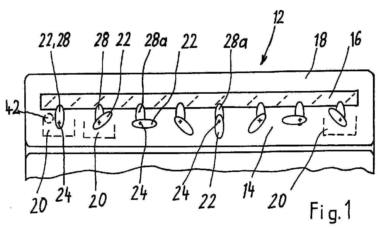
- a front panel 14 of the electric oven 12 is a symbol field 16 deepened, i.e. with respect to the front surface 18 of the panel 14 rear set back.
- the symbol field 16 contains symbols (not shown), which one operator the various functions of the stove Show.
- a plurality of rotary switches 20 are arranged behind the diaphragm 14. Any rotary switch is adjustable by a toggle 22, which is relative to the switch 20 and axially to one Axis of rotation 24, which is defined by a shaft 26, between an outer Axial position and an inner axial position through an opening 28 of the aperture axially displaceable and in the outer axial position from 0 ° to 360 ° or vice versa is rotatable about the axis of rotation 24 in different rotational positions.
- arrows 30 show the directions of rotation and arrows 32 the axial directions in which the Gag 22 is movable.
- the respective rotational position of the toggle 22 is by a Mark 34 on the symbol field 16 and by markings, for example 0, 1, 2 and 3, recognizable on the gag 22 for an operator.
- the outer periphery 40 of the portion of the toggle movable through the opening 28 22 has unequal radial center distances from the axis of rotation 24, and the edge of the opening 28 also has matched unequal center distances from the axis of rotation 24, such that the toggle 22 only through the opening 28 in the zero rotational position fits, but in no other rotational position.
- the axis of rotation 24 is for The center 41 of the oval shape or the ellipse is offset eccentrically and lies accordingly Fig.2 preferably on the long diameter axis of the oval shape or the long central axis of the ellipse.
- the outer circumference 40 lies in the outer axial position of the toggle 22 outside the opening 28 so that the toggle 22 can be rotated.
- the outer circumference 40 of the toggle 22 has a small in all axial positions of the toggle 22 Distance from the edge of the opening 28, so that one arranged behind the aperture 14 electric lighting device 42 light through the opening slit on the Front of the panel 14 can reach when the gag 22 from its inner Axial position is moved into its outer axial position and, preferably by this movement, the lighting device 42 is turned on.
- the front end face 44 of the toggle 22 is aligned with the front surface 18 of the Aperture 14 when the gag is in its inner axial position. This allows the Front of the panel 14 and the gag 22 can be easily cleaned and there will be Accidents, especially of children, are avoided since the recessed gag 22 can neither hit nor get caught.
- the gag 22 can be made from the part shown with the outer circumference 40 exist or have a further section behind this shown part, which extends through the opening 28 but has such a small diameter that it cannot collide with the opening edge.
- FIG. 2 shows the toggle 22 in its recessed, inner axial position, and in dashed lines Lines in its outer axial position, each in its zero-degree rotation position.
- 1 shows the toggle 22 in further rotational positions.
- Fig. 1 shows the good visibility the various rotational positions of the knob 22 for an operator. At any rotational position of the toggle 22 that deviates from the zero-degree rotational position is this on state of the switch 20 not only at the rotational position of the Knobs 22 recognizable, but also through the exposed part 28a of the opening 28, through which the light of the lighting device 42 then shines and an operator clearly signals that the associated switch electrical part, for example the oven, or a cooking zone or hotplate turned on and hot.
- the outer circumference 40 of the toggle 22 can also be other than an oval or elliptical To have shape. It is important that the outer circumference 40 of the opening 28 movable section of the toggle 22 unequal radial center distances from the Has axis of rotation 24 and that the edge of the opening 28 adapted uneven Has center distances from the axis of rotation 24, such that the gag only at his Zero rotational position through the opening 28 fits, but in no other of it 360 ° distributed rotary positions.
Landscapes
- Physics & Mathematics (AREA)
- General Physics & Mathematics (AREA)
- Engineering & Computer Science (AREA)
- Automation & Control Theory (AREA)
- Rotary Switch, Piano Key Switch, And Lever Switch (AREA)
- Switches With Compound Operations (AREA)
- Tumbler Switches (AREA)
Abstract
Drehschaltervorrichtung für elektrische Haushaltsgeräte. Der Außenumfang eines
durch eine Öffnung (28) einer Blende (14) versenkbaren Knebels (22) hat ungleiche
radiale Achsabstände von einer Drehachse (24) in gleicher Weise wie die Öffnung
(28), so daß der Knebel (22) nur in einer Null-Drehstellung durch die Öffnung (28)
passt, jedoch in keiner anderen Drehstellung.
Description
Die Erfindung betrifft eine Drehschaltervorrichtung für elektrische Haushaltsgeräte gemäß dem Oberbegriff von Anspruch 1.The invention relates to a rotary switch device for electrical household appliances according to the preamble of claim 1.
Vorrichtungen mit mindestens einem Drehschalter dieser Art sind aus der DE-C-33 45 312 bekannt. Sie zeigt einen Drehschalter mit einem Versenkknebel, welcher relativ zum eigentlichen Schalterteil und axial zu einer Drehachse zwischen einer äußeren Axialposition (Arbeitsposition) vor einer Blende und einer inneren Axialposition (Ruheposition) in einer Öffnung der Blende verschiebbar ist und in der äußeren Axialposition vor der Blende in verschiedene Drehstellungen um die Drehachse drehbar ist. Hinter der Blende kann eine Beleuchtungseinrichtung angeordnet sein zur Beleuchtung des Umfangsspaltes zwischen dem Rand der Blende und dem Knebel und/oder zur Beleuchtung von Symbolen, welche auf dem Knebel vorgesehen sind zur Kennzeichnung seiner eingestellten Funktion. Die Blende und/oder der Knebel können vollständig oder in Teilbereichen aus lichtdurchlässigemDevices with at least one rotary switch of this type are known from DE-C-33 45 312 known. It shows a rotary switch with a retractable toggle, which is relative to the actual switch part and axially to an axis of rotation between an outer Axial position (working position) in front of an aperture and an inner axial position (Rest position) is slidable in an opening of the diaphragm and in the outer axial position is rotatable about the axis of rotation in front of the aperture. A lighting device for lighting can be arranged behind the diaphragm the circumferential gap between the edge of the diaphragm and the gag and / or for lighting symbols which are provided on the gag for identification its set function. The aperture and / or the gag can be completely or in parts made of translucent
Material bestehen. Auf dem Knebel ist ein Steg angeordnet, welcher in Zusammenwirkung mit einem nicht-drehbar angeordneten Gegenstück eine axiale Verstellung des Knebels nur in einer vorbestimmten Drehstellung des Knebels erlaubt. Der Knebel kann eine Beleuchtungseinrichtung in Abhängigkeit von seiner Axialposition aktivieren. In der inneren Axialposition fluchtet die flache äußere Stirnfläche des Knebels mit der äußeren Oberfläche der Blende. Aus der DE-C-23 64 667 ist eine Betätigungsvorrichtung für hinter einer Blende angeordnete Schalt- oder Regeleinrichtungen von Herden zum Einstellen bestimmter Temperaturbereiche mit einem Knebel bekannt, welcher entgegen der Kraft einer Druckfeder in die Blende einschiebbar ist und in eingeschobener Stellung durch ein federndes Rastelement gehalten wird. Durch Druck auf den Knebel wird er von der Druckfeder von der inneren Axialposition in die äußere Axialposition verschoben. Die bekannten versenkbaren Knebel sind rund.Material. A web is arranged on the gag, which interacts with a non-rotatably arranged counterpart an axial adjustment of the Toggle allowed only in a predetermined rotational position of the toggle. The gag can activate a lighting device depending on its axial position. In the inner axial position, the flat outer face of the gag is flush with the outer surface of the bezel. From DE-C-23 64 667 is an actuator for switching or regulating devices of stoves arranged behind a panel known for setting certain temperature ranges with a gag, which against the force of a compression spring can be inserted into the panel and inserted Position is held by a resilient locking element. By pressing the It is gagged by the compression spring from the inner axial position to the outer axial position postponed. The well-known retractable gags are round.
Durch die Erfindung soll die Aufgabe gelöst werden, den Einschaltzustand und den Ausschaltzustand des Knebels auf einfache Weise besser erkennbar zu machen und die Bediensicherheit zu erhöhen.The object of the invention is to achieve the switch-on state and the To make the toggle switch-off state more easily recognizable and increase operational safety.
Diese Aufgabe wird gemäß der Erfindung durch die kennzeichnenden Merkmale von Anspruch 1 gelöst.This object is achieved according to the invention by the characterizing features of Claim 1 solved.
Die Erfindung ist dadurch gekennzeichnet, daß der Außenumfang des durch die Öffnung bewegbaren Abschnitts des Knebels ungleiche radiale Achsabstände von der Drehachse hat und daß der Rand der Öffnung ebenfalls daran angepaßte ungleiche Achsabstände von der Drehachse hat, derart, daß der Knebel nur in einer Null-Drehstellung durch die Öffnung paßt, jedoch in keiner anderen Drehstellung.The invention is characterized in that the outer circumference of the through the opening movable section of the toggle unequal radial center distances from the Has axis of rotation and that the edge of the opening also matched uneven Has center distances from the axis of rotation, such that the toggle only in a zero rotational position fits through the opening, but in no other rotational position.
Durch die Erfindung werden insbesondere zwei Vorteile erzielt. Einerseits ist gut erkennbar, ob sich der Knebel in der inneren Axialposition oder in der äußeren Axialposition befindet, ob er sich in der äußeren Axialposition in einer Null-Drehstellung befindet, bei welcher er in die Öffnung der Blende hinein zur inneren Axialstellung verschiebbar ist, oder ob er in der äußeren Axialposition in einer anderen Drehstellung ist. Für die Funktion, daß der Knebel nur in seiner Null-Drehstellung von der äußeren Axialposition in die Öffnung hinein zur inneren Axialposition bewegt werden kann, sind keine zusätzlichen Mittel erforderlich.In particular, two advantages are achieved by the invention. On the one hand, it is easy to see whether the gag is in the inner axial position or in the outer axial position whether it is in a zero rotary position in the outer axial position, in which it can be moved into the opening of the diaphragm to the inner axial position or whether it is in a different rotational position in the outer axial position. For the function that the knob is only in its zero rotary position from the outer Axial position can be moved into the opening to the inner axial position no additional funds required.
Bei Verwendung bei einem Elektroherd können z.B. folgende Funktionen vorgesehen sein: Bei Null-Drehstellung des Knebels in der inneren Axialposition sind eine bestimmte Heizvorrichtung (Kochzone, Kochplatte, Backofen) und eine Beleuchtung des Knebels oder seiner Umgebung ausgeschaltet. Bei Null-Drehstellung in der äußeren Axialposition ist nur die Beleuchtung eingeschaltet. Bei einer von Null abweichenden Drehstellung sind die Beleuchtung und die Heizung eingeschaltet, wobei je nach Drehstellung des Knebels eine vorbestimmte Heizleistung eingeschaltet ist. When used with an electric cooker, e.g. the following functions are provided be: With the toggle in the inner axial position, there is a certain one Heating device (cooking zone, hot plate, oven) and lighting of the Knebels or its surroundings turned off. With zero rotary position in the outer Only the lighting is switched on in the axial position. With a non-zero The lighting and heating are switched on, depending on the Rotary position of the toggle a predetermined heating power is turned on.
Die Erfindung bietet auch eine zuverlässige ![]()
![]()
Weitere Merkmale der Erfindung sind in den Unteransprüchen enthalten.Further features of the invention are contained in the subclaims.
Die Erfindung wird im folgenden mit Bezug auf die Zeichnungen anhand einer bevorzugten Ausführungsform als Beispiel beschrieben.The invention is in the following with reference to the drawings based on a preferred Embodiment described as an example.
Es zeigen:
- Figur 1
- eine abgebrochene Vorderansicht eines Elektroherdes mit einer Drehschaltervorrichtung, die mehrere Drehschalter gemäß der Erfindung enthält,
- Figur 2
- eine perspektivische Vorderansicht eines Teiles von Figur 1 mit einem versenkbaren Knebel eines Drehschalters gemäß der Erfindung.
- Figure 1
- FIG. 2 shows a broken front view of an electric cooker with a rotary switch device which contains a plurality of rotary switches according to the invention,
- Figure 2
- a front perspective view of a part of Figure 1 with a retractable toggle of a rotary switch according to the invention.
Die Erfindung wird im folgenden mit Bezug auf die Zeichnungen in Verbindung mit einem
Elektroherd 12 beschrieben, kann jedoch auch für beliebige andere Haushaltsgeräte
verwendet werden, beispielsweise für Geschirrspüler, Waschmaschinen,
Rührmaschinen, usw. In einer vorderen Blende 14 des Elektroherdes 12 ist ein Symbolfeld
16 vertieft, d.h. mit Bezug auf die vordere Oberfläche 18 der Blende 14 nach
hinten zurückversetzt angeordnet. Das Symbolfeld 16 enthält Symbole (nicht dargestellt),
welche einer Bedienungsperson die verschiedenen Funktionen des Herdes
anzeigen.The invention will be described in the following with reference to the drawings in connection with a
Hinter der Blende 14 sind mehrere Drehschalter 20 angeordnet. Jeder Drehschalter
ist durch einen Knebel 22 einstellbar, welcher relativ zum Schalter 20 und axial zu einer
Drehachse 24, die durch eine Welle 26 definiert ist, zwischen einer äußeren
Axialposition und einer inneren Axialposition durch eine Öffnung 28 der Blende hindurch
axial verschiebbar und in der äußeren Axialposition von 0° bis 360° oder umgekehrt
in verschiedene Drehstellungen um die Drehachse 24 drehbar ist. In Figur 2
zeigen Pfeile 30 die Drehrichtungen und Pfeile 32 die Axialrichtungen, in welche der
Knebel 22 bewegbar ist. Die jeweilige Drehstellung des Knebels 22 ist durch eine
Markierung 34 auf dem Symbolfeld 16 und durch Markierungen, beispielsweise 0, 1,
2 und 3, auf dem Knebel 22 für eine Bedienungsperson erkennbar.A plurality of
Der Außenumfang 40 des durch die Öffnung 28 bewegbaren Abschnitt des Knebels
22 hat ungleiche radiale Achsabstände von der Drehachse 24, und der Rand der Öffnung
28 hat ebenfalls daran angepasste ungleiche Achabstände von der Drehachse
24, derart, daß der Knebel 22 nur in der Null-Drehstellung durch die Öffnung 28
passt, jedoch in keiner anderen Drehstellung.The outer periphery 40 of the portion of the toggle movable through the
Der Außenumfang 40 des Knebels 22 und die daran angepasste Öffnung 28 haben
eine ovale Form, beispielsweise die Form einer Ellipse. Die Drehachse 24 ist zum
Mittelpunkt 41 der ovalen Form oder der Ellipse exzentrisch versetzt und liegt entsprechend
Fig.2 vorzugsweise auf der langen Durchmesserachse der ovalen Form
bzw. der langen Mittelachse der Ellipse.The outer periphery 40 of the
In der äußeren Axialposition des Knebels 22 liegt sein genannter Außenumfang 40
außerhalb der Öffnung 28, damit der Knebel 22 gedreht werden kann. Der Außenumfang
40 des Knebels 22 hat bei allen Axialpositionen des Knebels 22 einen kleinen
Abstand vom Rand der Öffnung 28, so daß von einer hinter der Blende 14 angeordneten
elektrischen Beleuchtungsvorrichtung 42 Licht durch den Öffnungsspalt auf die
Vorderseite der Blende 14 gelangen kann, wenn der Knebel 22 von seiner inneren
Axialposition in seine äußere Axialposition bewegt wird und, vorzugsweise durch
diese Bewegung, die Beleuchtungsvorrichtung 42 eingeschaltet wird.Its outer circumference 40 lies in the outer axial position of the
Die vordere Stirnseite 44 des Knebels 22 fluchtet mit der vorderen Oberfläche 18 der
Blende 14, wenn der Knebel in seiner inneren Axialposition ist. Dadurch kann die
Vorderseite der Blende 14 und der Knebel 22 leicht gereinigt werden und es werden
Unfälle, inbesondere von Kindern, vermieden, da man an dem versenkten Knebel 22
weder anstoßen noch hängenbleiben kann.The
Der Knebel 22 kann insgesamt aus dem dargestellten Teil mit dem Außenumfang 40
bestehen oder hinter diesem dargestellten Teil einen weiteren Abschnitt haben, welcher
sich durch die Öffnung 28 erstreckt, jedoch einen so kleinen Durchmesser hat,
daß er mit dem Öffnungsrand nicht kollidieren kann.The
Fig.2 zeigt den Knebel 22 in seiner versenkten, inneren Axialposition, und in gestrichelten
Linien in seiner äußeren Axialposition, je in seiner Null-Grad-Drehstellung.
Fig.1 zeigt den Knebel 22 in weiteren Drehstellungen. Fig.1 zeigt die gute Erkennbarkeit
der verschiedenen Drehstellungen des Knebels 22 für eine Bedienungsperson.
Bei jeder von der Null-Grad-Drehstellung abweichenden Drehstellung des Knebels 22
ist dieser eingeschaltete Zustand des Schalters 20 nicht nur an der Drehstellung des
Knebels 22 erkennbar, sondern auch durch den dabei freigelegten Teil 28a der Öffnung
28, durch welche dann das Licht der Beleuchtungsvorrichtung 42 scheint und
einer Bedienungsperson deutlich signalisiert daß das diesem Schalter zugehörige
elektrische Teil, beispielsweise der Backofen, oder eine Kochzone oder Kochplatte
eingeschaltet und heiß ist.2 shows the
Der Außenumfang 40 des Knebels 22 kann auch eine andere als eine ovale oder elliptische
Form haben. Wichtig ist, daß der Außenumfang 40 des durch die Öffnung 28
bewegbaren Abschnitts des Knebels 22 ungleiche radiale Achsabstände von der
Drehachse 24 hat und daß auch der Rand der Öffnung 28 daran angepasste ungleiche
Achsabstände von der Drehachse 24 hat, derart, daß der Knebel nur bei seiner
Null-Drehstellung durch die Öffnung 28 paßt, jedoch in keiner anderen seiner über
360° verteilten Drehstellungen.The outer circumference 40 of the
Claims (6)
Applications Claiming Priority (2)
| Application Number | Priority Date | Filing Date | Title |
|---|---|---|---|
| DE1998105558 DE19805558A1 (en) | 1998-02-11 | 1998-02-11 | Rotary switch device for electrical household appliances |
| DE19805558 | 1998-02-11 |
Publications (3)
| Publication Number | Publication Date |
|---|---|
| EP0936643A2 true EP0936643A2 (en) | 1999-08-18 |
| EP0936643A3 EP0936643A3 (en) | 2000-11-02 |
| EP0936643B1 EP0936643B1 (en) | 2007-08-15 |
Family
ID=7857382
Family Applications (1)
| Application Number | Title | Priority Date | Filing Date |
|---|---|---|---|
| EP99101667A Expired - Lifetime EP0936643B1 (en) | 1998-02-11 | 1999-02-04 | Rotary switch assembly for electrical domestic devices |
Country Status (3)
| Country | Link |
|---|---|
| EP (1) | EP0936643B1 (en) |
| DE (2) | DE19805558A1 (en) |
| ES (1) | ES2292213T3 (en) |
Cited By (1)
| Publication number | Priority date | Publication date | Assignee | Title |
|---|---|---|---|---|
| EP1387371A2 (en) | 2002-08-03 | 2004-02-04 | Electrolux Home Products Corporation N.V. | Retractable turning-knob assembly |
Families Citing this family (6)
| Publication number | Priority date | Publication date | Assignee | Title |
|---|---|---|---|---|
| DE10214920A1 (en) * | 2002-04-04 | 2003-10-16 | Bsh Bosch Siemens Hausgeraete | Control unit and cooking device |
| DE102004049691A1 (en) * | 2004-10-12 | 2006-04-13 | BSH Bosch und Siemens Hausgeräte GmbH | Operating device for e.g. electric cooker, has controller concealing preselectable operating states, and switching device is attached to controller for acquire sinking of turning toggle to cancel strength of selected operating state |
| DE102006048418A1 (en) * | 2006-10-12 | 2008-04-17 | BSH Bosch und Siemens Hausgeräte GmbH | Domestic appliance with rotary knob |
| DE102006061201A1 (en) * | 2006-12-22 | 2008-06-26 | BSH Bosch und Siemens Hausgeräte GmbH | Domestic appliance adjustment device for domestic appliance, particularly for cooking device, has illumination unit with light unit, which is provided to one of display units relative to another display unit |
| DE102009008192A1 (en) * | 2009-02-03 | 2010-08-05 | E.G.O. Elektro-Gerätebau GmbH | Control device for an electrical appliance and operating method |
| US12163668B2 (en) | 2020-09-11 | 2024-12-10 | Midea Group Co., Ltd. | Apparatus for reducing undesired change in cooking appliance configuration |
Family Cites Families (6)
| Publication number | Priority date | Publication date | Assignee | Title |
|---|---|---|---|---|
| US2367892A (en) * | 1943-09-23 | 1945-01-23 | Charles A Schallis | Control handle |
| DE2364667C2 (en) * | 1973-12-24 | 1982-08-05 | Neff - Werke, Carl Neff Gmbh, 7518 Bretten | Actuating device for the switching or control devices of stoves arranged behind a switch panel |
| DE3345312C2 (en) * | 1983-12-14 | 1986-02-06 | Bosch-Siemens Hausgeräte GmbH, 7000 Stuttgart | Rotary switch for household appliances with a rotary knob that can be retracted axially displaceably in the front of the device |
| DE3702291A1 (en) * | 1987-01-27 | 1988-08-04 | Buderus Kuechentechnik | DEVICE FOR ADJUSTING THE SWITCHES AND CONTROL DEVICES OF A HOUSEHOLD APPLIANCE |
| GB8825104D0 (en) * | 1988-10-26 | 1988-11-30 | New World Domestic Appliances | Rotary control knobs |
| DE8905409U1 (en) * | 1989-04-28 | 1989-07-06 | Wilfer, Hertwig, 6083 Biebesheim | Child safety switch button for household appliances |
-
1998
- 1998-02-11 DE DE1998105558 patent/DE19805558A1/en not_active Withdrawn
-
1999
- 1999-02-04 ES ES99101667T patent/ES2292213T3/en not_active Expired - Lifetime
- 1999-02-04 DE DE59914450T patent/DE59914450D1/en not_active Expired - Lifetime
- 1999-02-04 EP EP99101667A patent/EP0936643B1/en not_active Expired - Lifetime
Cited By (3)
| Publication number | Priority date | Publication date | Assignee | Title |
|---|---|---|---|---|
| EP1387371A2 (en) | 2002-08-03 | 2004-02-04 | Electrolux Home Products Corporation N.V. | Retractable turning-knob assembly |
| EP1387371A3 (en) * | 2002-08-03 | 2005-09-28 | Electrolux Home Products Corporation N.V. | Retractable turning-knob assembly |
| EP2546845A3 (en) * | 2002-08-03 | 2013-03-13 | Electrolux Home Products Corporation N.V. | Retractable turning-knob assembly |
Also Published As
| Publication number | Publication date |
|---|---|
| DE19805558A1 (en) | 1999-08-12 |
| DE59914450D1 (en) | 2007-09-27 |
| EP0936643A3 (en) | 2000-11-02 |
| ES2292213T3 (en) | 2008-03-01 |
| EP0936643B1 (en) | 2007-08-15 |
Similar Documents
| Publication | Publication Date | Title |
|---|---|---|
| EP1869368B1 (en) | Operator control device for an electric appliance | |
| DE2830249C2 (en) | Release device for a clutch | |
| DE10255676B4 (en) | Control unit for an electrical device | |
| DE4017422C2 (en) | ||
| DE3345312A1 (en) | ROTARY SWITCH FOR HOUSEHOLD APPLIANCES WITH A ROTARY TURN SWITCHING AXIAL SLIDING IN THE DEVICE FRONT | |
| EP0936643B1 (en) | Rotary switch assembly for electrical domestic devices | |
| DE69013351T2 (en) | CONTROL LEVER. | |
| DE3637451A1 (en) | Rotary knob for temperature adjustment | |
| DE2702839B2 (en) | Rotary switch for vehicles, electrically illuminated from the inside, with symbol lighting and position indicator | |
| EP3748234B1 (en) | Operating device for an electrical device and method for producing an electrical device | |
| DE3637505A1 (en) | Rotary knob having a rotational locking and unlocking device | |
| DE29824658U1 (en) | Rotary switch device for electrical household appliances | |
| DE1665800B2 (en) | Rotary switch drive | |
| EP2224832B1 (en) | Housing having an assembly disposed therein | |
| DE3018416A1 (en) | Control switch for hotplate or heat storage device - has rotary setting member also operating switch that connects in extra heating element | |
| DE4309033C2 (en) | Safety switching device for electrical devices | |
| DE4013074A1 (en) | ADJUSTABLE DEVICE, ESPECIALLY ELECTRICAL SWITCHING, CONTROL OR REGULATING DEVICE | |
| EP0177811B1 (en) | Control switch | |
| EP2092644A2 (en) | Operating device for an electric appliance comprising contact switches and method for switching on a supplementary heating device | |
| DE4331551B4 (en) | Main switch for a household electrical appliance | |
| DE102004020977B4 (en) | Device for variably adjusting the power of a heating device with at least two heating circuits | |
| DE4203427C2 (en) | Cam rotary switch | |
| DE10324251A1 (en) | keypad | |
| DE19820446C2 (en) | Energy regulator of an electric cooker | |
| EP2136145A2 (en) | Operating knob for a domestic appliance |
Legal Events
| Date | Code | Title | Description |
|---|---|---|---|
| PUAI | Public reference made under article 153(3) epc to a published international application that has entered the european phase |
Free format text: ORIGINAL CODE: 0009012 |
|
| AK | Designated contracting states |
Kind code of ref document: A2 Designated state(s): DE ES FR GB IT |
|
| AX | Request for extension of the european patent |
Free format text: AL;LT;LV;MK;RO;SI |
|
| PUAL | Search report despatched |
Free format text: ORIGINAL CODE: 0009013 |
|
| AK | Designated contracting states |
Kind code of ref document: A3 Designated state(s): AT BE CH CY DE DK ES FI FR GB GR IE IT LI LU MC NL PT SE |
|
| AX | Request for extension of the european patent |
Free format text: AL;LT;LV;MK;RO;SI |
|
| 17P | Request for examination filed |
Effective date: 20001114 |
|
| AKX | Designation fees paid |
Free format text: DE ES FR GB IT |
|
| EL | Fr: translation of claims filed | ||
| RAP1 | Party data changed (applicant data changed or rights of an application transferred) |
Owner name: BSH BOSCH UND SIEMENS HAUSGERAETE GMBH |
|
| GRAP | Despatch of communication of intention to grant a patent |
Free format text: ORIGINAL CODE: EPIDOSNIGR1 |
|
| GRAS | Grant fee paid |
Free format text: ORIGINAL CODE: EPIDOSNIGR3 |
|
| GRAA | (expected) grant |
Free format text: ORIGINAL CODE: 0009210 |
|
| AK | Designated contracting states |
Kind code of ref document: B1 Designated state(s): DE ES FR GB IT |
|
| REG | Reference to a national code |
Ref country code: GB Ref legal event code: FG4D Free format text: NOT ENGLISH |
|
| REF | Corresponds to: |
Ref document number: 59914450 Country of ref document: DE Date of ref document: 20070927 Kind code of ref document: P |
|
| GBT | Gb: translation of ep patent filed (gb section 77(6)(a)/1977) |
Effective date: 20071122 |
|
| REG | Reference to a national code |
Ref country code: ES Ref legal event code: FG2A Ref document number: 2292213 Country of ref document: ES Kind code of ref document: T3 |
|
| EN | Fr: translation not filed | ||
| PLBE | No opposition filed within time limit |
Free format text: ORIGINAL CODE: 0009261 |
|
| STAA | Information on the status of an ep patent application or granted ep patent |
Free format text: STATUS: NO OPPOSITION FILED WITHIN TIME LIMIT |
|
| 26N | No opposition filed |
Effective date: 20080516 |
|
| PGFP | Annual fee paid to national office [announced via postgrant information from national office to epo] |
Ref country code: ES Payment date: 20100219 Year of fee payment: 12 |
|
| PGFP | Annual fee paid to national office [announced via postgrant information from national office to epo] |
Ref country code: IT Payment date: 20100227 Year of fee payment: 12 |
|
| PGFP | Annual fee paid to national office [announced via postgrant information from national office to epo] |
Ref country code: GB Payment date: 20100219 Year of fee payment: 12 Ref country code: DE Payment date: 20100228 Year of fee payment: 12 |
|
| GBPC | Gb: european patent ceased through non-payment of renewal fee |
Effective date: 20110204 |
|
| PG25 | Lapsed in a contracting state [announced via postgrant information from national office to epo] |
Ref country code: IT Free format text: LAPSE BECAUSE OF NON-PAYMENT OF DUE FEES Effective date: 20110204 |
|
| REG | Reference to a national code |
Ref country code: DE Ref legal event code: R119 Ref document number: 59914450 Country of ref document: DE Effective date: 20110901 |
|
| PG25 | Lapsed in a contracting state [announced via postgrant information from national office to epo] |
Ref country code: GB Free format text: LAPSE BECAUSE OF NON-PAYMENT OF DUE FEES Effective date: 20110204 |
|
| REG | Reference to a national code |
Ref country code: ES Ref legal event code: FD2A Effective date: 20120411 |
|
| PG25 | Lapsed in a contracting state [announced via postgrant information from national office to epo] |
Ref country code: ES Free format text: LAPSE BECAUSE OF NON-PAYMENT OF DUE FEES Effective date: 20110205 |
|
| PG25 | Lapsed in a contracting state [announced via postgrant information from national office to epo] |
Ref country code: FR Free format text: LAPSE BECAUSE OF FAILURE TO SUBMIT A TRANSLATION OF THE DESCRIPTION OR TO PAY THE FEE WITHIN THE PRESCRIBED TIME-LIMIT Effective date: 20080411 |
|
| PG25 | Lapsed in a contracting state [announced via postgrant information from national office to epo] |
Ref country code: DE Free format text: LAPSE BECAUSE OF NON-PAYMENT OF DUE FEES Effective date: 20110901 |