EP0936714A2 - Improvements in electric energy conducting installations - Google Patents
Improvements in electric energy conducting installations Download PDFInfo
- Publication number
- EP0936714A2 EP0936714A2 EP98500005A EP98500005A EP0936714A2 EP 0936714 A2 EP0936714 A2 EP 0936714A2 EP 98500005 A EP98500005 A EP 98500005A EP 98500005 A EP98500005 A EP 98500005A EP 0936714 A2 EP0936714 A2 EP 0936714A2
- Authority
- EP
- European Patent Office
- Prior art keywords
- strips
- holes
- bars
- electric energy
- conductor
- Prior art date
- Legal status (The legal status is an assumption and is not a legal conclusion. Google has not performed a legal analysis and makes no representation as to the accuracy of the status listed.)
- Granted
Links
- 238000009434 installation Methods 0.000 title claims abstract description 16
- 239000004020 conductor Substances 0.000 claims abstract description 20
- 238000009413 insulation Methods 0.000 claims abstract description 12
- 229910052751 metal Inorganic materials 0.000 claims abstract description 12
- 239000002184 metal Substances 0.000 claims abstract description 12
- 229920005989 resin Polymers 0.000 claims abstract description 12
- 239000011347 resin Substances 0.000 claims abstract description 12
- XAGFODPZIPBFFR-UHFFFAOYSA-N aluminium Chemical compound [Al] XAGFODPZIPBFFR-UHFFFAOYSA-N 0.000 claims abstract description 6
- 229910052782 aluminium Inorganic materials 0.000 claims abstract description 5
- 238000001816 cooling Methods 0.000 claims description 8
- 230000000903 blocking effect Effects 0.000 claims 1
- 238000007789 sealing Methods 0.000 claims 1
- 238000000926 separation method Methods 0.000 abstract 1
- 230000008602 contraction Effects 0.000 description 2
- 230000005672 electromagnetic field Effects 0.000 description 2
- RYGMFSIKBFXOCR-UHFFFAOYSA-N Copper Chemical compound [Cu] RYGMFSIKBFXOCR-UHFFFAOYSA-N 0.000 description 1
- 239000004952 Polyamide Substances 0.000 description 1
- 238000009833 condensation Methods 0.000 description 1
- 230000005494 condensation Effects 0.000 description 1
- 229910052802 copper Inorganic materials 0.000 description 1
- 239000010949 copper Substances 0.000 description 1
- 239000003822 epoxy resin Substances 0.000 description 1
- 238000009313 farming Methods 0.000 description 1
- 239000012212 insulator Substances 0.000 description 1
- 239000000463 material Substances 0.000 description 1
- 229920006122 polyamide resin Polymers 0.000 description 1
- 229920000647 polyepoxide Polymers 0.000 description 1
- 230000002265 prevention Effects 0.000 description 1
Images

Classifications
-
- H—ELECTRICITY
- H02—GENERATION; CONVERSION OR DISTRIBUTION OF ELECTRIC POWER
- H02G—INSTALLATION OF ELECTRIC CABLES OR LINES, OR OF COMBINED OPTICAL AND ELECTRIC CABLES OR LINES
- H02G5/00—Installations of bus-bars
- H02G5/06—Totally-enclosed installations, e.g. in metal casings
Definitions
- This invention relates to a series of improvements introduced in electric energy conducting installations, said improvements addressing both the means of mounting and insulating the bars which form the electrical conductors and the means of channelling said bars.
- the installations to which the improvements of the invention apply are known as medium voltage electric lines, and are used particularly in power plants, large factories and locations where electric energy transport and distribution is called for.
- Spanish invention patent No. 470.796 describes a medium voltage electric line channelling based on a plurality of insulated strips embedded in several layers of resin, the assembly being enclosed in a metal housing acting both as a screen against the resulting electric and magnetic fields and as a protection device.
- the channelling obtained through the improvements claimed in the above invention patent No. 470.196 provides a set of segregated phase bars that are highly resistant to short-circuits and furthermore prevents problems in regard to condensations which until now have been evident in convectional channelling by completely removing the air inside the sheath, namely between the conductor and the conductor insulating layer, based precisely on the arrangement of the bars embedded within the insulating resin layers.
- the conduction or channelling based on the improvements of invention patent No. 470.796 is affected by several problems and inconveniences such as failing to achieve an efficient cooling as a result of the metal sheath being fully closed along its perimeter.
- the installation or channelling described in the above invention patent fails to take into account the arrangement of the bars forming the three phases of a medium voltage electrical line, the support means in the event that the bars are separated and embedded in individual molds, and the arrangement of the conduction bar strips nearer to each other.
- the advocated improvements applicable to medium voltage electric energy conduction lines are foreseen not only for solving the above problems but also as a means of providing additional functions and an optimal structure for the installation or channelling of electric energy conducts.
- one of the improvements of the invention consists in that the connecting ends of the strips which form the conductors include holes with built-in threading allowing the connections to be extended and the strips to be positioned closer to each other. Furthermore, the connections between the strips are additionally fitted with a thermally formed sheath enabling demolding, when necessary.
- the metal sheath for the installation or channelling is formed by aluminum plate sections with drilled-in holes providing improved cooling features, the shapes being attached to each other to form the channelling proper, said attachment involving parts which are inserted between the various lengths forming the overall channelling extension.
- a further improvement of the invention lies in the fact that the conductor strips hold the ends of the insulating elements, which are fitted with steps providing a gap between the strips at the point where the strips are no longer insulated, thus providing a further sliding length, the strips being slidable in respect to the insulation.
- Figure 3 shows a detail of a perspective view of an individually mounted conductor bar.
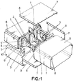
- the installation or channelling of the electric energy conducting bars comprises conductor strips (1) at the ends of which holes are provided, said holes being fitted with embedded threads (2) for the screws which attach the plates (3) which form the attachment elements between said strips (1), which strips are covered with a resin, polyamide or epoxy resin insulating sheath (4), said sheath (4) forming or determining steps in said end portions of the strips (1) which separate the strips from one another when no longer insulated, as can be seen in Figures 1 and 3, thus enlarging the sliding length and providing added safety to the installation.
- the insulation provided by the resins (4) is complemented with an insulating cover (5) which in turn is embedded in a further covering layer (5'), thus forming the corresponding electric energy conducting bar.
- the bars as shown in Figure 1 are arranged inside the metal housing (6) formed by a series of metal - specifically aluminum - shapes or sheets (7) with wing (8) farming edges which adhere longitudinally to one another via rivets, the plates (7) being attached to each other along their perimeter by intermediate attachment parts (9), said parts (9) and plates (7) also being provided with holes (10) for inserting the attachment rivets or screws, the plates (7) also having additional holes (15) for cooling purposes.
- the metal housing (6) thus formed serves to conduct the ground and induced currents and to enclose the three grouped and balanced phases forming the respective conductor bars constructed according to the above description.
- the metal housing (6) made of aluminum and provided with holes, not only enables ground connection and provides an effective sheathing means by considerably reducing the outward-leading electromagnetic field but also prevents distortions to the electronic equipment and the hot points of the metal structures, in addition to preventing access to live voltage and hot areas.
- the ends of the individual elements (11) provided along the conductor bar are fitted with rods (12) for securing the assembly to the insulating supports (13) via the lodging of the rods (12) inside the holes (14) in said insulating supports (13), which in turn provide a means of attachment of each bar module to the assembly and of the latter to the structure onto which the channelling is mounted.
- the insulating cover (4) on each strip (1) separating the strip from the corresponding cooling mass or insulation (5), allows for individual expansion and contraction, thus preventing failures occurring in parts adhered to each other as a result of the different expansion coefficients of the copper in the strips (1) and the insulating/cooling mass.
- the resins which form the insulating cover (4) on the strips (1) provide a means of separating the strips (1) from the insulating layer (5) and allow the strips to slide inside the insulation, thus avoiding fractures which normally occur when both parts are secured to one another.
- the attachment of a module bar to a subsequent bar is performed inside a thermally formed module which provides a protection upon filling the connection and allows the bar to operate through expansion and contraction when the current is either flowing or not flowing, without affecting the external cooling sheath.
Landscapes
- Shielding Devices Or Components To Electric Or Magnetic Fields (AREA)
- Linear Motors (AREA)
- Non-Insulated Conductors (AREA)
Abstract
Description
- Resilient attachments throughout the length of the installation.
- Rapid and secure assembly through nuts embedded in the conductor plate end attachment lengths.
- Rational grouping of the conductor strips.
- Greater installation safety deriving from the steps corresponding to the insulation or resins provided at the plate ends.
- Prevention of insulation failures through an inner insulator which separates the resin expansions and acts as a means of insulation for the strips which form the conductors.
- Insulation of the electromagnetic fields based on the external magnetic housing formed by the perforated aluminum metal envelope.
- Attachment blocks, independent from one phase to the other, even in the grouped models, for the purpose of facilitating the dismounting operation.
Claims (2)
- Improvements in electric energy conducting installations applicable to the type of installation formed by bars composed of conductor strips (1) embedded in a layer of insulating cover (4) based on resins, the overall assembly being installed under a layer of cooling insulation (5) complemented by an additional cover (5'), also of an insulating nature, characteristic in that the resin insulating cover (4) at the ends of the strips (1) forms steps which separate the non-insulated ends of the strips (1) from one another, a special feature being provided in that said strip (1) end portions are provided with holes fitted with embedded threads (2) for the screws which attach the strips (1) axially to one another through lateral plates (3), the attachment being complemented with a thermally formed sheath which, upon sealing the connection, prevents the resin from blocking the electric connection and thus allows the sliding of the bars, an additional feature consisting in that the conductor bars forming the strips (1), cover and insulation are arranged inside a metal housing (6) formed by aluminum sheets (7) with cooling holes (11), which sheets (7) are fitted with end wings (8) mutually attached by means of rivets or screws, the perimeter attachment of the sheets (7) using intermediate parts (9) also fitted with holes (10) for inserting of the attachment rivets or screws.
- Improvements in electric energy conducting installations, according to claim 1, characteristic in that the individually mounted conductor bars are attached to respective insulating supports (13) through which the assembly is in turn adhered to the general structure onto which is mounted the channelling, the mounting onto said insulating supports (13) involving rods (12) lodged in holes (14) drilled in the supports (13), which rods pertain to individual elements (11) forming a part of the module or corresponding conductor bar.
Priority Applications (2)
| Application Number | Priority Date | Filing Date | Title |
|---|---|---|---|
| EP19980500005 EP0936714B9 (en) | 1998-01-14 | 1998-01-14 | Improvements in electric energy conducting installations |
| DE69830978T DE69830978T2 (en) | 1998-01-14 | 1998-01-14 | IMPROVEMENTS OF INSTALLATIONS FOR POWER SUPPLY |
Applications Claiming Priority (1)
| Application Number | Priority Date | Filing Date | Title |
|---|---|---|---|
| EP19980500005 EP0936714B9 (en) | 1998-01-14 | 1998-01-14 | Improvements in electric energy conducting installations |
Publications (4)
| Publication Number | Publication Date |
|---|---|
| EP0936714A2 true EP0936714A2 (en) | 1999-08-18 |
| EP0936714A3 EP0936714A3 (en) | 2000-08-09 |
| EP0936714B1 EP0936714B1 (en) | 2005-07-27 |
| EP0936714B9 EP0936714B9 (en) | 2006-03-08 |
Family
ID=8235803
Family Applications (1)
| Application Number | Title | Priority Date | Filing Date |
|---|---|---|---|
| EP19980500005 Expired - Lifetime EP0936714B9 (en) | 1998-01-14 | 1998-01-14 | Improvements in electric energy conducting installations |
Country Status (2)
| Country | Link |
|---|---|
| EP (1) | EP0936714B9 (en) |
| DE (1) | DE69830978T2 (en) |
Cited By (5)
| Publication number | Priority date | Publication date | Assignee | Title |
|---|---|---|---|---|
| DE102004020631A1 (en) * | 2004-04-27 | 2005-12-01 | Siemens Ag | Sound-absorbing lining for a sheet metal housing |
| EP1786079A1 (en) * | 2005-11-14 | 2007-05-16 | Bticino S.P.A. | Electrical end connector for a prefabricated leaktight conduit member for the distribution of electrical power |
| CN103647242A (en) * | 2013-12-04 | 2014-03-19 | 江苏省电力设计院 | Connection structure of box-sharing enclosed buses |
| CN112421491A (en) * | 2020-09-27 | 2021-02-26 | 国网浙江海盐县供电有限公司 | A live installation tool for easy installation of insulating cover |
| IT202300002754A1 (en) * | 2023-02-17 | 2024-08-17 | Eae Elektrik Asansor Endustri Insaat Sanayi Ve Ticaret Anonim Sir | SCREENED BUSBAR |
Families Citing this family (1)
| Publication number | Priority date | Publication date | Assignee | Title |
|---|---|---|---|---|
| CN112653050A (en) * | 2020-12-14 | 2021-04-13 | 杭州易正科技有限公司 | Telescopic bus duct connector |
Family Cites Families (4)
| Publication number | Priority date | Publication date | Assignee | Title |
|---|---|---|---|---|
| US3346687A (en) * | 1966-08-05 | 1967-10-10 | Gen Electric | Electric power busway having non-selfadhering insulation between the busbars and between the housing and the busbars |
| US4658504A (en) * | 1985-08-23 | 1987-04-21 | Westinghouse Electric Corp. | Method for insulating conductor joints particularly bus bars and insulated bus bar apparatus |
| FR2630270A1 (en) * | 1988-04-19 | 1989-10-20 | Erico France Sarl | ELECTRICAL CONNECTION AND POWER SUPPLY SYSTEM |
| ES2108628B1 (en) * | 1995-03-09 | 1998-10-01 | Isobusbar S L | PROCEDURE FOR THE MANUFACTURE OF ELECTRICAL DUCTING AND DUCTING OBTAINED BY SUCH PROCEDURE. |
-
1998
- 1998-01-14 DE DE69830978T patent/DE69830978T2/en not_active Expired - Fee Related
- 1998-01-14 EP EP19980500005 patent/EP0936714B9/en not_active Expired - Lifetime
Cited By (10)
| Publication number | Priority date | Publication date | Assignee | Title |
|---|---|---|---|---|
| DE102004020631A1 (en) * | 2004-04-27 | 2005-12-01 | Siemens Ag | Sound-absorbing lining for a sheet metal housing |
| DE102004020631B4 (en) * | 2004-04-27 | 2006-03-02 | Siemens Ag | Sound-absorbing lining for a sheet metal housing |
| EP1786079A1 (en) * | 2005-11-14 | 2007-05-16 | Bticino S.P.A. | Electrical end connector for a prefabricated leaktight conduit member for the distribution of electrical power |
| WO2007054247A1 (en) * | 2005-11-14 | 2007-05-18 | Bticino S.P.A. | Electrical end connector for a prefabricated leaktight conduit member for the distribution of electrical power |
| CN103647242A (en) * | 2013-12-04 | 2014-03-19 | 江苏省电力设计院 | Connection structure of box-sharing enclosed buses |
| CN103647242B (en) * | 2013-12-04 | 2016-06-22 | 中国能源建设集团江苏省电力设计院有限公司 | A kind of Gong Xiang enclosed busbar UNICOM structure |
| CN112421491A (en) * | 2020-09-27 | 2021-02-26 | 国网浙江海盐县供电有限公司 | A live installation tool for easy installation of insulating cover |
| CN112421491B (en) * | 2020-09-27 | 2022-03-11 | 国网浙江海盐县供电有限公司 | A live installation tool for easy installation of insulating cover |
| IT202300002754A1 (en) * | 2023-02-17 | 2024-08-17 | Eae Elektrik Asansor Endustri Insaat Sanayi Ve Ticaret Anonim Sir | SCREENED BUSBAR |
| EP4418480A1 (en) | 2023-02-17 | 2024-08-21 | EAE Elektrik Asansor Endustri Insaat Sanayi Veticaret Anonim Sir | Shielded busbar |
Also Published As
| Publication number | Publication date |
|---|---|
| DE69830978T2 (en) | 2006-05-24 |
| EP0936714A3 (en) | 2000-08-09 |
| EP0936714B1 (en) | 2005-07-27 |
| EP0936714B9 (en) | 2006-03-08 |
| DE69830978D1 (en) | 2005-09-01 |
Similar Documents
| Publication | Publication Date | Title |
|---|---|---|
| CA1309473C (en) | Thermally efficient power busway housing | |
| CN102474082B (en) | Power switchgear | |
| US9520688B2 (en) | Joint assembly for a busduct | |
| US7719823B2 (en) | Modular insulation system | |
| US8277263B1 (en) | Intersystem grounding bridge | |
| US4079439A (en) | Loadcenter having a dual purpose neutral rail | |
| KR930010603B1 (en) | Mothership Section | |
| US20080156529A1 (en) | Attachment system for cables and support for cables used in aeronautic construction | |
| US5828006A (en) | Busway system with wedge brace supports | |
| EP3158570B1 (en) | Electrical switching apparatus, and jumper and associated method therefor | |
| EP0936714B1 (en) | Improvements in electric energy conducting installations | |
| US3995103A (en) | Electrical bussing and jumper assembly | |
| US7091417B1 (en) | Busway fitting having a stacked bus bar with an extruded support | |
| US10522991B2 (en) | Compact busway for low and medium voltage | |
| DE112017006284T5 (en) | Electric distribution box | |
| JP2002538754A (en) | Circuit breaker switchboard mounted in single row group | |
| RU2474986C1 (en) | Modular electric circuit board for power components | |
| US6201722B1 (en) | Inter-bay bipolar DC bus link | |
| CN106134022A (en) | Integrated connector for the backboard of drawout breaker frame | |
| CN113782999B (en) | Insulated cable connector of electrical equipment cabinet and connecting method | |
| CN114400598B (en) | Zero plug force bus duct connector with temperature monitoring function | |
| RO134347A2 (en) | ASSEMBLY FOR CONNECTING THE PEGS (ELECTRODES) TO THE EARTHING BELT AND METHOD OF IMPLEMENTING IT | |
| CN216121674U (en) | T connects case | |
| KR200410915Y1 (en) | Male / switchboard with copper-clad aluminum core busbars | |
| US20040242080A1 (en) | Electrical connection system |
Legal Events
| Date | Code | Title | Description |
|---|---|---|---|
| PUAI | Public reference made under article 153(3) epc to a published international application that has entered the european phase |
Free format text: ORIGINAL CODE: 0009012 |
|
| AK | Designated contracting states |
Kind code of ref document: A2 Designated state(s): BE CH DE LI |
|
| AX | Request for extension of the european patent |
Free format text: AL;LT;LV;MK;RO;SI |
|
| 17P | Request for examination filed |
Effective date: 20000131 |
|
| PUAL | Search report despatched |
Free format text: ORIGINAL CODE: 0009013 |
|
| AK | Designated contracting states |
Kind code of ref document: A3 Designated state(s): AT BE CH DE DK ES FI FR GB GR IE IT LI LU MC NL PT SE |
|
| AX | Request for extension of the european patent |
Free format text: AL;LT;LV;MK;RO;SI |
|
| RAP1 | Party data changed (applicant data changed or rights of an application transferred) |
Owner name: CIAMA BUSBAR S.L. |
|
| AKX | Designation fees paid |
Free format text: BE CH DE LI |
|
| 17Q | First examination report despatched |
Effective date: 20040414 |
|
| GRAP | Despatch of communication of intention to grant a patent |
Free format text: ORIGINAL CODE: EPIDOSNIGR1 |
|
| GRAS | Grant fee paid |
Free format text: ORIGINAL CODE: EPIDOSNIGR3 |
|
| GRAA | (expected) grant |
Free format text: ORIGINAL CODE: 0009210 |
|
| AK | Designated contracting states |
Kind code of ref document: B1 Designated state(s): BE CH DE LI |
|
| REG | Reference to a national code |
Ref country code: CH Ref legal event code: EP |
|
| REF | Corresponds to: |
Ref document number: 69830978 Country of ref document: DE Date of ref document: 20050901 Kind code of ref document: P |
|
| REG | Reference to a national code |
Ref country code: CH Ref legal event code: NV Representative=s name: PATENTANWALTSBUERO JEAN HUNZIKER |
|
| PLBE | No opposition filed within time limit |
Free format text: ORIGINAL CODE: 0009261 |
|
| STAA | Information on the status of an ep patent application or granted ep patent |
Free format text: STATUS: NO OPPOSITION FILED WITHIN TIME LIMIT |
|
| 26N | No opposition filed |
Effective date: 20060428 |
|
| BECN | Be: change of holder's name |
Owner name: SIEMENS BURBAR TRUNKING SYSTEMS S.L. Effective date: 20050727 |
|
| REG | Reference to a national code |
Ref country code: CH Ref legal event code: PFA Owner name: SIEMENS BUSBAR TRUNKING SYSTEMS, S.L. Free format text: CIAMA BUSBAR S.L.#CARRETERA DE CERDANYOLA, 88#08190 SAN CUGAT DEL VALLES (BARCELONA) (ES) -TRANSFER TO- SIEMENS BUSBAR TRUNKING SYSTEMS, S.L.#CARRETERA DE CERDANYOLA, 88#08190 SAN CUGAT DEL VALLES BARCELONA (ES) |
|
| PGFP | Annual fee paid to national office [announced via postgrant information from national office to epo] |
Ref country code: DE Payment date: 20080320 Year of fee payment: 11 Ref country code: CH Payment date: 20080415 Year of fee payment: 11 |
|
| PGFP | Annual fee paid to national office [announced via postgrant information from national office to epo] |
Ref country code: BE Payment date: 20080117 Year of fee payment: 11 |
|
| REG | Reference to a national code |
Ref country code: CH Ref legal event code: PL |
|
| PG25 | Lapsed in a contracting state [announced via postgrant information from national office to epo] |
Ref country code: LI Free format text: LAPSE BECAUSE OF NON-PAYMENT OF DUE FEES Effective date: 20090131 Ref country code: DE Free format text: LAPSE BECAUSE OF NON-PAYMENT OF DUE FEES Effective date: 20090801 Ref country code: CH Free format text: LAPSE BECAUSE OF NON-PAYMENT OF DUE FEES Effective date: 20090131 |
|
| PG25 | Lapsed in a contracting state [announced via postgrant information from national office to epo] |
Ref country code: BE Free format text: LAPSE BECAUSE OF NON-PAYMENT OF DUE FEES Effective date: 20090131 |