EP0936715A2 - Manchon de câble - Google Patents
Manchon de câble Download PDFInfo
- Publication number
- EP0936715A2 EP0936715A2 EP98123883A EP98123883A EP0936715A2 EP 0936715 A2 EP0936715 A2 EP 0936715A2 EP 98123883 A EP98123883 A EP 98123883A EP 98123883 A EP98123883 A EP 98123883A EP 0936715 A2 EP0936715 A2 EP 0936715A2
- Authority
- EP
- European Patent Office
- Prior art keywords
- cable
- housing
- sleeve according
- cable sleeve
- inner end
- Prior art date
- Legal status (The legal status is an assumption and is not a legal conclusion. Google has not performed a legal analysis and makes no representation as to the accuracy of the status listed.)
- Granted
Links
Images

Classifications
-
- H—ELECTRICITY
- H02—GENERATION; CONVERSION OR DISTRIBUTION OF ELECTRIC POWER
- H02G—INSTALLATION OF ELECTRIC CABLES OR LINES, OR OF COMBINED OPTICAL AND ELECTRIC CABLES OR LINES
- H02G15/00—Cable fittings
- H02G15/20—Cable fittings for cables filled with or surrounded by gas or oil
- H02G15/24—Cable junctions
-
- H—ELECTRICITY
- H02—GENERATION; CONVERSION OR DISTRIBUTION OF ELECTRIC POWER
- H02G—INSTALLATION OF ELECTRIC CABLES OR LINES, OR OF COMBINED OPTICAL AND ELECTRIC CABLES OR LINES
- H02G15/00—Cable fittings
- H02G15/08—Cable junctions
- H02G15/10—Cable junctions protected by boxes, e.g. by distribution, connection or junction boxes
-
- H—ELECTRICITY
- H02—GENERATION; CONVERSION OR DISTRIBUTION OF ELECTRIC POWER
- H02G—INSTALLATION OF ELECTRIC CABLES OR LINES, OR OF COMBINED OPTICAL AND ELECTRIC CABLES OR LINES
- H02G15/00—Cable fittings
- H02G15/08—Cable junctions
Definitions
- the invention relates to a cable sleeve for a cable connection in a high-voltage cable system.
- Cable sleeves are known per se, see brochure of ABB Lucas und Draht GmbH (ABB Energy Stamm GmbH), 68199 Mannheim, publication no. KUD 1181 D 4.96 / 1 WDW, VPE-insulated high-voltage cable 60 kV to 150 kV ", page 8, picture below.
- This cable sleeve contains a cast resin insulator inside a housing filled with cable insulating oil, the inside of which is filled with a filling compound, and a conductor cable part with a prefabricated field control element, which creates a cable termination
- This cable termination is connected to a high-voltage cable with XLPE insulation, whereas the end protruding into the interior of the housing is connected to an oil cable, making it easy to connect two cables of different insulation.
- the object of the invention is to improve a cable sleeve of this type to the extent that on the one hand the assembly is simplified and on the other hand the total length of the cable sleeve can be reduced.
- the cable sleeve has a tubular housing at one end a commercially available cable termination is attached and the other End an insulator for a cable connector is attached, the inside ends of the housing of the cable end closure and the insulating body are electrically connected together.
- the assembly of the cable sleeve ends be simplified.
- the cable end closure mounted with the corresponding plate to which the pipe housing is attached can be.
- the other end of the tube housing is then connected to the other Closed plate on which the insulating body is attached.
- the electrical coupling of the cable end closure with the insulating body According to claim 3, the electrical connection of the two components by means of a plugging process.
- tubular housing and the Isolator factory assembled so that this prefabricated unit can be easily attached to the cable end closure.
- the inside of the tube housing outside both the cable end closure and the insulating body is preferably filled with a gaseous insulating agent, which can be SF 6 .
- a gaseous insulating agent which can be SF 6 .
- the cable sleeve is single-pole or three-pole can be. In this single-pole case, they are inside the tube housing a cable termination and an insulating body. With a multi-pole or multi-phase Execution are one of the number of phases within a pipe housing appropriate number of cable terminations and insulators arranged.
- Insulating body or Isolator
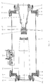
- a cylindrical tube housing 10 carries at both ends a flange strip 11, 12, to which a holding plate 15, 16 is fastened by means of screws 13, 14, each of which has an opening 17, 18.
- an insulating housing 19 of a commercially available SF 6 switchgear installation end closure is fastened, the inner parts of which are not shown in FIG. 1, but which are from the prospectus of ABB Energy Stamm GmbH, page 7 mentioned above, left, or from the prospectus of ABB Jardin und Draht GmbH, Mannheim, publication no. K + D 1048 / 3D (4.88 / 1) 04, Low pressure oil cable ", on page 6, shown on the left.
- the tubular housing 10 also has a burst protection device 30.
- the cable end closure with the insulating housing 19, 20 is first produced, as can be seen from the above-mentioned brochures or publications. Then there are several options: On the one hand, a plate 15 can be connected to the flange 19a of the insulating housing 19/20. The tube housing 10 is then fastened to the plate 15 with the screw connections 13. Then the other plate 16 is screwed onto the tubular housing 10 with the screw connections 14 and finally the insulating body 25 is fastened to the plate 16 via the flange 24 and the screw connections 26, the extension 27 being inserted into the interior of the cylinder contact piece 21.
- the plate 15, the Pipe housing 10 and the plate 16 form a preassembled unit
- the pre-assembled unit from the tubular housing 10, the plate 16 and the insulating body 25 attached thereto which according to Installation of the cable end closure within the insulating housing 19/20 on the Plate 15 can be attached.
- the insulating body 25 for a cable connector is significantly shorter than the cable section within the oil-filled housing of the known Cable sleeve.
- the inside of the tube housing 10 is filled with SF 6 gas as an insulating agent.
- FIG 3 shows a first embodiment of a three-phase arrangement of a cable sleeve.
- the cable sleeve has a tubular housing 40, which consists of two cup-shaped Housing parts 41 and 42 assembled by means of a flange 43 is.
- the pot bottom 44 and 45 of the two housing parts 41 and 42 is in one piece connected to the pipe sections 41a and 41b.
- the pot bases 44 and 45 have a number of openings 46 and corresponding to the number of phases 47.
- Three cable terminations 48 and 49 are inserted into the openings 46 (in Fig. 3, the third cable end closure is not shown), the attachment of the Cable end closure 48 and 49 made on the pot bottom 44 in the same way becomes like attaching the cable end closure to the insulating housing 19/20 on the plate 15 of the embodiment according to FIG. 1.
- insulating body 50 Through the openings 47 of the other pan bottom 45 insulating body 50 are one Inserted cable connector, which correspond to the insulating body 25 of FIG. 1 or the same.
- the electrically conductive connection of the insulating body 50 to the cable termination 48 is carried out in the same way as the electrically conductive connection of the corresponding parts of Fig. 1st
- a cable connector 51 is drawn inserted; this cable connector is of course also in the insulating body 25 in the embodiment according to FIG. 1 plugged in.
- the cable end closure with the insulating housing 19/20 designed as shown in FIG. 3.
- the insulating housing is in a Way, as described in the above-mentioned documents, a corresponding Cable assembly 52 inserted.
- housing 40 consists of two housing parts 41 and 42 is composed.
- housing 40 in this way form like the tube housing 10.
- the pot bottoms 44 and 45 with the three openings 46 and 47 are formed by a plate which in the same way as the plates 15, 16 by means of the flange rings 11, 12 on the one-piece tube housing 40 are mounted.
- the advantages of single-pole 1 are also in the three-pole version 3 available: The assembly of the arrangement is simple and the length the cable sleeve is also 25% opposite in the three-pole version the known arrangement reduced.
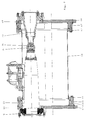
- FIG. 2 shows a further embodiment of a cable sleeve according to the invention Similar to that of FIG. 1, only in a three-pole version.
- a tube housing 60 is provided at both ends with a flange 61, 62.
- On the flange 61 is with the interposition of a ring cylinder 63rd a cover plate 64 fastened by means of screw connections 65, which cover plate 64 a number of openings 66 corresponding to the number of phases has, through which a cable end closure 19, 20 is passed; the cable end closure 3 has the reference numerals 48 and 49.
- each cable end closure is 19/20, in the same way as the 1 provided with the cylindrical contact piece 21, which is formed in the same way as that of FIG. 1 or FIG. 3.
- a cover plate 68 is attached, which also corresponds to the number of phases Number of openings 69, which from the insulating housing 70th is penetrated, which insulating housing attached to the outside of the cover plate 68 is.
- the insulating housing 70 corresponds to the insulating housing 25 of FIGS. 1 and has at its inner end a cylindrical extension 71 which, like the cylindrical one Extension 27 engages in the interior of the cylindrical contact piece.
- the interior is the same as in the embodiment according to FIGS. 1 and 3 of the tube housing 60 filled with insulating gas and the advantages of the single-phase encapsulated Arrangement is also present in the three-phase encapsulated arrangement: the considerably simplified assembly method and a significantly shortened design compared to the known arrangements is shortened by approximately 25%.
Landscapes
- Cable Accessories (AREA)
Applications Claiming Priority (2)
| Application Number | Priority Date | Filing Date | Title |
|---|---|---|---|
| DE1998105068 DE19805068A1 (de) | 1998-02-10 | 1998-02-10 | Kabelmuffe |
| DE19805068 | 1998-02-10 |
Publications (3)
| Publication Number | Publication Date |
|---|---|
| EP0936715A2 true EP0936715A2 (fr) | 1999-08-18 |
| EP0936715A3 EP0936715A3 (fr) | 2001-05-02 |
| EP0936715B1 EP0936715B1 (fr) | 2006-08-30 |
Family
ID=7857064
Family Applications (1)
| Application Number | Title | Priority Date | Filing Date |
|---|---|---|---|
| EP19980123883 Expired - Lifetime EP0936715B1 (fr) | 1998-02-10 | 1998-12-16 | Manchon de câble |
Country Status (2)
| Country | Link |
|---|---|
| EP (1) | EP0936715B1 (fr) |
| DE (2) | DE19805068A1 (fr) |
Cited By (1)
| Publication number | Priority date | Publication date | Assignee | Title |
|---|---|---|---|---|
| WO2017029627A1 (fr) * | 2015-08-18 | 2017-02-23 | Chan Lin Fong | Joint de transition |
Families Citing this family (1)
| Publication number | Priority date | Publication date | Assignee | Title |
|---|---|---|---|---|
| DE10341302B3 (de) * | 2003-09-02 | 2005-02-17 | Siemens Ag | Druckgasisolierter Kabelanschlussbaustein |
Family Cites Families (13)
| Publication number | Priority date | Publication date | Assignee | Title |
|---|---|---|---|---|
| US3876820A (en) * | 1974-02-01 | 1975-04-08 | Detroit Edison Co | Pressurized fluid insulation for high voltage cable |
| DE2733815C2 (de) * | 1977-07-27 | 1982-05-27 | Felten & Guilleaume Carlswerk AG, 5000 Köln | Übergangsmuffe |
| DE7822838U1 (de) * | 1978-07-29 | 1978-11-09 | Felten & Guilleaume Carlswerk Ag, 5000 Koeln | Steckverbinder zum Verbinden von zwei Kabelenden |
| DE3822288A1 (de) * | 1988-07-01 | 1990-01-04 | Felten & Guilleaume Energie | Verbindungsmuffe fuer vpe-isolierte hoechstspannungskabel |
| NL8901138A (nl) * | 1989-05-03 | 1990-12-03 | Nkf Kabel Bv | Insteekverbinding voor hoogspanningskunststofkabels. |
| DE4009358C2 (de) * | 1990-03-23 | 1997-05-15 | Sachsenwerk Ag | Steckbuchse |
| FR2670627B1 (fr) * | 1990-12-18 | 1993-02-12 | Alsthom Gec | Agencement de fond d'enveloppe d'appareillage a haute tension sous enveloppe metallique a isolation gazeuse en particulier pour raccordement de cable. |
| DE4122001C2 (de) * | 1991-07-03 | 1998-01-29 | Felten & Guilleaume Energie | Mit SF¶6¶-Gas gefüllte Verbindungsmuffe für VPE-isolierte Höchstspannungskabel |
| DE4139100C1 (en) * | 1991-11-28 | 1993-01-07 | Karl Pfisterer Elektrotechnische Spezialartikel Gmbh & Co Kg, 7000 Stuttgart, De | Plug and socket appts. - has elastic deformable damping piece(s) radially tensioned against contact support as well as socket when coupled together |
| DE4318074A1 (de) * | 1993-06-01 | 1994-12-08 | Abb Patent Gmbh | Gekapselte gasisolierte Schaltanlage mit Kabelendverschluß |
| DE4403571C1 (de) * | 1994-02-05 | 1995-05-18 | Pfisterer Elektrotech Karl | Verbindungsmuffe für kunststoffisolierte Hochspannungsenergieversorgungskabel |
| DE19508973C2 (de) * | 1995-03-13 | 2002-04-04 | Abb Patent Gmbh | Kabelgarnitur mit einem ein Kabel hülsenartig umschließenden Druckschieber |
| DE19508975A1 (de) * | 1995-03-13 | 1996-09-19 | Abb Patent Gmbh | Vorrichtung zur Ausübung eines Druckes auf einen elastischen Feldsteuerkonus |
-
1998
- 1998-02-10 DE DE1998105068 patent/DE19805068A1/de not_active Ceased
- 1998-12-16 EP EP19980123883 patent/EP0936715B1/fr not_active Expired - Lifetime
- 1998-12-16 DE DE59813702T patent/DE59813702D1/de not_active Expired - Lifetime
Cited By (1)
| Publication number | Priority date | Publication date | Assignee | Title |
|---|---|---|---|---|
| WO2017029627A1 (fr) * | 2015-08-18 | 2017-02-23 | Chan Lin Fong | Joint de transition |
Also Published As
| Publication number | Publication date |
|---|---|
| DE59813702D1 (de) | 2006-10-12 |
| EP0936715A3 (fr) | 2001-05-02 |
| EP0936715B1 (fr) | 2006-08-30 |
| DE19805068A1 (de) | 1999-08-12 |
Similar Documents
| Publication | Publication Date | Title |
|---|---|---|
| DE19519301A1 (de) | Trenner für eine metallgekapselte gasisolierte Hochspannungsschaltanlage | |
| DE4412784A1 (de) | Strom- und Spannungssensor für ein Hochspannungsschaltfeld und Hochspannungsschaltfeld mit einem solchen Strom- und Spannungssensor | |
| DE2924430A1 (de) | Metallgekapselte, sf tief 6 -gasisolierte schaltanlage | |
| DE3313192A1 (de) | Gekapselte, gasisolierte mittelspannungsschaltanlage | |
| WO2000045486A1 (fr) | Dispositif disjoncteur haute tension encapsule pour courant polyphase pour montage a l'exterieur | |
| EP1249910B1 (fr) | Disjoncteur haute-tension pour une installation de commutation à isolation gaseuse | |
| WO1998008284A1 (fr) | Installation a haute tension isolee par gas, encapsulee et pourvue d'un composant de connexion cloisonne | |
| DE3521945A1 (de) | Trennschalter fuer eine metallgekapselte, druckgasisolierte hochspannungsschaltanlage | |
| DE19641391C1 (de) | Hochspannungsschaltanlage in Hybridbauweise | |
| EP0875971B1 (fr) | Installation de distribution électrique pour haute tension | |
| EP0936715B1 (fr) | Manchon de câble | |
| EP1943707A1 (fr) | Disjoncteur de coupure en charge haute tension et configuration d'interrupteur | |
| DE4438776C1 (de) | Metallgekapselte elektrische Hochspannungsschaltanlage mit einem Leistungsschalter | |
| DE19845006C1 (de) | Oberirdische Kabelverbindung | |
| DE3318229A1 (de) | Gehaeuse fuer hochspannungsschalter | |
| EP0718942B1 (fr) | Installation à haute tension | |
| DE102016207292A1 (de) | Elektrische Schutzvorrichtung | |
| DE10341302B3 (de) | Druckgasisolierter Kabelanschlussbaustein | |
| DE19530163C2 (de) | Hochspannungsausleitungs- und -durchführungsanordnung für Transformatoren oder Drosselspulen | |
| DE1170501C2 (de) | Metallgekapselte Hochspannungsschaltanlage | |
| DE102006001237A1 (de) | Gasisolierte, dreiphasige gekapselte Schaltanlage | |
| DE2847376C2 (de) | Ein- oder mehrpolige Trennschalteranordnung für gekapselte Schaltanlagen | |
| DE102010004971A1 (de) | Vorrichtung für eine Schaltanlage | |
| EP1691388B1 (fr) | Connecteur enfichable | |
| DE544910C (de) | Elektrischer Messwandler mit an einem oder beiden Enden liegenden, von einem einteiligen Wandlerisoliergehaeuse getragenen Armaturen fuer die Primaeranschluesse |
Legal Events
| Date | Code | Title | Description |
|---|---|---|---|
| PUAI | Public reference made under article 153(3) epc to a published international application that has entered the european phase |
Free format text: ORIGINAL CODE: 0009012 |
|
| AK | Designated contracting states |
Kind code of ref document: A2 Designated state(s): BE CH DE FR GB IT LI NL SE |
|
| AX | Request for extension of the european patent |
Free format text: AL;LT;LV;MK;RO;SI |
|
| PUAL | Search report despatched |
Free format text: ORIGINAL CODE: 0009013 |
|
| AK | Designated contracting states |
Kind code of ref document: A3 Designated state(s): AT BE CH CY DE DK ES FI FR GB GR IE IT LI LU MC NL PT SE |
|
| AX | Request for extension of the european patent |
Free format text: AL;LT;LV;MK;RO;SI |
|
| 17P | Request for examination filed |
Effective date: 20010627 |
|
| RAP1 | Party data changed (applicant data changed or rights of an application transferred) |
Owner name: ABB PATENT GMBH |
|
| AKX | Designation fees paid |
Free format text: BE CH DE FR GB IT LI NL SE |
|
| GRAP | Despatch of communication of intention to grant a patent |
Free format text: ORIGINAL CODE: EPIDOSNIGR1 |
|
| GRAS | Grant fee paid |
Free format text: ORIGINAL CODE: EPIDOSNIGR3 |
|
| GRAA | (expected) grant |
Free format text: ORIGINAL CODE: 0009210 |
|
| AK | Designated contracting states |
Kind code of ref document: B1 Designated state(s): BE CH DE FR GB IT LI NL SE |
|
| PG25 | Lapsed in a contracting state [announced via postgrant information from national office to epo] |
Ref country code: NL Free format text: LAPSE BECAUSE OF FAILURE TO SUBMIT A TRANSLATION OF THE DESCRIPTION OR TO PAY THE FEE WITHIN THE PRESCRIBED TIME-LIMIT Effective date: 20060830 |
|
| REG | Reference to a national code |
Ref country code: GB Ref legal event code: FG4D Free format text: NOT ENGLISH |
|
| REG | Reference to a national code |
Ref country code: CH Ref legal event code: EP |
|
| REF | Corresponds to: |
Ref document number: 59813702 Country of ref document: DE Date of ref document: 20061012 Kind code of ref document: P |
|
| GBT | Gb: translation of ep patent filed (gb section 77(6)(a)/1977) |
Effective date: 20061004 |
|
| PG25 | Lapsed in a contracting state [announced via postgrant information from national office to epo] |
Ref country code: SE Free format text: LAPSE BECAUSE OF FAILURE TO SUBMIT A TRANSLATION OF THE DESCRIPTION OR TO PAY THE FEE WITHIN THE PRESCRIBED TIME-LIMIT Effective date: 20061130 |
|
| PG25 | Lapsed in a contracting state [announced via postgrant information from national office to epo] |
Ref country code: BE Free format text: LAPSE BECAUSE OF NON-PAYMENT OF DUE FEES Effective date: 20061231 |
|
| NLV1 | Nl: lapsed or annulled due to failure to fulfill the requirements of art. 29p and 29m of the patents act | ||
| PLBE | No opposition filed within time limit |
Free format text: ORIGINAL CODE: 0009261 |
|
| STAA | Information on the status of an ep patent application or granted ep patent |
Free format text: STATUS: NO OPPOSITION FILED WITHIN TIME LIMIT |
|
| 26N | No opposition filed |
Effective date: 20070531 |
|
| BERE | Be: lapsed |
Owner name: ABB PATENT G.M.B.H. Effective date: 20061231 |
|
| REG | Reference to a national code |
Ref country code: GB Ref legal event code: 732E Free format text: REGISTERED BETWEEN 20101216 AND 20101222 |
|
| REG | Reference to a national code |
Ref country code: FR Ref legal event code: TP |
|
| REG | Reference to a national code |
Ref country code: FR Ref legal event code: PLFP Year of fee payment: 18 |
|
| REG | Reference to a national code |
Ref country code: FR Ref legal event code: PLFP Year of fee payment: 19 |
|
| REG | Reference to a national code |
Ref country code: DE Ref legal event code: R082 Ref document number: 59813702 Country of ref document: DE Representative=s name: REBLE KLOSE SCHMITT PARTNERSCHAFTSGESELLSCHAFT, DE |
|
| REG | Reference to a national code |
Ref country code: FR Ref legal event code: PLFP Year of fee payment: 20 |
|
| PGFP | Annual fee paid to national office [announced via postgrant information from national office to epo] |
Ref country code: FR Payment date: 20171219 Year of fee payment: 20 |
|
| PGFP | Annual fee paid to national office [announced via postgrant information from national office to epo] |
Ref country code: CH Payment date: 20171221 Year of fee payment: 20 Ref country code: GB Payment date: 20171221 Year of fee payment: 20 Ref country code: IT Payment date: 20171218 Year of fee payment: 20 |
|
| PGFP | Annual fee paid to national office [announced via postgrant information from national office to epo] |
Ref country code: DE Payment date: 20171231 Year of fee payment: 20 |
|
| REG | Reference to a national code |
Ref country code: DE Ref legal event code: R071 Ref document number: 59813702 Country of ref document: DE |
|
| REG | Reference to a national code |
Ref country code: CH Ref legal event code: PL |
|
| REG | Reference to a national code |
Ref country code: GB Ref legal event code: PE20 Expiry date: 20181215 |
|
| PG25 | Lapsed in a contracting state [announced via postgrant information from national office to epo] |
Ref country code: GB Free format text: LAPSE BECAUSE OF EXPIRATION OF PROTECTION Effective date: 20181215 |