EP0936717A2 - Elektrischer Schalteinrichtung mit Verriegelung für erste und zweite Auslösebedingungen - Google Patents
Elektrischer Schalteinrichtung mit Verriegelung für erste und zweite Auslösebedingungen Download PDFInfo
- Publication number
- EP0936717A2 EP0936717A2 EP99101767A EP99101767A EP0936717A2 EP 0936717 A2 EP0936717 A2 EP 0936717A2 EP 99101767 A EP99101767 A EP 99101767A EP 99101767 A EP99101767 A EP 99101767A EP 0936717 A2 EP0936717 A2 EP 0936717A2
- Authority
- EP
- European Patent Office
- Prior art keywords
- current
- trip
- magnitude
- ground
- interlock signal
- Prior art date
- Legal status (The legal status is an assumption and is not a legal conclusion. Google has not performed a legal analysis and makes no representation as to the accuracy of the status listed.)
- Granted
Links
- 230000006870 function Effects 0.000 title claims abstract description 101
- 238000011144 upstream manufacturing Methods 0.000 claims abstract description 34
- 230000004044 response Effects 0.000 claims abstract description 20
- 230000007246 mechanism Effects 0.000 abstract description 17
- 238000010586 diagram Methods 0.000 description 6
- 230000000977 initiatory effect Effects 0.000 description 3
- 238000012545 processing Methods 0.000 description 2
- 230000001681 protective effect Effects 0.000 description 2
- 238000005070 sampling Methods 0.000 description 2
- 101100449067 Neurospora crassa (strain ATCC 24698 / 74-OR23-1A / CBS 708.71 / DSM 1257 / FGSC 987) cbs-2 gene Proteins 0.000 description 1
- 239000003990 capacitor Substances 0.000 description 1
- 230000003111 delayed effect Effects 0.000 description 1
- 238000011156 evaluation Methods 0.000 description 1
- 230000006872 improvement Effects 0.000 description 1
- 238000009434 installation Methods 0.000 description 1
- 238000000034 method Methods 0.000 description 1
- 238000012986 modification Methods 0.000 description 1
- 230000004048 modification Effects 0.000 description 1
- 230000007935 neutral effect Effects 0.000 description 1
- 230000000737 periodic effect Effects 0.000 description 1
- 239000007858 starting material Substances 0.000 description 1
- 238000012360 testing method Methods 0.000 description 1
Images

Classifications
-
- H—ELECTRICITY
- H02—GENERATION; CONVERSION OR DISTRIBUTION OF ELECTRIC POWER
- H02H—EMERGENCY PROTECTIVE CIRCUIT ARRANGEMENTS
- H02H7/00—Emergency protective circuit arrangements specially adapted for specific types of electric machines or apparatus or for sectionalised protection of cable or line systems, and effecting automatic switching in the event of an undesired change from normal working conditions
- H02H7/26—Sectionalised protection of cable or line systems, e.g. for disconnecting a section on which a short-circuit, earth fault, or arc discharge has occured
- H02H7/30—Staggered disconnection
-
- H—ELECTRICITY
- H02—GENERATION; CONVERSION OR DISTRIBUTION OF ELECTRIC POWER
- H02H—EMERGENCY PROTECTIVE CIRCUIT ARRANGEMENTS
- H02H7/00—Emergency protective circuit arrangements specially adapted for specific types of electric machines or apparatus or for sectionalised protection of cable or line systems, and effecting automatic switching in the event of an undesired change from normal working conditions
- H02H7/26—Sectionalised protection of cable or line systems, e.g. for disconnecting a section on which a short-circuit, earth fault, or arc discharge has occured
- H02H7/261—Sectionalised protection of cable or line systems, e.g. for disconnecting a section on which a short-circuit, earth fault, or arc discharge has occured involving signal transmission between at least two stations
- H02H7/262—Sectionalised protection of cable or line systems, e.g. for disconnecting a section on which a short-circuit, earth fault, or arc discharge has occured involving signal transmission between at least two stations involving transmissions of switching or blocking orders
-
- H—ELECTRICITY
- H02—GENERATION; CONVERSION OR DISTRIBUTION OF ELECTRIC POWER
- H02H—EMERGENCY PROTECTIVE CIRCUIT ARRANGEMENTS
- H02H1/00—Details of emergency protective circuit arrangements
- H02H1/0038—Details of emergency protective circuit arrangements concerning the connection of the detecting means, e.g. for reducing their number
-
- H—ELECTRICITY
- H02—GENERATION; CONVERSION OR DISTRIBUTION OF ELECTRIC POWER
- H02H—EMERGENCY PROTECTIVE CIRCUIT ARRANGEMENTS
- H02H1/00—Details of emergency protective circuit arrangements
- H02H1/0061—Details of emergency protective circuit arrangements concerning transmission of signals
Definitions
- This invention is directed to a electrical switching apparatus and, more particularly, to a circuit interrupter, such as a circuit breaker, including interlocks with another circuit breaker.
- Circuit switching apparatus include, for example, circuit switching devices and circuit interrupters such as circuit breakers, contactors, motor starters, motor controllers and other load controllers.
- Circuit breakers are generally old and well known in the art. Examples of circuit breakers are disclosed in U.S. Patent Nos. 4,751,606; and 5,341,191. Such circuit breakers are used to protect electrical circuitry from damage due to a overcurrent condition, such as an overload condition or a relatively high level short circuit or fault condition.
- Molded case circuit breakers include a pair of separable contacts per phase which may be operated either manually by way of a handle disposed on the outside of the case or automatically in response to an overcurrent condition.
- circuit breakers include a operating mechanism, which is designed to rapidly open and close the separable contacts, and a trip mechanism, which senses overcurrent conditions in an automatic mode of operation. Upon sensing an overcurrent condition, the trip mechanism trips the operating mechanism to a trip state which moves the separable contacts to their open position.
- a time-trip curve of the desired current response characteristics of the circuit interrupter over time may be employed.
- the current factor is shown on the horizontal axis and the time factor is shown on the vertical axis.
- the time-trip curve includes various types of overcurrent trip conditions, such as a long delay trip, a short delay trip, a instantaneous trip, or a ground fault trip.
- Modem trip mechanisms often employ a microprocessor to detect these overcurrent trip conditions.
- the long delay protection feature generally follows an I 2 t sloped portion of the log-log time-trip curve.
- the long delay feature is sometimes referred to as a thermal trip feature since it most closely resembles a thermal-type tripping operation typically offered by predecessor non-electronic circuit interrupters.
- This feature consists of both a selectable long delay current pickup factor (e.g ., LDPU factor) and a long delay time factor (e . g ., LDT factor).
- the LDPU factor selectively adjusts the time-trip curve along the horizontal or current axis and the LDT factor selectively adjusts the time-trip curve along the vertical or time axis.
- the limits of the long delay protection feature provide a first trip-curve portion which is adjustable in both axes.
- the long delay protection feature provides a I 2 t trip characteristic for currents exceeding the LDPU factor wherein, at higher levels of current in excess of the LDPU factor, a shorter LDT will result, although other trip characteristics such as I 4 t may be employed.
- the circuit interrupter provide a more rapid response than that provided by the long delay protection feature.
- This more rapid response is commonly referred to as a short delay protection feature and is characterized by a portion of the trip-curve designated as the short delay trip-curve portion.
- the short delay protection feature may be selectively configured in various manners such as a fixed time response or an I 2 t response.
- the current level at which a short delay trip condition is initiated is commonly referred to as a short delay pickup factor (e.g. , SDPU factor).
- SDPU factor The current level at which a short delay trip condition is initiated.
- Other conditions utilize a fixed time short delay trip-curve portion and still other conditions arise where it is necessary to impose an I 2 t trip characteristic trip curve portion.
- the next level of protection offered by the circuit interrupter is a instantaneous trip-curve portion which corresponds to an instantaneous protection feature.
- a trip condition as rapidly as possible (e.g., within 20 milliseconds or less of sensing the faulted condition).
- This overcurrent level is selectively adjustable within the instantaneous trip-curve portion of the time-trip curve.
- ground fault protection feature provides the same types of protection as does the short delay protection feature, although the ground fault pick-up level is more sensitive than the short delay pick-up level.
- the ground fault protection feature provides that, should a certain level of current be flowing through a ground path associated with the electrical circuit in excess of a ground fault pickup factor (e.g., a GFPU factor), a ground fault trip condition is initiated.
- a ground fault pickup factor e.g., a GFPU factor
- the GFPU factor is selectively adjustable in a ground fault trip-curve which typically employs a fixed time or I 2 t ground fault protection. Under certain conditions, it is necessary to wait a selectively adjustable period of time, designated as the ground fault time factor (e.g., GFT factor), before initiating a ground fault trip condition.
- GFT factor ground fault time factor
- a main bus provides power to a number of additional buses which, in turn, energize a plurality of distribution circuits.
- power transformers step down the voltage at various points in the distribution system.
- overcurrent protection devices are provided in the main bus and in at least some, if not all, of the other branches of the distribution system.
- Each of the overcurrent protection devices has its own overcurrent/time trip characteristic for responding to faults in the distribution system.
- these overcurrent/time trip characteristics of the various overcurrent protection devices are coordinated through a hierarchical arrangement in order that only the closest protection device above the fault trips to minimize the interruption to service in the distribution system.
- zone interlocks between the overcurrent protection devices are employed.
- a lower order overcurrent protective device of the hierarchy sees an overload current, it sends an interlock signal to the next higher order device to block generation of a trip signal by the latter and to give the former time to react.
- This permits adjacent overcurrent protective devices in the hierarchy to have their overcurrent/time trip characteristics set closer together, while assuring that the lower order device will trip first if conditions warrant.
- U.S. Patent No. 4,827,369 discloses the use of zone interlocks between upstream and downstream circuit interrupters to adjust the timing of short delay and ground fault protection in the upstream devices. If a short delay current threshold is exceeded in the downstream device, it sends a short delay zone interlock signal to the upstream device to indicate that a short delay fault condition has been identified. If the short delay current threshold is exceeded in the upstream device, and the short delay zone interlock signal is not received from the downstream device, then a short delay trip is rapidly initiated by the upstream device on the second consecutive recognition of that threshold being exceeded (e.g ., to prevent the occurrence of a false initiation of the short delay trip condition resulting from a possible late signal from a downstream device due to possible asynchronous conditions).
- a time delayed portion e.g., either an I 2 t or fixed time type
- the short delay routine is executed by the upstream device.
- ground fault protection is implemented in a similar manner as the short delay protection, with each of the upstream and downstream devices inputting an input ground fault zone interlock signal and outputting an output ground fault zone interlock signal.
- two separate input interlock signals indicate whether respective ground fault and short delay conditions were identified by a downstream circuit interrupter
- two separate output interlock signals indicate to an upstream circuit interrupter whether respective ground fault and short delay conditions were identified by the intermediate circuit interrupter.
- the apparatus advantageously employs a single interlock interface for both first and second trip functions, such as ground fault protection and short delay protection.
- the apparatus inputs a single interlock signal for both trip functions from a downstream electrical switching device, and outputs a single interlock signal for these trip functions to an upstream electrical switching device. In this manner, wiring between the adjacent electrical switching devices is reduced.
- the trip means of the apparatus has means for generating a first trip function of electrical current and time, and means for generating a second trip function of electrical current and time.
- a means inputs a first interlock signal from the downstream electrical switching device.
- a means generates and outputs a second interlock signal to the upstream electrical switching device in response to both the first and second trip functions.
- a means selectively trips the operating means as a function of the first interlock signal, the first trip function, and the second trip function.
- an electrical switching apparatus comprises separable contact means for movement between a closed position and a open position.
- An operating means moves the separable contact means between the closed position and the open position thereof and has a first state and a second state which corresponds to the open position of the separable contact means.
- a means senses electrical current flowing through the separable contact means as a sensed current.
- a trip means employs the sensed current for tripping the operating means to the second state thereof to move the separable contact means to the open position thereof.
- the trip means includes means for generating a first trip function of electrical current and time, and means for generating a second trip function of electrical current and time.
- a means inputs the first interlock signal from a downstream electrical switching device which has means for generating the first interlock signal with a first value when current through the downstream device exceeds a predetermined value and with a second value otherwise.
- a means generates and outputs a second interlock signal to an upstream electrical switching device in response to both of the first and second trip functions.
- a means selectively trips the operating means as a function of the first interlock signal, the first trip function, and the second trip function.
- the electrical current includes a ground current and a phase current
- the means for sensing includes means for sensing the ground current as a sensed ground current, and means for sensing the phase current as a sensed phase current.
- the means for generating the first trip function employs the sensed ground current to generate the first trip function as a ground fault trip function
- the means for generating the second trip function employs the sensed phase current to generate the second trip function as a short delay trip function.
- the electrical current includes at least one of a ground fault current and a phase fault current.
- the ground fault trip function employs a ground fault magnitude of electrical current and a first time period
- the short delay trip function employs a short delay magnitude of electrical current and a second time period.
- the means for generating and outputting the second interlock signal includes means for asserting that signal: (a) when the ground fault current exceeds the ground fault magnitude, or (b) when the phase fault current exceeds the short delay fault magnitude.
- a circuit breaker comprises separable contact means for movement between a closed position and an open position.
- An operating means moves the separable contact means between the closed position and the open position thereof and has a first state and a second state which corresponds to the open position of the separable contact means.
- a means senses electrical current flowing through the separable contact means as a sensed current.
- a trip means employs the sensed current for tripping the operating means to the second state thereof to move the separable contact means to the open position thereof.
- the trip means includes means for generating a first trip function employing a first magnitude of electrical current and a first time period, and means for generating a second trip function employing a second magnitude of electrical current and a second time period.
- a means inputs the first interlock signal from a downstream electrical switching device which has means for generating the first interlock signal with a first value when current through the downstream device exceeds a predetermined value and with a second value otherwise.
- a means generates and outputs a second interlock signal to an upstream electrical switching device in response to both of the first and second trip functions.
- a means selectively trips the operating means, when the first interlock signal has the first value, as a function of the first magnitude and the first time period of the first trip function, and as a function of the second magnitude and the second time period of the second trip function.
- a means selectively trips the operating means, when the first interlock signal has the second value, as a function of the first magnitude of the first trip function or the second magnitude of the second trip function.
- a system of electrical switching apparatus comprises a first electrical switching apparatus and at least one second electrical switching apparatus.
- Each of the electrical switching apparatus comprises separable contact means for movement between a closed position and an open position, operating means for moving the separable contact means between the closed position and the open position thereof having a first state and a second state which corresponds to the open position of the separable contact means, means for sensing electrical current flowing through the separable contact means as a sensed current, and trip means employing the sensed current for tripping the operating means to the second state thereof to move the separable contact means to the open position thereof.
- the trip means includes means for generating a first trip function of electrical current and time, and means for generating a second trip function of electrical current and time.
- the trip means of a downstream one of the first and second electrical switching apparatus further includes means for generating a first interlock signal with a first value when current through the downstream one of the electrical switching apparatus exceeds a predetermined value and with a second value otherwise.
- the trip means of an upstream one of the first and second electrical switching apparatus further includes means for inputting the first interlock signal from the downstream one of the first and second electrical switching apparatus.
- a means selectively trips the operating means of the upstream one of the first and second electrical switching apparatus as a function of the first interlock signal of the downstream one of the first and second electrical switching apparatus, and both of the first and second trip functions of the upstream one of the first and second electrical switching apparatus.
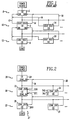
- FIG. 1 is a block diagram of an intermediate circuit breaker (CB) 2 interfacing an upstream circuit breaker (CB) 4 and a downstream circuit breaker (CB) 6 including separate interlock interfaces for ground fault protection and short delay protection.
- Zone interlocks are employed to provide coordination among three levels 8, 10, 12 of circuit breakers in the hierarchy.
- the trip units (not shown) of CBs 2 and 14 generate zone interlock signals (e.g ., SOUT or GOUT) when they see a fault.
- These output zone interlock signals are transmitted to an input zone interlock signal (e.g. , SIN or GIN, respectively) of the trip unit (not shown) of CB 4 above them in the hierarchy through leads 16,18 and 17,19, respectively.
- zone interlock signals prevent tripping of CB 4, giving CB 2 or 14 time to respond to a fault below it.
- This zone interlock scheme also allows the protection curves for the trip units (not shown) of the lower CBs 6 and 20 to be closer to the protection curve for the trip unit of CB 2.
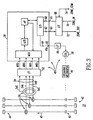
- FIG. 2 is a block diagram of a intermediate circuit breaker (CB) 22 interfacing an upstream circuit breaker (CB) 24 and a downstream circuit breaker (CB) 26 including a single interlock interface for ground fault protection and short delay protection.
- CBs 24,22,26 form a system 27 of circuit breakers.
- Zone interlocks are employed to provide coordination among three levels 28,30,32 of circuit breakers in the hierarchy. For example, at level 30, the trip units (not shown) of CBs 22 and 34 each generate a zone interlock signal ( i . e ., ZONE_OUT) when they see a fault. These output zone interlock signals are transmitted to an input zone interlock signal ( i . e .
- the zone interlock signals prevent tripping of CB 24, giving CB 22 or 34 time to respond to a fault below it.
- This zone interlock scheme also allows the protection curves for the trip units (not shown) of the lower CBs 26 and 39 to be closer to the protection curve for the trip unit of CB 22.
- Zone interlocking is provided on both phase and ground protection, if enabled.
- the ground and short delay interlocking functions are combined on one common set of connections (e.g ., 36,38). In this manner, wiring between the adjacent CBs 22-24 and 34-24 is reduced.
- GOUT ground fault interlock
- SOUT short delay interlock
- ZONE_OUT ground fault/short delay interlock
- the zone interlock output signal ZONE_OUT is enabled when the fault: (1) exceeds the ground setting; or (2) is greater than two times the rated current value of the electrical current of the CB 22.
- the trip unit (not shown) of downstream CB 26 includes a circuit for generating the zone interlock output signal ZONE_OUT at interlock output terminal 26O with an exemplary true value, when current through the downstream CB 26 exceeds a predetermined value, and with an exemplary false value otherwise.
- the trip unit (not shown) of intermediate CB 22 includes a circuit for inputting zone interlock input signal ZONE_IN at interlock input terminal 22I from downstream CB 26.
- This trip unit also includes a circuit for selectively tripping the operating mechanism 46 (as shown in Figure 3) of CB 22 as a function of the zone interlock output signal ZONE_OUT of downstream CB 26, and the ground fault and short delay trip functions of CB 22.
- the trip unit (not shown in Figure 2) of intermediate CB 22 inputs the zone interlock input signal ZONE_IN from the ZONE_OUT signal of downstream CB 26.
- the CB 22 generates and outputs at terminal 22O the zone interlock output signal ZONE_OUT to upstream CB 24 in response to both of the ground fault and short delay trip functions of the intermediate CB 22.
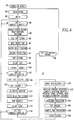
- FIG. 3 is a functional block diagram of intermediate CB 22 of Figure 2.
- the circuit breaker 22 includes one or more separable contacts 40 electrically interconnected between line terminals 42 and load terminals 44 for movement between a closed position (not shown) and an open position (as shown in Figure 3) in order to switch one or more electrical currents, such as current 45, flowing through the separable contacts 40 between the terminals 42,44.
- the circuit breaker 22 also includes an operating mechanism 46 for moving the separable contacts 40 between the closed and open positions, and a trip circuit 48.
- the trip circuit 48 interfaces sensors, such as current transformers (CTs) 50, for sensing the line and ground electrical currents.
- CTs current transformers
- the trip circuit 48 includes a suitable interface (I/F) 52 for receiving the sensed current signals 54 from the CTs 50; a microcomputer 56, such as a SURE CHIP PLUS ; and a trip coil 58 controlled by the microcomputer 56.
- the sensed current signals 54 include a sensed ground current 54G and send phase currents 54A,54B,54C, which may represent both normal and fault currents in the electrical circuit.
- the microcomputer 56 employs a multiplexer (MUX) to select the seed current signals 54 from I/F 52; an analog-to-digital (A/D) converter to convert the analog current signals 54 to corresponding digital values; a microprocessor ( ⁇ P) to receive the digital values from the A/D; and a digital input/output circuit (I/O) to input various input signals, such as interlock input signal 60 at input port 61, and to output various output signals, such as interlock output signal 62 at output port 63 and trip signal 64 at output port 65.
- MUX multiplexer
- A/D analog-to-digital converter
- ⁇ P microprocessor
- I/O digital input/output circuit
- the operating mechanism 46 has a first state (e.g., closed) and a second state (e.g. , open or tripped) which corresponds to the open position of the separable contacts 40.
- the CTs 50 sense the electrical current, such as current 45, flowing through the separable contacts 40.
- the ⁇ P of the microcomputer 56 employs the digital values of the sensed current signals 54 from the A/D to generate the trip signal 64 at output 65 for tripping the operating mechanism 46 through interface (I/F) 66 and trip coil 58 to the tripped state to move the separable contacts 40 to the open position.
- the digital input/output circuit (I/O) for microcomputer 56 is interconnected with interface (I/F) 68 which inputs ZONE_IN signal 70 for presentation to the I/O at input port 61, and which outputs ZONE_OUT signal 72 from the I/O at output port 63.
- the ZONE_IN signal 70 and ZONE_OUT signal 72 are referenced to the ZONE_COM ground signal 74, which establishes a common ground for the interlock signals 70,72.
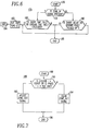
- an exemplary main loop routine 76 is executed by the ⁇ P of microcomputer 56 of Figure 3. After a power on reset at 78, initialization is conducted at 80. Next, at 82, the principal portion of routine 76 begins. At 84, a flag (FLG4) is tested to determine if four current samples are completed. If not, then step 84 is repeated. Otherwise, at 86, any data that needs written to nonvolatile random access memory (NVRAM) (not shown) is written at this time, switch settings (not shown) are read, and an auction8 routine auctioneers the highest sum of eight squared current values for the phases. Next, at 88 and 90, discrete and instantaneous protection routines, respectively, are executed.
- NVRAM nonvolatile random access memory
- the short delay routine 92 compares the highest sum of squared current values for the phases with the short delay setpoint and, if exceeded, a pickup occurs and a tally value is added to a short time tally (STALLY) value which is, in turn, compared with the short time setting and, if greater, a short flag is set - for eventual tripping.
- STALLY short time tally
- a trip routine is executed which generates the trip signal 64 at output 65 of Figure 3 in the event any trip conditions were detected at steps 88,90,92,94. Then, at 98, the flag (FLG4) tested at 84 is cleared before a deadman timer (not shown) for microcomputer 56 is updated at 100.
- a flag (FLG64) is tested to determine if 64 current samples are completed. If not, then step 84 is repeated. Otherwise, at 104, LEDs (not shown) are updated in order to provide LDPU or long delay, short delay, instantaneous and ground fault trip indicators (not shown) by driving a latch (not shown) external to the ⁇ P of microcomputer 56.
- a self calibration routine at 108, calculates calibration values for each phase and ground and stores these in NVRAM (not shown). The calibration procedure employs precision current sources (three phases and ground) and is automatically performed by the trip circuit 48.
- the initialization is repeated at 80. Otherwise, at 110 and 112, auction64 and long delay protection routines, respectively, are executed. These routines auctioneer the highest sum of 64 squared current values for the phases and use this value for long delay pickup and long time tally develop values.
- a trip routine is executed which generates the trip signal 64 at output 65 of Figure 3 in the event any trip flag conditions were detected at step 112. Then, at 116, the flag (FLG64) tested at 102 is cleared.
- a flag (FLG256) is tested to determine if 256 current samples are completed. If not, then step 84 is repeated. Otherwise, at 120, LEDs are updated as at 104. Then, at 122 and 124, refresh and over-temperature protection routines, respectively, are executed. These routines refresh key protection parameters such as switch settings, which correlate to the temperature of microcomputer 56; calibration values; and the internal diode voltage of microcomputer 56.
- a trip routine is executed which generates the trip signal 64 at output 65 of Figure 3 in the event any trip conditions were detected at step 124.
- a sample _ time evaluation routine is executed. This routine automatically selects the sampling interval for either a 50 Hz or 60 Hz sampling schedule. Then, at 130, the flag (FLG256) tested at 118 is cleared, after which step 84 is repeated.
- an exemplary interrupt routine 132 is executed by the ⁇ P of microcomputer 56 of Figure 3.
- a load_ptimer routine is executed at 136. This routine loads an internal timer of microcomputer 56 with a value per a predefined schedule that will provide the next time interrupt.
- the sensed current signals 54 from I/F 52 at MUX0-MUX3 of Figure 3 are sampled.
- miscellaneous routines are executed which read the interlock input signal 60 at input port 61 of Figure 3 to obtain the value of the ZONE_IN signal 70, and increment a counter (COUNT256) which has the count for the sample routine 138.
- a return from interrupt is executed at 172. Otherwise, at 144, the flag FLG4 is set.
- a thermal store routine is executed which reads a thermal memory capacitor (not shown) and digitally scales its value and stores it in memory.
- self calibration as discussed above in connection with step 106 of Figure 4
- five i . e ., three phase currents and one ground current, as shown in Figure 3, plus one neutral current (not shown)
- current samples are scaled at 150 before step 152 is executed.
- a counter COUNT8 is incremented (for use by units with a multiplexed display (not shown)) after which, at 170, a flag (BLINKFLG), which is used to control a status LED (not shown), is complemented. Finally, at 172, the return from interrupt (RTI) is executed.
- Figure 6 is flow chart of a routine 174 for processing the ZONE_IN signal 70 of Figure 3 which is read at step 140 of routine 132 of Figure 5.
- Routine 174 is part of the short delay routine 92 and ground protection routine 94 of Figure 4. After starting at 176, it is determined whether the ZONE_IN signal 70 is present at 178. If not, then it is determined whether a short delay fault or a ground fault is "picked up” at 180. The short delay fault and the ground fault are "picked up” in a manner similar to that set forth in Patent 4,752,853.
- step 180 employs a counter such that there must be two consecutive recognitions for these faults to be "picked up". In this manner, the possibility of a false trip initiation is reduced.
- the ZONE_IN signal 70 is present at 178, then at 182, if either the ground or the short delay fault pickup setting level has been exceeded, then it is determined whether a short time tally (STALLY) or a ground time tally (GTALLY) is exceeded. If so, then a trip is initiated at 183-184. Otherwise, the ZONE_IN interlock input signal 70 is disregarded if it is present at step 178 and neither the ground nor the short delay fault pickup setting level has been exceeded. In this manner, the trip circuit 48 of Figure 3 provides a normal time delay before tripping when the ZONE_IN interlock input signal 70 is present and the ground or short delay fault pickup seting level has been exceeded.
- STALLY short time tally
- GTALLY ground time tally
- the operating mechanism 46 is tripped either when the sensed ground current exceeds the ground fault pickup magnitude and the time period of the ground fault trip function is exceeded, or when the sensed phase current exceeds the short delay fault pickup magnitude and the time period of the short delay trip function is exceeded.
- the short time tally STALLY and ground time tally GTALLY are calculated and compared with predetermined short delay and ground fault limit settings, respectively, in a manner similar to that set forth in Patent 4,752,853.
- the highest squared current summation MAXI 2 is added to the short time tally STALLY.
- a constant such as 8PU 2
- the summation of the previous four ground current samples i.e., G4SUM
- G4SUM the ground time tally GTALLY.
- a constant such as 0.625PU 2
- Figure 7 is flow chart of a routine 186 for outputting the ZONE_OUT signal 72 through interlock output signal 62 at output port 63 and I/F 68 of Figure 3.
- G4SUM ground current samples
- MAXI 2 the highest squared current summation MAXI 2 is greater than twice the short delay pick up ( i.e. , SDPU) value
- the ZONE_OUT signal 72 is retracted by clearing the interlock output signal 62.
- an exemplary threshold of twice the short delay pick up (i . e ., SDPU) value is employed for the short delay response, it will be appreciated that a wide range of settings may be employed (e.g. , without limitation, the short delay pick up (i.e., SDPU) value and various multiples thereof).
- routine 186 ends at 196.
Landscapes
- Emergency Protection Circuit Devices (AREA)
- Keying Circuit Devices (AREA)
- Driving Mechanisms And Operating Circuits Of Arc-Extinguishing High-Tension Switches (AREA)
Applications Claiming Priority (2)
| Application Number | Priority Date | Filing Date | Title |
|---|---|---|---|
| US09/024,365 US5875088A (en) | 1998-02-17 | 1998-02-17 | Electrical switching apparatus employing interlocks for first and second trip functions |
| US24365 | 1998-02-17 |
Publications (3)
| Publication Number | Publication Date |
|---|---|
| EP0936717A2 true EP0936717A2 (de) | 1999-08-18 |
| EP0936717A3 EP0936717A3 (de) | 2000-05-10 |
| EP0936717B1 EP0936717B1 (de) | 2008-12-03 |
Family
ID=21820212
Family Applications (1)
| Application Number | Title | Priority Date | Filing Date |
|---|---|---|---|
| EP99101767A Expired - Lifetime EP0936717B1 (de) | 1998-02-17 | 1999-02-12 | Elektrische Schalteinrichtung mit Verriegelung für erste und zweite Auslösebedingungen |
Country Status (6)
| Country | Link |
|---|---|
| US (1) | US5875088A (de) |
| EP (1) | EP0936717B1 (de) |
| AU (1) | AU749406B2 (de) |
| BR (1) | BR9900413A (de) |
| CA (1) | CA2262199C (de) |
| DE (1) | DE69939997D1 (de) |
Families Citing this family (23)
| Publication number | Priority date | Publication date | Assignee | Title |
|---|---|---|---|---|
| US6330141B1 (en) * | 2000-06-13 | 2001-12-11 | Eaton Corporation | Electronic protective relay with variable and fixed delay tally time of current protection |
| US6545234B1 (en) | 2001-12-18 | 2003-04-08 | Abb Technology | Circuit breaker with mechanical interlock |
| AU2003217663A1 (en) * | 2002-02-25 | 2003-09-09 | General Electric Company | Method and system for conditionally triggered system data capture |
| US6617533B1 (en) | 2002-09-20 | 2003-09-09 | Siemens Energy & Automation, Inc. | Interlock for a circuit breaker |
| CN100524993C (zh) * | 2003-01-06 | 2009-08-05 | 通用电气公司 | 保护具有电力开关设备的电路的方法 |
| US7986503B2 (en) * | 2003-01-06 | 2011-07-26 | General Electric Company | Circuit protection system |
| US6864450B1 (en) | 2004-05-19 | 2005-03-08 | Eaton Corporation | Circuit breaker with delay mechanism |
| US20060012931A1 (en) * | 2004-07-15 | 2006-01-19 | Engel Joseph C | Three-pole circuit interrupter |
| WO2006126165A2 (en) * | 2005-05-26 | 2006-11-30 | Nxp B.V. | Method for current protection of a power switch and apparatus for implementing same |
| ITTO20050712A1 (it) | 2005-10-07 | 2007-04-08 | Ansaldo Ricerche S P A | Sistema di generazione di energia elettrica |
| ITTO20050711A1 (it) * | 2005-10-07 | 2007-04-08 | Ansaldo Ricerche S P A | Rete di distribuzione di energia di tipo riconfigurabile |
| US7369389B2 (en) * | 2005-12-08 | 2008-05-06 | General Electric Company | Electronic trip unit for circuit breakers |
| US20070183111A1 (en) * | 2006-02-06 | 2007-08-09 | Eaton Corporation | Electrical switching apparatus, power distribution system, and method employing breakpoint trip |
| US8270136B2 (en) * | 2008-04-15 | 2012-09-18 | General Electric Company | Circuit breaker zone selective interlock for differentiated faults and method of operation |
| US20090257156A1 (en) * | 2008-04-15 | 2009-10-15 | General Electric Company | Method of setting a ground fault trip function for a trip unit and a trip unit having a defined trip function for ground fault protection |
| US8280653B2 (en) * | 2009-02-10 | 2012-10-02 | Eaton Corporation | Zone selective interlocking test method and apparatus, and circuit interrupter apparatus and power distribution system including the same |
| US8589094B2 (en) * | 2009-08-28 | 2013-11-19 | General Electric Company | Global trip unit |
| GB2475717A (en) * | 2009-11-27 | 2011-06-01 | Vetco Gray Controls Ltd | Remote monitoring of a power switch in a subsea installation |
| US8704114B2 (en) * | 2011-05-05 | 2014-04-22 | General Electric Company | Interlocked circuit breakers |
| US9379537B2 (en) * | 2013-10-21 | 2016-06-28 | Eaton Corporation | Power system including a circuit providing smart zone selective interlocking communication |
| US9728955B2 (en) | 2013-12-11 | 2017-08-08 | General Electric Company | Zone selective interlocking (ZSI) power distribution operating a ZSI power distribution system |
| KR101589480B1 (ko) * | 2014-06-13 | 2016-01-28 | 엘에스산전 주식회사 | 차단기 및 차단기 제어 방법 |
| US9748763B2 (en) | 2014-11-04 | 2017-08-29 | General Electric Company | Circuit protection devices and methods of monitoring protection devices in a power distribution system |
Family Cites Families (8)
| Publication number | Priority date | Publication date | Assignee | Title |
|---|---|---|---|---|
| US4428022A (en) * | 1980-04-15 | 1984-01-24 | Westinghouse Electric Corp. | Circuit interrupter with digital trip unit and automatic reset |
| US4442472A (en) * | 1982-03-26 | 1984-04-10 | Siemens-Allis, Inc. | Solid state trip circuit with digital timer |
| US4827369A (en) * | 1987-02-20 | 1989-05-02 | Westinghouse Electric Corp. | Circuit interrupter apparatus with a selectable display means |
| US4751606A (en) * | 1987-02-20 | 1988-06-14 | Westinghouse Electric Corp. | Circuit interrupter apparatus with a battery backup and reset circuit |
| US4794484A (en) * | 1987-02-20 | 1988-12-27 | Westinghouse Electric Corp. | Circuit interrupter apparatus with a style saving override circuit |
| US4752853A (en) * | 1987-02-20 | 1988-06-21 | Westinghouse Electric Corp. | Circuit interrupter apparatus with an integral trip curve display |
| US5270898A (en) * | 1990-12-28 | 1993-12-14 | Westinghouse Electric Corp. | Sure chip plus |
| US5341191A (en) * | 1991-10-18 | 1994-08-23 | Eaton Corporation | Molded case current limiting circuit breaker |
-
1998
- 1998-02-17 US US09/024,365 patent/US5875088A/en not_active Expired - Lifetime
-
1999
- 1999-02-08 AU AU16350/99A patent/AU749406B2/en not_active Ceased
- 1999-02-12 EP EP99101767A patent/EP0936717B1/de not_active Expired - Lifetime
- 1999-02-12 DE DE69939997T patent/DE69939997D1/de not_active Expired - Lifetime
- 1999-02-12 BR BR9900413-5A patent/BR9900413A/pt not_active IP Right Cessation
- 1999-02-17 CA CA002262199A patent/CA2262199C/en not_active Expired - Lifetime
Also Published As
| Publication number | Publication date |
|---|---|
| DE69939997D1 (de) | 2009-01-15 |
| AU749406B2 (en) | 2002-06-27 |
| US5875088A (en) | 1999-02-23 |
| CA2262199A1 (en) | 1999-08-17 |
| CA2262199C (en) | 2008-02-05 |
| AU1635099A (en) | 1999-09-02 |
| BR9900413A (pt) | 2000-01-04 |
| EP0936717A3 (de) | 2000-05-10 |
| EP0936717B1 (de) | 2008-12-03 |
Similar Documents
| Publication | Publication Date | Title |
|---|---|---|
| EP0936717B1 (de) | Elektrische Schalteinrichtung mit Verriegelung für erste und zweite Auslösebedingungen | |
| US5559719A (en) | Digitally controlled circuit interrupter with improved automatic selection of sampling interval for 50 Hz and 60 Hz power systems | |
| US5936817A (en) | Electrical switching apparatus employing a circuit for selectively enabling and disabling a close actuator mechanism | |
| US4949214A (en) | Trip delay override for electrical circuit breakers | |
| AU753319B2 (en) | Dual microprocessor electronic trip unit for a circuit interrupter | |
| US4428022A (en) | Circuit interrupter with digital trip unit and automatic reset | |
| CA2268235C (en) | Accessory network for an electronic trip unit | |
| US4331997A (en) | Circuit interrupter with digital trip unit and potentiometers for parameter entry | |
| EP2898524B1 (de) | Schutzschalter mit einer elektronischen auslöseschaltung, einer anzahl von temperatursensoren und einer übertemperaturüberwachung | |
| EP0957556A2 (de) | Elektrisches Schaltgerät oder Auslöseeinheit, die vorgegebene Einstellungen von einem anderen elektrischen Schaltgerät oder Auslöseeinheit enthält | |
| JPH04255414A (ja) | 過負荷電流保安装置 | |
| US6459557B1 (en) | Configurable single/multi-phase overload relay | |
| US20090195337A1 (en) | Manually selectable instantaneous current settings for a trip unit and electrical switching apparatus including the same | |
| JPS607025A (ja) | 限流遮断器と結合された選択引外しユニツト | |
| CA2503035A1 (en) | Method and circuit breaker for reducing arc flash during maintenance in a low voltage power circuit | |
| US5524083A (en) | Decentralized, modular tripping arrangement | |
| EP1111752B1 (de) | Sofort reagierende Fehlererfassungsschaltung, sowie Verfahren und Gerät hierzu | |
| US20050047045A1 (en) | Circuit breaker and trip unit employing multiple function time selector switch | |
| CA2376911C (en) | One or all phases recloser control | |
| US5132867A (en) | Method and apparatus for transfer bus protection of plural feeder lines | |
| CA2145471C (en) | Overcurrent trip unit with separately adjustable neutral protection | |
| EP2663991A1 (de) | Zusatzmodul mit einer bereichsselektiven verriegelungsschnittstelle ausserhalb einer auslöseeinheit sowie system und schutzschalter damit | |
| US20060012931A1 (en) | Three-pole circuit interrupter | |
| US6735533B2 (en) | Only picked up phases recloser control | |
| CA2577561A1 (en) | Electrical switching apparatus, power distribution system, and method employing breakpoint trip |
Legal Events
| Date | Code | Title | Description |
|---|---|---|---|
| PUAI | Public reference made under article 153(3) epc to a published international application that has entered the european phase |
Free format text: ORIGINAL CODE: 0009012 |
|
| AK | Designated contracting states |
Kind code of ref document: A2 Designated state(s): DE FR GB |
|
| AX | Request for extension of the european patent |
Free format text: AL;LT;LV;MK;RO;SI |
|
| PUAL | Search report despatched |
Free format text: ORIGINAL CODE: 0009013 |
|
| AK | Designated contracting states |
Kind code of ref document: A3 Designated state(s): AT BE CH CY DE DK ES FI FR GB GR IE IT LI LU MC NL PT SE |
|
| AX | Request for extension of the european patent |
Free format text: AL;LT;LV;MK;RO;SI |
|
| 17P | Request for examination filed |
Effective date: 20001110 |
|
| AKX | Designation fees paid |
Free format text: DE FR GB |
|
| 17Q | First examination report despatched |
Effective date: 20071213 |
|
| GRAP | Despatch of communication of intention to grant a patent |
Free format text: ORIGINAL CODE: EPIDOSNIGR1 |
|
| GRAS | Grant fee paid |
Free format text: ORIGINAL CODE: EPIDOSNIGR3 |
|
| GRAA | (expected) grant |
Free format text: ORIGINAL CODE: 0009210 |
|
| AK | Designated contracting states |
Kind code of ref document: B1 Designated state(s): DE FR GB |
|
| REG | Reference to a national code |
Ref country code: GB Ref legal event code: FG4D |
|
| REF | Corresponds to: |
Ref document number: 69939997 Country of ref document: DE Date of ref document: 20090115 Kind code of ref document: P |
|
| PLBE | No opposition filed within time limit |
Free format text: ORIGINAL CODE: 0009261 |
|
| STAA | Information on the status of an ep patent application or granted ep patent |
Free format text: STATUS: NO OPPOSITION FILED WITHIN TIME LIMIT |
|
| 26N | No opposition filed |
Effective date: 20090904 |
|
| PGFP | Annual fee paid to national office [announced via postgrant information from national office to epo] |
Ref country code: GB Payment date: 20100107 Year of fee payment: 12 |
|
| GBPC | Gb: european patent ceased through non-payment of renewal fee |
Effective date: 20110212 |
|
| PG25 | Lapsed in a contracting state [announced via postgrant information from national office to epo] |
Ref country code: GB Free format text: LAPSE BECAUSE OF NON-PAYMENT OF DUE FEES Effective date: 20110212 |
|
| REG | Reference to a national code |
Ref country code: FR Ref legal event code: PLFP Year of fee payment: 18 |
|
| REG | Reference to a national code |
Ref country code: FR Ref legal event code: PLFP Year of fee payment: 19 |
|
| REG | Reference to a national code |
Ref country code: FR Ref legal event code: PLFP Year of fee payment: 20 |
|
| PGFP | Annual fee paid to national office [announced via postgrant information from national office to epo] |
Ref country code: DE Payment date: 20180122 Year of fee payment: 20 |
|
| PGFP | Annual fee paid to national office [announced via postgrant information from national office to epo] |
Ref country code: FR Payment date: 20180123 Year of fee payment: 20 |
|
| REG | Reference to a national code |
Ref country code: DE Ref legal event code: R071 Ref document number: 69939997 Country of ref document: DE |