Technical Field
The present invention relates to a rotary machine integral
with a control device, and more particularly to a rotary machine
and control device combination which comprises a rotary machine
such as a pump, a fan, or the like and an operation control device
such as an inverter device for controlling the rotational speed
of the rotary machine.
Background Art
It has widely been practiced to combine a rotary machine
such as a pump, a fan, or the like with an inverter device for
converting the frequency and voltage of a commercial AC power
supply into an arbitrary frequency and voltage thereby to control
the rotary machine to rotate at a variable speed. Since the
inverter device is capable of changing the rotational speed of
a motor which actuates the pump or fan, the inverter device can
operate the pump or fan at a rotational speed optimum for the
load on the pump or fan, and hence can save more energy as compared
with operating the pump or fan at a rated speed.
It is known that various water supply apparatus are operated
according to a constant pump discharge pressure control process.
In the constant pump discharge pressure control process, a
pressure sensor is located at the outlet port of a pump, and a
PI controller sends a rotational speed signal to an inverter
device in order to equalize a detected signal from the pressure
sensor to a pressure setting. The inverter device controls the
rotational speed of a pump to control the discharge pressure of
the pump at a constant level. It is also known that various water
supply apparatus are operated according to a constant estimated
terminal discharge pressure control process. In the constant
estimated end discharge pressure control process, a target pump
discharge pressure is successively changed on the basis of a flow
sensor signal or a rotational speed for thereby controlling the
water pressure supplied to an end consumer at a constant level.
Furthermore, it is known that air-conditioning systems or
the like are operated according to a constant temperature control
process. In the constant temperature control process, a
temperature sensor is located at the outlet port of a fan, and
a PI controller controls an inverter device to control the
rotational speed of the fan in order to coincide the temperature
of air discharged by the fan with a predetermined temperature
setting.
If a variable-speed pump or variable-speed fan which is
equipped with such an inverter device is incorporated in a water
supply apparatus or an air-conditioning system, then the
variable-speed pump or variable-speed fan needs to be operated
according to various control processes. For example, if such
a variable-speed pump is incorporated in a water supply
apparatus, then the variable-speed pump is operated or stopped
by an operation or stop command sent from a control station remote
from the pump. These operation statuses need to be displayed.
For automatically operating the pump to keep the discharge
pressure constant, it is necessary to supply a signal from a
pressure sensor at the outlet port of the pump to a control device
in the water supply apparatus, so that the control device controls
the rotational speed of the pump under variable-speed control
to keep the discharge pressure constant. When an amount of water
to be supplied, which represents a load on the pump, becomes very
small, since the pump would otherwise operate in a shut-off mode,
it is necessary to store water in a pressure tank connected to
the outlet port of the pump and stop the pump.
Therefore, if a variable-speed pump equipped with an
inverter device is incorporated in a water supply apparatus, then
the water supply apparatus needs an operation control device
which generally comprises a CPU and a memory.
Operation control specifications for a water supply
apparatus which employs a variable-speed pump vary greatly
depending on conditions of the installation site. Therefore,
data to be stored in the memory for controlling the operation
of the water supply apparatus need to be set depending on facility
details at the installation site. Actually, the operation
control device requires a CPU and a memory for controlling the
inverter device, and a CPU and a memory for controlling the pump.
However, it has been difficult to employ a common CPU and a common
memory for those CPUs and memories because of the facility details
at the installation site. Since the operation control details
vary from pump type to pump type and also from operation control
condition to operation control condition at the installation
site, it is necessary to use memories (ROMs or the like) storing
programs suitable for the operation control specifications.
In the water supply apparatus, furthermore, if facilities
are to be added or modified to meet demands for an increased amount
of water to be supplied, for example, then data stored in the
memories need to be changed accordingly. However, it has not
been easy to change the data stored in the memories because the
control data are stored in the ROMs or the like.
Disclosure of Invention
The present invention has been made in view of the above
conventional drawbacks. It is an object of the present invention
to provide a rotary machine integral with a control device, which
is effective to reduce the cost of manufacture of a water supply
apparatus or the like employing a variable-speed pump or the like,
and allows control programs to be easily established at the
installation site.
According to a first aspect of the present invention, there
is provided a rotary machine and control device combination which
comprises a rotary machine such as a pump, a fan, or the like
and a control device integral therewith, the control device
comprising an inverter device for operating the rotary machine,
a memory for storing a control program for the inverter device
and a program for controlling operation of the rotary machine,
a CPU operable according to the programs stored in the memory,
an input and output unit connected to sensors and switches
positioned in said rotary machine, one or more serial ports
connected to the CPU, and means for rewriting contents stored
in the memory.
The memory may store the control program for the inverter
and the program for controlling operation of the rotary machine.
The memory may comprise a flash memory.
The rotary machine and control device combination may
comprise a plurality of rotary machines and control devices
integral therewith, with the rotary machines having serial ports
connected to each other for coordinated operation according to
a machine adding and relieving process, an alternate machine
operating process, and a failure machine-switching process.
An electronic circuit section including the memory and the
CPU of the control device may be encased by molded resin.
With the above rotary machine and control device
combination, since the control device has the means for rewriting
contents stored in the memory based on a signal entered from the
serial port or ports, both a control program for the inverter
and an operation program for starting and stopping the rotary
machine can be written into the memory. Because only one set
of a memory and a CPU, rather than two sets of memories and CPUs
that have heretofore been required, is sufficient, the cost of
manufacture of the control device is reduced.
Since the memory is associated with the means for rewriting
the programs stored therein, the control program can be modified
to suit the operating status of the rotary machine at the
installation site, and only one set of hardware is needed to
provide a water supply apparatus that can be controlled by
software to meet demands under various different operating
conditions. Therefore, the hardware arrangement can be
mass-produced and hence its cost can be lowered. Furthermore,
the user of the rotary machine can easily add a pump, for example,
to meet a change in the demand for water to be supplied from the
water supply apparatus. Therefore, the rotary machine can be
made highly flexible for the user.
According to a second aspect of the present invention, there
is provided a rotary machine and control device combination which
comprises a rotary machine such as a pump, a fan, or the like
and a control device integral therewith, the control device
comprising an inverter device for operating the rotary machine,
a memory for storing a plurality of control programs, a CPU
operable according to the programs stored in the memory, an input
and output unit connected to sensors and switches positioned
outside of the control device, one or more serial ports connected
to the CPU, and means for externally selecting a control program
to be used among the control programs.
The memory may store a control program for the inverter and
a program for controlling operation of the rotary machine.
The rotary machine and control device combination may
comprise a plurality of rotary machines and control devices
integral therewith, with the rotary machines having serial ports
connected to each other for coordinated operation according to
a machine adding and relieving process, an alternate machine
operating process, and a failure machine-switching process.
An electronic circuit section including the memory and the
CPU of the control device may be encased by molded resin.
With the above rotary machine and control device
combination, since the control device has the means for selecting
a control program to be used among the control programs stored
in the memory, and switching programs to operate the CPU with
the selected program, it is possible to select a control program
most suited to the type of the pump or operating conditions of
the installation site. Therefore, pump control devices having
a plurality of control programs may be mass-produced in advance,
and it is possible to select, at the installation site, a
necessary control program to be used among those control
programs. Only one set of hardware is needed to provide a water
supply apparatus that can be controlled by software to meet
demands under various different operating conditions.
Therefore, the hardware arrangement can be mass-produced and
hence its cost can be lowered. Furthermore, the user of the
rotary machine can meet specifications of many types manufactured
in small lots at the installation site. Furthermore, the user
can easily add a pump, for example, to meet a change in the demand
for water to be supplied from the water supply apparatus.
Therefore, the rotary machine can be made highly flexible for
the user.
According to a third aspect of the present invention, there
is provided an inverter device which comprises an inverter
section having a power device, a driver circuit for operating
the power device, a control circuit including a CPU for
controlling the driver circuit, and an interface circuit, the
inverter section being mounted on a circuit board, the circuit
board with the circuit components thereon being encased by molded
resin, with only input and output lines and interface terminals
being disposed outside of the molded resin.
The molded resin may accommodate a protective circuit for
monitoring an operating status thereof and protecting.
The molded resin may further accommodate a converter section
comprising a rectifier, and a rush current prevention circuit.
The inverter device may comprise a converter section
comprising a rectifier and a rush current prevention circuit,
wherein the converter section is mounted on a circuit board, and
the circuit board with the circuit components thereon are encased
by molded resin, with only input and output lines disposed outside
of the molded resin.
The inverter device may comprise a combination of
resin-encased module of the inverter section and a resin-encased
module of the converter section, with a capacitor connected
between the converter section and the inverter section.
The control circuit may have an electrically rewritable
memory for storing a program, the program stored in the
electrically rewritable memory being rewritable from outside of
the molded resin via the interface circuit.
Brief Description of Drawings
FIG. 1 is a block diagram of a control device according to
a first embodiment of the present invention;
FIG. 2 is a view of a hardware arrangement for rewriting
data in a flash memory;
FIG. 3 is a flowchart for rewriting data in the flash memory;
FIG. 4 is a block diagram of a control device according to
a second embodiment of the present invention;
FIG. 5 is a flowchart of an example for switching between
control programs using a soft switch;
FIG. 6 is a view showing an example in which a rotary machine
integral with a control device according to the present invention
is used;
FIG. 7 is a view showing an example in which a rotary machine
integral with a control device according to the present invention
is used;
FIG. 8 is a circuit diagram of an inverter device according
to a third embodiment of the present invention;
FIG. 9 is a circuit diagram of an inverter device according
to another embodiment of the present invention;
FIG. 10 is a circuit diagram of an inverter device according
to still another embodiment of the present invention;
FIG. 11 is a circuit diagram of an inverter device according
to yet another embodiment of the present invention;
FIG. 12 is a circuit diagram of an inverter device which
comprises a set of a converter section and a capacitor and a
plurality of inverter sections;
FIG. 13 is a circuit diagram of an inverter device which
includes a control power supply circuit contained in a converter
section;
FIG. 14 is a circuit diagram of an inverter device which
comprises a set of a converter section and a capacitor and a
plurality of inverter sections;
FIG. 15 is a perspective view of an inverter device; and
FIG. 16 is a wiring diagram of an inverter device which
comprises a set of a converter section and a capacitor and a
plurality of inverter sections.
Best Mode for Carrying Out the Invention
FIG. 1 is a block diagram showing the arrangement of a
control device according to a first embodiment of the present
invention. The control device 10 includes an inverter device
20. The inverter device 20 comprises a diode bridge circuit 22
which operates as a converter section for rectifying a commercial
three-phase AC power supply input 21, a capacitor 23 for storing
and smoothing a DC electric power rectified by the diode bridge
circuit 22, and a power device assembly 24 which operates as an
inverter section for converting the DC electric power stored in
the capacitor 23 into an AC electric power having an arbitrary
frequency and voltage. The power device assembly 24 comprises
power devices such as power MOS devices, IGBTs, etc. and generates
an AC electric power output having an arbitrary frequency and
voltage when the power devices are opened and closed. The power
devices are opened and closed by a process of pulse width
modulation which is performed by an inverter control program 11A
stored in a rewritable memory 11 via a CPU 12 and a driver circuit
13.
The control device 10 also includes a rewritable memory 11
which stores an inverter control program 11A and an operation
control program 11B, and a CPU 12 for carrying out arithmetic
and control operations based on the programs stored in the memory
11. The memory 11 comprises a flash memory. The control device
10 has a serial port 14 for supplying signals from an external
circuit via a communication line to the CPU 12. The serial port
14 is connected to an external interface 15 which, if the control
device 10 is incorporated in a water supply apparatus, is
connected to a pressure sensor for detecting the discharge
pressure of a pump, and reads a signal from the pressure sensor.
The external interface 15 has a terminal for receiving a switching
signal indicative of whether the pump is to operate automatically
or manually, terminals for receiving input signals from sensors
for detecting various malfunctions, and terminals for supplying
output signals to display various warnings. An auxiliary power
supply 16 serves to supply a DC electric power of about 5 V to
operate the CPU 12 and the serial port 14. The auxiliary power
supply 16 generates the low-voltage DC electric power from the
DC voltage across the capacitor 23 with a DC/DC converter or the
like.
Since the control device 10 stores both the inverter control
program and the operation control program for the water supply
apparatus, the control device 10 alone is capable of controlling
both the inverter device and the water supply apparatus. Two
variable-speed pumps each combined with the control device 10
are connected parallel to an inlet pipe and an outlet pipe, and
have respective serial ports connected to each other. When the
capacity of one pump is not enough to meet the water demand, the
other pump is added for operation. When the total capacity of
the two pumps is excessive, one of the pumps is relieved. Such
a pump adding and relieving process can be performed by the
operation control program of one of the control devices 10.
Similarly, a pump-operating process can also be carried out such
that when one pump stops due to the demand for a small amount
of water to be supplied, after then the other pump starts to
operate due to the demand of water to be supplied. Also, a failure
pump-switching process can also be carried out when one pump stops
due to a failure, the other pump automatically starts to operate
in response to a failure signal. Communications via the serial
ports can be performed using a radio link.
FIG. 2 shows a hardware arrangement for rewriting data in
a flash memory. A personal computer 18 is connected by a
communication cable 19 to a variable-speed pump 31 having a
control device 10 which is placed at an installation site.
Specifically, the personal computer 18 and the control device
10 are interconnected using a cable according to communication
standard RS232C or the like. The communication cable 19 is
connected to the serial port 14 of the control device 10. The
personal computer 18 stores therein inverter control programs
suited to various inverter specifications and control programs
for water supply apparatus of various specifications. The
personal computer 18 selects programs optimum for facility
details at the installation site and loads the selected programs
into the flash memory 11 in the control device 10.
FIG. 3 shows a flowchart for rewriting the flash memory.
First, a flash memory write mode is started. That is, while the
CPU of the control device 10 is being reset, a DC voltage of 12
V is applied to a power supply terminal of the CPU to cancel the
reset state thereof. Then, a RAM data transfer program is
started, and thereafter a write/delete program transfer process
is started. Specifically, a write/delete program is transferred
to a RAM which is incorporated in or externally connected to the
CPU, and then started. Thereafter, a flash memory program data
deleting process is carried out. That is, flash memory program
data is deleted from one block area at a time or from all block
areas at once. Then, an application program transferring
process is carried out. Specifically, application programs,
which have been prepared in advance for transfer by the personal
computer as described above, are transferred to the block areas
of the flash memory from which the program data has been deleted.
Then, the transferred application programs are started.
Specifically, the DC voltage of 12 V applied to the power supply
terminal of the CPU is turned off, and the CPU is reset to start,
whereupon the transferred application programs are started.
While the flash memory has been described as a rewritable
memory, an electrically rewritable memory such as EEPROM or the
like may be employed in place of the flash memory. In the above
embodiment, the CPU and the rewritable memory are combined with
each other. However, a memory may be removably inserted in a
socket, and a memory storing modified program data may be inserted
into the socket to replace the existing memory.
According to the present invention, as described above,
since the inverter control program and the rotary machine
operation control program can be rewritten via the serial port,
the rotary machine of one hardware arrangement can be controlled
to operate to meet demands at various different installation
sites. Since the hardware arrangement may be of one design, it
can be mass-produced and hence its cost can be lowered.
Furthermore, because software data can be written into the
control device at the installation site, the rotary machine can
be optimally controlled for operation depending on the facility
details at the installation site. The operation program can
easily be changed at the installation site when facilities are
added after the facility installation. Therefore, the rotary
machine can be made highly flexible for the consumer.
FIG. 4 is a block diagram of a control device according to
a second embodiment of the present invention. The control device
10 is similar to the control device according to the first
embodiment in that it includes an inverter device 20. The
inverter device 20 comprises a diode bridge circuit 22 which
operates as a converter section for rectifying a commercial
three-phase AC power supply input 21, a capacitor 23 for storing
and smoothing a DC electric power rectified by the diode bridge
circuit 22, and a power device assembly 24 which operates as an
inverter section for converting the DC electric power stored in
the capacitor 23 into an AC electric power having an arbitrary
frequency and voltage. The power device assembly 24 comprises
power devices such as power MOS devices, IGBTs, etc. and generates
an AC electric power output having an arbitrary frequency and
voltage when the power devices are opened and closed. The power
devices are opened and closed by a process of pulse width
modulation which is performed by an inverter control program
stored in a memory 11 via a CPU 12 and a driver circuit 13.
The control device 10 also includes a memory 11 which stores
a plurality of inverter control programs and a plurality of
operation control programs, and a CPU 12 for carrying out
arithmetic and control operations based on the programs stored
in the memory 11. The control device 10 has a serial port 14
for supplying signals from an external circuit via a
communication line to the CPU 12. Communications via the serial
port can be performed using a radio link. The serial port 14
is connected to an external interface 15 having a terminal for
receiving a switching signal indicative of whether a pump is to
operate automatically or manually, terminals for receiving input
signals from sensors and for detecting various malfunctions, and
terminals for supplying output signals to display various
warnings. An auxiliary power supply 16 serves to supply a DC
electric power of about 5 V to operate the CPU 12 and the serial
port 14. The auxiliary power supply 16 generates the low-voltage
DC electric power from the DC voltage across the capacitor 23
with a DC/DC converter or the like.
The memory 11 comprises a read-only memory (ROM) or an
electrically erasable programmable read-only memory (EEPROM)
which stores various inverter control programs and pump operation
control programs 11a, 11b, 11c, · · ·, 11j. The memory 11 and the
CPU 12 may be mounted on one semiconductor chip. Various
programs stored in the memory 11 may arbitrarily be selected and
used depending on the type of the pump or operation conditions
thereof. In this embodiment, a soft switch is used to perform
software-implemented program switching based on a signal entered
via the serial port 14. However, a hardware switch may be
connected to the memory 11 to perform program switching.
In this embodiment, programs are selected to effect a
constant pressure control process or a constant estimated
terminal discharge pressure control process, and the programs
are also effective to a pump stopping mode that pump stops when
a small water supply is demanded.
FIG. 5 shows an example of various control programs
selectable by a soft switch. For example, a soft switch 1 can
switch, with settings, a constant pressure control process
(setting = 1), a constant estimated terminal discharge pressure
control process (setting = 2), a constant flow rate control
process (setting = 3), a constant temperature control process
(setting = 4), a constant water level control process (setting
= 5), etc. A soft switch 2 can select a pump stopping mode upon
a small water supply demand or not, and a soft switch 3 can switch
between a sole-pump (one pump) operation mode and a
coordinated-pumps (plural pumps) operation mode.
FIG. 6 is a view showing an example in which the control
device according to the first or second embodiment is applied,
the control device being used in a water supply apparatus. The
water supply apparatus 30 employs an inverter-operated
variable-speed pump 31 to which the control device 10
incorporating an inverter device is fixedly coupled. The
control device 10 is accommodated in a closed housing fixedly
coupled to a casing of the pump 31. The control device 10 has
a circuit board supporting a CPU, a memory, etc. and encased by
molded resin. The control device 10 thus constructed is compact
in structure and prevents electronic parts from malfunctioning
due to moisture condensation.
The variable-speed pump 31 has an inlet port connected to
a water main (not shown) by an inlet pipe 32 and an outlet port
connected via flow switch 34, a check valve 35, and a gate valve
37 to supply tap water to end consumers such as at homes. The
flow switch 34 serves to detect a small amount of water. The
check valve 35 serves to prevent water from flowing back from
the discharge side of the pump to the supply side thereof when
the pump stops.
A pressure tank 36 is connected to an outlet pipe 33. When
the flow switch 34 detects a small amount of discharged water,
the pressure tank 36 stores the discharged water, and the
variable-speed pump 31 is stopped in operation. In this manner,
the variable-speed pump 31 is prevented from operating in a
shut-off mode. A pressure sensor 38 is connected to the outlet
pipe 33 for detecting a water pressure in the outlet pipe 33.
The pressure sensor 38 supplies an output signal to the control
device 10 via an external interface. The control device 10 is
supplied with a setting for the discharge pressure or a setting
for the pressure to be supplied to end consumers via the serial
port. The control device 10 controls the rotational speed of
the variable-speed pump 31 to achieve such a setting as a target
value. The control device 10 is also supplied with various
warnings. For example, the variable-speed pump 31 is equipped
with a temperature meter, and when the temperature of the
variable-speed pump 31 is unduly increased, the control device
10 immediately stops the operation of the variable-speed pump
31 or generates a warning which is sent to a supervising section.
Two variable-speed pumps each combined with the control
device 10 are connected parallel to the inlet pipe 32 and the
outlet pipe 33, and have respective serial ports connected to
each other by a communication line. A program for operating the
two pumps parallel (coordinated operation) is selected. When
the capacity of one pump is not enough to meet the water demand,
the other pump is added for operation. When the total capacity
of the two pumps is excessive, one of the pumps is relieved. Such
a pump adding and relieving process can be performed by the
operation control program of one of the control devices 10.
Similarly, a pump-switching process can also be carried out such
that when one pump stops due to the demand for a small amount
of water to be supplied, after then the demand is increased, the
other pump starts to operate, and that when one pump stops due
to a failure, the other pump automatically starts to operate in
response to a failure signal. Communications via the serial
ports can be performed using a radio link.
FIG. 7 is a view showing an example in which the above control
device is applied, the control device being used in an air-conditioning
system. The air-conditioning system has a
variable-speed fan 41 which is controlled by the control device
10. The variable-speed fan 41 is connected to an inlet duct 42
and an outlet duct 43, and serves to supply cooled or heated air
to a discharge side, i.e., a room (not shown). To keep the room
temperature at a constant level, a temperature sensor 44 is
connected to the outlet duct 43 for detecting the temperature
of air in the outlet duct 43. A temperature setting is entered,
in advance, into the control device 10 via an external interface
15. The control device 10 compares the temperature setting and
the actual temperature detected by the temperature sensor 44 with
each other, and controls the rotational speed of the fan 41 in
order to equalize the actual temperature to the temperature
setting.
The control device 10 controls the rotational speed of the
fan 41 according to a selected operation control program in the
memory 11 by increasing or reducing the rotational speed in order
to eliminate the difference between the temperature setting and
the detected temperature under PI control. According to the
inverter control program, the CPU determines a pulse duration
depending on the rotational speed determined by the operation
control program, and outputs a pulse-width-modulated signal
which is supplied via the driver circuit 13 to turn on and off
the power devices 24 thereby to supply an AC electric power having
a given frequency and voltage to the motor.
The fan 41 is associated with a temperature sensor (not
shown), for example. When the fan 41 is abnormally heated, the
output signal from the temperature sensor is read via the external
interface 15 into the CPU, which stops the fan or issues a warning.
A program for performing such an action may be stored in the
memory, and may be selected, or may newly be written into the
memory.
While a variable-speed pump and a variable-speed fan have
been described as objects to be controlled by the control device,
the present invention is not limited to such a pump and a fan,
but may be applicable to rotary machines which are controlled
for their rotation by an inverter device and to control devices
for controlling such rotary machines.
As described above, an inverter device for use in such a
control device generally has a converter section comprising a
rectifier circuit such as a diode module or the like for
converting an AC electric power as from a commercial AC power
supply, a capacitor for smoothing the rectified AC electric power
and storing the smoothed DC electric power, and an inverter
section for converting the DC electric power stored in the
capacitor back into an AC electric power having an arbitrary
frequency and voltage. Generally, the converter has a rush
current prevention resistor or a rush current prevention circuit
comprising a magnet switch, a thyristor, or the like. The
inverter section comprises power devices such as power MOS
devices, IGBTs, etc., a driver circuit for energizing the power
devices, a control circuit comprising a CPU, a memory, etc. for
supplying opening and closing signals for the power devices to
the driver circuit, a control power supply circuit for supplying
a DC electric power of + 5 V, for example, to the control circuit,
and a protective circuit for protecting the power devices against
an overvoltage or an overcurrent.
Various circuit components of the inverter device are
usually mounted on a single circuit board having terminal bases
which include an input terminal base connected to a commercial
AC power supply and an output terminal base connected to power
supply input lines of a motor which operates a pump or a fan.
The CPU, the memory, etc. of the control circuit are replaceably
inserted in sockets that are mounted on the circuit board for
the convenience of maintenance. The circuit board with the
circuit components mounted thereon is generally housed in a
casing which has heat-radiating fins, fans, or the like disposed
therein for cooling the power devices that dissipate a large
amount of heat.
The casing generally has a control display panel for
displaying an operating frequency and various warnings. The
inverter has an interface for connection external to the casing,
so that it can receive an inverter control signal from an external
source and output a warning signal at the time the protective
circuit detects a malfunction. It has been customary to assemble
a conventional inverter device by purchasing the circuit
components, installing the circuit components on a circuit board,
and wiring and connecting the circuit components with various
connectors.
An inverter device according to a third embodiment of the
present invention will hereinafter be described with reference
to the drawings.
FIG. 8 is a circuit diagram of an inverter device according
to a third embodiment of the present invention. The inverter
device 50A comprises a converter section 22 comprising a diode
module of bridge-connected rectifiers for rectifying a
commercial three-phase AC power supply, a capacitor 23 for
smoothing the rectified AC electric power and storing the
smoothed DC electric power, and an inverter section 51A for
inverting the DC electric power stored in the capacitor 23 back
into an AC electric power having an arbitrary frequency and
voltage. The inverter section 51A is encased into an integral
module by molded resin. Specifically, the inverter section 51A
comprises a power device assembly 24 comprising power devices
such as IGBTs, power transistors, etc., a control circuit 53
including a CPU, a control power supply circuit 54 for supplying
a DC electric power of + 5 V or the like to the control circuit,
and an interface circuit 55 for connecting the control circuit
53 to external signal lines. These circuits of the inverter
section 51A are mounted on a single circuit board and encased
into a module by molded resin. Output lines for connection to
the motor and lines connected to the capacitor and the converter
section extend directly from the molded resin. Connection
terminals of the interface circuit are disposed outside of the
molded resin, and connected to the control circuit in the molded
resin.
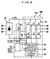
FIG. 9 shows an inverter device 50B, which is moduled in
a molded resin including inverter section and protective
circuits. A protective circuit 57 detects an overcurrent from
a current-detecting resistor 58 inserted between a capacitor 23
and an inverter section 51B, and also detects an overvoltage
across a resistor 59 connected parallel to a DC section of the
inverter device 50B. When the protective circuit 57 detects an
overcurrent or an overvoltage, the protective circuit 57 sends
a detected signal to the control circuit 53 including a CPU to
enable the control circuit 53 to perform a protective action as
by stopping the operation of the inverter device.
FIG. 10 shows an inverter device 50C which is encased,
together with the converter 22 and a rush current prevention
circuit 60, into an integral module by molded resin. The
converter 22 comprises bridge-connected rectifiers (diodes) for
rectifying a commercial three-phase AC power supply into a DC
electric power by way of full-wave rectification. The rush
current prevention circuit 60 serves to protect various circuit
components against an excessive surge current which rushes in
when a load device such as a pump starts to operate. The rush
current prevention circuit 60 comprises a rush prevention
resistor and a bypass circuit such as a thyristor which are
inserted parallel to each other. All the circuit components,
except the capacitor 23, of the inverter device 50C are encased
into a single module by molded resin.
FIG. 15 shows an appearance of this embodiment. A molded
block R of resin has ports 61R, 61S, 61T for passing output lines
connected to a motor and ports 62R, 62S, 62T for passing input
lines connected to a commercial AC power supply. Similarly, the
molded block R of resin has ports 63+, 63- for passing connector
lines connected to the capacitor 23. An interface board 65 is
disposed outside of the molded block R of resin and has interface
terminals 66 for connection to external signal lines.
Connection lines of the interface terminals 66 are connected to
a CPU of a control circuit which is encased in the molded block
R of resin.
Since circuit components including the CPU are encased in
the molded block R of resin, they are shielded from moisture
condensation and can operate normally. Even if there is a
temperature difference as when the inverter device is directly
installed on the casing of the pump, the inverter device can
easily be installed without the need for any special
countermeasures against moisture condensation. Therefore, the
inverter device can be reduced in cost and size.
FIG. 11 shows an inverter device 50D with a converter section
22 separated from an inverter section, installed on a separate
circuit board, and assembled as an integral module.
Specifically, the diode module 22 and the rush current prevention
circuit 60 are encased in a molded block R of resin, which has
ports 62R, 62S, 62T for connection to a commercial AC power supply
and ports 64+, 64- for connection to the inverter section.
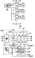
FIG. 12 shows a circuit arrangement in which a set of a
converter module 22A which is encased by molded resin and a
capacitor 23, is combined with a plurality of inverter section
modules, which are used to energize a plurality of motors M. Each
of the inverter section modules comprises the module 51A or 51B
shown in FIG. 8 or 9. The converter module comprises the
converter module 22A shown in FIG. 4. FIG. 16 shows a wired
arrangement of the converter module 22A, the capacitor 23, and
the inverter section modules. By using the converter module 22A
and as many inverter section modules 51A, 51B as the number of
motors, it is possible to eliminate any excessive circuit
components and reduce the cost and size of the inverter device.
FIG. 13 shows an inverter device 50E with a control power
supply circuit included in a converter module 22B. The control
power supply circuit 54 serves to supply a DC electric power of
+ 5 V or the like from a DC voltage stored in the capacitor 23
to the control circuit. Each of the inverter module 51B is not
necessarily required to be associated with the control power
supply circuit 54. Thus, the control power supply circuit 54
is included in the converter module 22B, but not in the inverter
section modules 51B. The inverter modules 51B can be supplied
with a control electric power from the control power supply
circuit 54 included in the converter module 22B. Accordingly,
the inverter device can further be reduced in cost.
FIG. 14 shows an example in which a converter module 22B
having a single control power supply circuit and a capacitor 23
are combined with a plurality of inverter section modules 51B.
Control circuits of the inverter section modules 51B operate by
being supplied with an electric power from the control power
supply circuit 54 included in the converter module 22B.
Since a CPU for controlling each inverter is combined with
an electrically rewritable memory such as a flash memory, for
example, then the control program of a module where the control
circuit is encased by molded resin can be rewritten via the
interface circuit. Consequently, the inverter device can easily
be used in many types of pump systems that are manufactured in
small lots.
Specifically, even after the inverter device has been
installed at a site, details of the program thereof can be
modified via the interface circuit, so that the pump or the like
can be operated with such characteristics as depending on
conditions of the installation site. Even if details of the
program need to be modified after the test, since they can easily
be rewritten via the interface circuit. Thus, such program
modifications can easily be made immediately at the installation
site. Even if it is necessary to modify operation
characteristics of the inverters due to an addition of
facilities, such a requirement can easily be met. Consequently,
the inverter device is rendered highly flexible.
According to the third embodiment of the present invention,
as described above, the inverter device is divided into a
converter section and an inverter section which is encased into
an integral module by molded resin. The inverter device can thus
be constructed as a module, and hence can be assembled and wired
with a reduced amount of labor and can be manufactured at a reduced
cost. Furthermore, the inverter device can be reduced in overall
size, and the cost thereof can be reduced as the number of packages
which have heretofore been required is reduced. Moreover,
inasmuch as any countermeasures for protecting the control
circuit against moisture condensation are not needed, the
inverter device according to the present invention can be
installed at sites where there is a temperature difference, e.g.,
directly in a pump casing. The inverter device can thus be used
highly conveniently.
A system for operating a plurality of pumps or fans with
a plurality of motors employs a converter and a plurality of
inverters. Therefore, the number of parts of the system is
greatly reduced, and hence the system is reduced in overall cost
and size. In addition, since the converter has a control power
supply circuit, when a plurality of motors are energized by a
plurality of inverter modules, the control circuits of the
respective inverters may be supplied with an electric power from
a single common control power supply circuit. Therefore, the
cost of manufacture of the system is further reduced.
By using an electrically rewritable memory such as a flash
memory or the like as a memory for storing a program for a control
circuit, the program can be rewritten even after the control
circuit has been encased by molded resin. Consequently, a
program can be added or modified even after the inverter device
has been manufactured or installed at the installation site.
A plurality of programs may be stored in advance, and one
of the programs may be selected via an interface circuit depending
on the use. Therefore, the present invention is easily
applicable to many types of systems that are manufactured in small
lots. The hardware arrangement can be reduced in cost as it can
be mass-produced.
Industrial Applicability
A rotary machine and control device combination according
to the present invention comprises a rotary machine such as a
pump, a fan, or the like and a control device integral therewith.
The rotary machine and control device combination is applicable
to a wide range of rotary machines such as pumps, fans, or the
like that can be controlled in speed by an inverter device. Such
pumps and fans can be used in variable-speed water supply
apparatus, air-conditioning systems, etc.