EP0936756B1 - Une architecture pour des stations de base avec des secteurs multiples - Google Patents
Une architecture pour des stations de base avec des secteurs multiples Download PDFInfo
- Publication number
- EP0936756B1 EP0936756B1 EP99300748A EP99300748A EP0936756B1 EP 0936756 B1 EP0936756 B1 EP 0936756B1 EP 99300748 A EP99300748 A EP 99300748A EP 99300748 A EP99300748 A EP 99300748A EP 0936756 B1 EP0936756 B1 EP 0936756B1
- Authority
- EP
- European Patent Office
- Prior art keywords
- signal
- radio
- sector
- antenna
- incoming signal
- Prior art date
- Legal status (The legal status is an assumption and is not a legal conclusion. Google has not performed a legal analysis and makes no representation as to the accuracy of the status listed.)
- Expired - Lifetime
Links
- 238000010586 diagram Methods 0.000 description 15
- 238000000034 method Methods 0.000 description 11
- 239000011159 matrix material Substances 0.000 description 10
- 230000005540 biological transmission Effects 0.000 description 6
- 238000005562 fading Methods 0.000 description 6
- 238000011176 pooling Methods 0.000 description 5
- 238000012876 topography Methods 0.000 description 2
- 230000003321 amplification Effects 0.000 description 1
- 230000005465 channeling Effects 0.000 description 1
- 238000004891 communication Methods 0.000 description 1
- 230000001419 dependent effect Effects 0.000 description 1
- 230000000694 effects Effects 0.000 description 1
- 238000005516 engineering process Methods 0.000 description 1
- 230000001788 irregular Effects 0.000 description 1
- 238000003199 nucleic acid amplification method Methods 0.000 description 1
- 230000005855 radiation Effects 0.000 description 1
Images


Classifications
-
- H—ELECTRICITY
- H04—ELECTRIC COMMUNICATION TECHNIQUE
- H04B—TRANSMISSION
- H04B7/00—Radio transmission systems, i.e. using radiation field
- H04B7/14—Relay systems
- H04B7/15—Active relay systems
- H04B7/155—Ground-based stations
-
- H—ELECTRICITY
- H04—ELECTRIC COMMUNICATION TECHNIQUE
- H04B—TRANSMISSION
- H04B7/00—Radio transmission systems, i.e. using radiation field
- H04B7/02—Diversity systems; Multi-antenna system, i.e. transmission or reception using multiple antennas
- H04B7/04—Diversity systems; Multi-antenna system, i.e. transmission or reception using multiple antennas using two or more spaced independent antennas
- H04B7/08—Diversity systems; Multi-antenna system, i.e. transmission or reception using multiple antennas using two or more spaced independent antennas at the receiving station
- H04B7/0837—Diversity systems; Multi-antenna system, i.e. transmission or reception using multiple antennas using two or more spaced independent antennas at the receiving station using pre-detection combining
- H04B7/0842—Weighted combining
Definitions
- the present invention relates to telecommunications in general, and, more particularly, to an architecture for a sectorized base station that is part of a wireless telecommunications system.
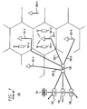
- FIG. 1 depicts a schematic diagram of a portion of a typical wireless telecommunications system, which provides wireless telecommunications service to a number of wireless terminals (e.g., wireless terminals 101-1 through 101-3) that are situated within a geographic region.
- the heart of a typical wireless telecommunications system is Wireless Switching Center ("WSC") 120, which might be known also as a Mobile Switching Center (“MSC”) or Mobile Telephone Switching Office (“MTSO”).
- WSC Wireless Switching Center
- MSC Mobile Switching Center
- MTSO Mobile Telephone Switching Office
- Wireless Switching Center 120 is connected to a plurality of base stations (e.g., base stations 103-1 through 103-5) that are dispersed throughout the geographic area serviced by the system and to the local and long-distance telephone offices (e.g., local-office 130, local-office 138 and toll-office 140).
- Wireless Switching Center 120 is responsible for, among other things, establishing and maintaining calls between wireless terminals and between a wireless terminal and a wireline terminal (e.g., wireline terminal 150), which wireline terminal is connected to Wireless Switching Center 120 via the local and/or long-distance networks.
- each cell is schematically represented by one hexagon in a honeycomb pattern; in practice, however, each cell has an irregular shape that depends on the topography of the terrain surrounding the cell.
- each cell contains a base station, which comprises the radios and antennas that the base station uses to communicate with the wireless terminals in that cell and also comprises the transmission equipment that the base station uses to communicate with Wireless Switching Center 120.
- wireless terminal 101-1 desires to communicate with wireless terminal 101-2
- wireless terminal 101-1 transmits the desired information to base station 103-1, which relays the information to Wireless Switching Center 120.
- Wireless Switching Center 120 Upon receipt of the information, and with the knowledge that it is intended for wireless terminal 101-2, Wireless Switching Center 120 then returns the information back to base station 103-1, which relays the information, via radio, to wireless terminal 101-2.
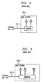
- FIG. 2 depicts a block diagram of a first base station architecture in the prior art, which comprises one or more radios that are capable of transmitting outgoing signals via a transmit antenna (" T x ”) and receiving incoming signals via a receive antenna (" Rx ").
- T x transmit antenna
- Rx receive antenna
- Each radio in this architecture receives one incoming carrier signal via the receive antenna and demodulates that carrier signal into one or more baseband signals in accordance with the particular access scheme employed (e.g., frequency-division multiple access, time-division multiple access, code-division multiple-access, etc.).
- the incoming baseband signals are then transmitted to wireless switching center 120.
- outgoing baseband signals from wireless switching center 120 are modulated by the radio in accordance with the particular multiplexing scheme employed (e.g., frequency-division multiplexing, time-division multiplexing, code-division multiplexing, etc.) for transmission via the transmission antenna.
- wireless telecommunications system 100 is a terrestrial system, in contrast to a satellite-based system, the quality and availability of service is subject to the idiosyncrasies of the terrain surrounding the system. For example, when the topography of the terrain is hilly or mountainous, or when objects such as buildings or trees are present, a signal transmitted by a wireless terminal can be absorbed or reflected such that the signal quality is not uniform at the base station. The result is that a base station's receive antenna can receive a direct path signal and one or more reflected signals from the wireless terminal at disparate phases such that the signals destructively interfere. This phenomenon is widely known as multipath fading or fast fading or Rayleigh fading.
- FIG. 3 depicts a block diagram of a second base station architecture in the prior art, which supports a technique known as N -way receive diversity to mitigate the effects of multipath fading.
- the base station architecture depicted in FIG. 3 comprises one or more radios that are capable of transmitting outgoing signals via a single transmit antenna, as in the architecture of FIG. 2, but also comprises N spatially-separate receive antennas ("Rx 1 ") through "Rx N " ) .
- Rx 1 N spatially-separate receive antennas
- Rx N N spatially-separate receive antennas
- a diversity combiner associated with the radios can combine N incoming signals, each from one of N receive antennas, using various techniques (e.g., selection diversity, equal gain combining diversity, maximum ratio combining diversity, etc.) to improve the reception of an incoming signal.
- various techniques e.g., selection diversity, equal gain combining diversity, maximum ratio combining diversity, etc.
- FIG. 4 depicts a block diagram of a third base station architecture in the prior art, which supports a technique for increasing the traffic capacity of the telecommunications system. This technique is known as "base station sectorization.”
- base station sectorization the cell serviced by a base station is subdivided into M tessellated pie-slices, each of which comprises a 360°/ M sector whose focus is at the base station.
- the base station architecture in FIG. 4 comprises M sets of radios and associated transmit and receive antennas, as shown, each of which operates independently of the others, except that the transmit and receive antennas associated with each sector are generally implemented so as to principally transmit into and receive from that sector.
- the architecture in FIG. 4 is, however, disadvantageous because it requires more radios than necessary to support a given traffic capacity, which unnecessarily increases the cost of the base station.
- the same average traffic capacity can be accommodated with fewer radios if they are pooled, as depicted in FIG. 5.
- FIG. 5 depicts a block diagram of a fourth base station architecture in the prior art, which supports receive diversity, sectorization, and radio pooling.
- the architecture comprises: a plurality of radios 501-1 through 501-Z, sniffer radio 502, switch matrix 503, and M sets of transmit and receive antennas 504-1 through 504- M , interconnected as shown.
- sniffer radio 502 scans all of the potential sectors and channels in search of incoming signals. When sniffer radio 502 detects an incoming signal from a given sector, it directs switch matrix 503 to route the incoming signals from that sector to an appropriate radio and to route the outgoing signals from that radio to the same sector.
- this architecture requires fewer radios to support the same average traffic capacity as the architecture in FIG. 4.
- This architecture is disadvantageous, however, in that it requires a sniffer radio and a complex M ⁇ (N + 1) + 2 by M ⁇ ( N + 1) switch matrix to be added to the base station.
- EP-A-0 797 369 is directed to a sector selection scheme for a CDMA communication system with a sector configuration.
- a base station includes antennas connected to duplexers so that each antenna may be used for reception and transmission. Received signals may be sent via RF reception amplifiers to a transceiver.
- the receiver side of the transceiver includes a switching circuit and a reception selection circuit. To select a sector for receiving data on one of the antennas, one or more sectors is first selected by the reception sector selection unit.
- the signals are provided to the switching circuit, which supplies the received signals from the RF reception amplifiers of the selected sector to correlators, based on the selection result obtained by the reception sector selection unit.
- WO-A-96 22 002 is directed to a method for channeling transmit power in a desired direction into a base station which communicates with a plurality of subscriber terminals within the base station coverage area.
- a receiver unit of the base station includes means which combines signals from four receiver antennas so that a control unit can process four signals. Accordingly, each of three sectors can each be realized with four antennas that are orientated adjacent to each other, so that antenna beams form four adjacent sectors.
- Apparatus according to the invention is as set out in claim 1. Preferred forms are set out in the dependent claims.
- the present invention is a base station architecture that supports receive diversity, sectorization, and radio pooling without some of the costs and disadvantages associated with base station architectures in the prior art.
- some embodiments of the present invention avoid the need for a sniffer radio or a switching matrix between the radios and the receive antennas. This is advantageous because it reduces the cost and size of a base station.
- the sniffer radio in the prior art base station architecture is actually performing a disservice to the functioning of the base station. For example, in any given interval a wireless terminal engaged in a call with a radio in the base station can move from one sector to another. If the sniffer radio in the base station becomes aware of that movement too long after it has occurred, then the call might be dropped by the base station. But because the sniffer radio searches for only one incoming signal at a time, it can be a considerable amount of time before the sniffer radio detects the movement of a wireless terminal. Therefore, the sniffer radio is a bottleneck in the operation of the base station.
- the existence of the sniffer radio and the switch matrix only allows each radio to utilize the incoming signals from one sector of receive antennas at a time, which deprives the radio of useful incoming signals that might be available at other receive antennas.
- the technique of sectorization increases the traffic capacity of the system, it is not necessary to sectorization that each radio be restricted to receiving incoming signals from only one sector's antennas. It is only necessary that the frequencies intentionally transmitted in a sector be distinct from the frequencies transmitted in adjacent sectors.
- a more advantageous architecture allows each radio to receive incoming signals from all of the receive antennas at the base station and to perform diversity combining and/or beamforming on all of the incoming signals. This is advantageous because it eliminates the need for the sniffer radio and the switch matrix between the radios and the receive antennas. Furthermore, because each radio receives incoming signals from all of the receive antennas all of the time, the radio can continually monitor the movement of the wireless terminal, which effectively precludes the possibility that a call would be dropped because the radio failed to detect the movement of a wireless terminal across a sector boundary.
- An illustrative embodiment of the present invention comprises: a first receive antenna for receiving a first incoming signal; a second receive antenna for receiving a second incoming signal; a first transmit antenna for transmitting into a first sector; a second transmit antenna for transmitting into a second sector; a first switch for receiving a first outgoing signal and a first control signal, and for routing the first outgoing signal to at least one of the first transmit antenna and the second transmit antenna based on the first control signal; and a first radio for receiving the first incoming signal from the first receive antenna and the second incoming signal from the second receive antenna, and for providing the first outgoing signal and the first control signal to the first switch.
- FIG. 6 depicts a block diagram of a base station architecture in accordance with the illustrative embodiment of the present invention, which supports receive diversity, sectorization and radio pooling.
- the illustrative embodiment advantageously comprises: a plurality of radios 601-1 through 601- Z , M -way switches 607-1 through 607-Z, combiner/amplifier 603, M sets of sectorized transmit antennas, and M sets of receive antennas 606-1 through 606- M , interconnected as shown.
- each transmit antenna is associated with a sector
- each set of receive antennas can, but is not necessarily, also associated with a sector. Instead, in accordance with the illustrative embodiment of the present invention, each receive antenna can receive omni-directionally or can have a field of view that is wider or narrower than the sectors associated with the transmit antennas.
- Each set of N receive antennas captures N versions of an incoming signal from a wireless terminal (not shown).
- the illustrative embodiment advantageously comprises Z radios, each of which is capable of receiving and demodulating one incoming signal of interest from a wireless terminal and of creating therefrom one or more baseband signals in accordance with the particular access scheme employed (e.g., frequency-division multiple access, time-division multiple access, code-division multiple-access, etc.). Each radio is also capable of transmitting those baseband signals to a wireless switching center, in well-known fashion.
- Z radios each of which is capable of receiving and demodulating one incoming signal of interest from a wireless terminal and of creating therefrom one or more baseband signals in accordance with the particular access scheme employed (e.g., frequency-division multiple access, time-division multiple access, code-division multiple-access, etc.).
- Each radio is also capable of transmitting those baseband signals to a wireless switching center, in well-known fashion.
- Each radio advantageously comprises a diversity processor and a beamforming processor that are capable of increasing the fidelity of the incoming signal of interest by receiving N x M variations of the incoming signal (i.e., N variations from M sectors) and performing N x M - way diversity combining and/or beamforming, in well-known fashion, on those variations.
- This architecture is advantageous for four reasons. First, no sniffer radio is needed. Second, no switch matrix is needed between the receive antennas and the respective radios. Third, diversity combining and/or beamforming is now possible across sector boundaries, and fourth, the additional cost incurred by radios that are capable of N x M - way diversity combining and beamforming is more than offset by the cost savings associated with the omission of the sniffer radio and switch matrix.
- Each radio, radio i , for 1 ⁇ i ⁇ Z is advantageously capable of receiving one or more baseband signals from a wireless switching center and of creating an outgoing signal based on those baseband signals in accordance with a given multiplexing scheme (e.g. , frequency-division multiplexing, time-division multiplexing, code-division multiplexing, etc.), in well-known fashion.
- That output signal is advantageously output from radio i to switch 607-i via lead 602- i .
- Each radio is advantageously capable of analyzing the N x M variations of the incoming signal, in well-known fashion, to generate an estimate of the sector from which the incoming signal originates. This information is useful because each radio uses the estimate to generate a control signal, control signal # i on lead 603- i , to route the outgoing signal from the radio to the transmit antenna(s) associated with the sector(s) from which the radio estimates the incoming signal originates.
- Each radio, radio i advantageously directs switch 607- i which transmit antenna to use by transmitting a control signal on lead 603- i to switch 607- i .
- M -way switch matrix 607- i for 1 ⁇ i ⁇ Z , advantageously receives from radio 601- i : (1) outgoing signal # i on lead 602- i , and (2) control signal # i on lead 603- i , and routes outgoing signal # i to one or more transmit antennas under the direction of control signal # i . It will be clear to those skilled in the art how to make and use M -way switch matrix 701- i .
- the output(s) of switch 607- i are fed into combiner/amplifier 603, which combines two or more signals for the same transmit antenna and amplifies the signals prior to transmission.
- FIG. 7 depicts a block diagram of amplifier/combiner 603, which advantageously comprises: M combiners 702-1 through 702- M and M power amplifiers 703-1 through 703- M .
- Combiner 702- j for 1 ⁇ j ⁇ Z , is uniquely associated with sector j and receives all of the outgoing signals intended for sector j and vector sums them in well-known fashion.
- the output of combiner 702-j is fed into power amplifier 703- j for amplification prior to radiation via sector j transmit antenna. It will be clear to those skilled in the art how to make and use antenna router 603.
- FIG. 8 depicts a flowchart of the operation of the illustrative embodiment of the present invention, which is summarized in five steps. It will be clear to those skilled in the art that the illustrative embodiment operates computationally like a multiprocessor computer and that aspects of all five steps are being performed simultaneously by one component of the illustrative embodiment or another at virtually all times. The pedagogical purpose of the flowchart is to highlight some of the causality associated with the operation of the illustrative embodiment.
- a radio receives N x M variations of an incoming signal from all N x M receive antennas, and at step 802 the radio uses N x M - way diversity combination and/or beamforming techniques to create an estimate of the incoming signal that is better than any one variation of the incoming signal.
- the radio analyzes the N x M variations of the incoming signal to create an estimate of the most likely sector or sectors from which the incoming signal originates, and at step 804 the radio generates an outgoing signal to the wireless terminal.
- the radio then directs antenna router 603 to route the outgoing signal to the transmit antenna(s) associated with the sector or sectors from which the incoming signal is believed to originate. From step 805, control returns to step 801.
Landscapes
- Engineering & Computer Science (AREA)
- Computer Networks & Wireless Communication (AREA)
- Signal Processing (AREA)
- Mobile Radio Communication Systems (AREA)
Claims (5)
- Appareil comprenant :CARACTERISE PARune première antenne de réception (Rx1 de 606-1) pour recevoir un premier signal d'arrivée (604-1) d'un premier secteur (secteur 1) ;une deuxième antenne de réception (RxN de 606-1) pour recevoir un deuxième signal d'arrivée (60N-1) dudit premier secteur ;une première antenne d'émission (Tx de 606-1) pour émettre dans ledit premier secteur ;une deuxième antenne d'émission (Tx de 606-M) pour émettre dans un deuxième secteur (secteur M) ;un premier commutateur (607-1) pour recevoir un premier signal de départ (602-1) et un premier signal de contrôle (603-1), et pour acheminer ledit premier signal de départ à au moins une de ladite première antenne d'émission et ladite deuxième antenne d'émission en se basant sur ledit premier signal de contrôle ; l'appareil étant
une troisième antenne de réception (Rx1 de 606-M) pour recevoir un troisième signal d'arrivée (604-M) dudit deuxième secteur ;
une quatrième antenne de réception (RxN de 606-M) pour recevoir un quatrième signal d'arrivée (60N-M) dudit deuxième secteur ;
une première radio pour recevoir simultanément ledit premier signal d'arrivée de ladite première antenne de réception, ledit deuxième signal d'arrivée de ladite deuxième antenne de réception, ledit troisième signal d'arrivée de ladite troisième antenne, et ledit quatrième signal d'arrivée de ladite quatrième antenne, pour fournir au moins la diversité de quatre moyens de combiner ledit premier signal, ledit deuxième signal, ledit troisième signal, et ledit quatrième signal, et pour fournir ledit premier signal de départ et ledit premier signal de contrôle audit premier commutateur. - Appareil selon la revendication 1, en outre CARACTERISE PAR :un deuxième commutateur (607-Z) pour recevoir un deuxième signal de départ (602-Z) et un deuxième signal de contrôle (603-Z), et pour acheminer ledit deuxième signal de départ à au moins une de ladite première antenne d'émission et ladite deuxième antenne d'émission en se basant sur ledit deuxième signal de contrôle ; etune deuxième radio pour recevoir simultanément ledit premier signal d'arrivée de ladite première antenne de réception, ledit deuxième signal d'arrivée de ladite deuxième antenne de réception, ledit troisième signal d'arrivée de ladite troisième antenne, et ledit quatrième signal d'arrivée de ladite quatrième antenne, et pour fournir ledit deuxième signal de départ et ledit deuxième signal de contrôle audit deuxième commutateur.
- Appareil selon la revendication 1, CARACTERISE EN CE QUE ladite première radio comprend ledit premier commutateur.
- Appareil selon la revendication 1, CARACTERISE EN CE QUE ladite première radio comprend un processeur de diversité pour combiner ledit premier signal d'arrivée de ladite première antenne de réception, ledit deuxième signal d'arrivée de ladite deuxième antenne de réception, ledit troisième signal d'arrivée de ladite troisième antenne de réception, et ledit quatrième signal d'arrivée de ladite quatrième antenne de réception.
- Appareil selon la revendication 1, CARACTERISE EN CE QUE ladite première radio comprend un processeur de formation de faisceau pour combiner ledit premier signal d'arrivée de ladite première antenne de réception, ledit deuxième signal d'arrivée de ladite deuxième antenne de réception, ledit troisième signal d'arrivée de ladite troisième antenne de réception, et ledit quatrième signal d'arrivée de ladite quatrième antenne de réception.
Applications Claiming Priority (2)
| Application Number | Priority Date | Filing Date | Title |
|---|---|---|---|
| US23439 | 1993-02-26 | ||
| US09/023,439 US6148218A (en) | 1998-02-13 | 1998-02-13 | Architecture for multi-sector base stations |
Publications (3)
| Publication Number | Publication Date |
|---|---|
| EP0936756A2 EP0936756A2 (fr) | 1999-08-18 |
| EP0936756A3 EP0936756A3 (fr) | 2003-01-29 |
| EP0936756B1 true EP0936756B1 (fr) | 2005-04-13 |
Family
ID=21815114
Family Applications (1)
| Application Number | Title | Priority Date | Filing Date |
|---|---|---|---|
| EP99300748A Expired - Lifetime EP0936756B1 (fr) | 1998-02-13 | 1999-02-02 | Une architecture pour des stations de base avec des secteurs multiples |
Country Status (9)
| Country | Link |
|---|---|
| US (1) | US6148218A (fr) |
| EP (1) | EP0936756B1 (fr) |
| JP (1) | JP3730042B2 (fr) |
| KR (1) | KR100347846B1 (fr) |
| CN (1) | CN1230864A (fr) |
| AU (1) | AU751663B2 (fr) |
| BR (1) | BR9900734B1 (fr) |
| CA (1) | CA2260663C (fr) |
| DE (1) | DE69924656T2 (fr) |
Families Citing this family (15)
| Publication number | Priority date | Publication date | Assignee | Title |
|---|---|---|---|---|
| US6405018B1 (en) * | 1999-01-11 | 2002-06-11 | Metawave Communications Corporation | Indoor distributed microcell |
| KR100312451B1 (ko) * | 1999-07-07 | 2001-11-03 | 박종섭 | 다중섹터 기지국에서 디지털 유니트내 스위칭 장치 |
| US6594475B1 (en) * | 1999-09-09 | 2003-07-15 | International Business Machines Corporation | Mobile battery discharge minimization in indoor wireless networks by antenna switching |
| FI108196B (fi) * | 1999-09-30 | 2001-11-30 | Nokia Networks Oy | Järjestely ja menetelmä radiojärjestelmän lähetinvastaanotintoiminnan toteuttamiseksi |
| JP2001168778A (ja) * | 1999-12-06 | 2001-06-22 | Matsushita Electric Ind Co Ltd | 無線通信基地局 |
| US6678508B1 (en) * | 2000-02-07 | 2004-01-13 | Ericsson Inc. | Power conservation method for mobile communications device with two receivers |
| KR20010107015A (ko) * | 2000-05-24 | 2001-12-07 | 윤종용 | 피코 기지국의 무선신호 송수신 장치 |
| US6539209B1 (en) * | 2000-05-30 | 2003-03-25 | Lucent Technologies Inc. | Code-division, multiple-access base station having transmit diversity |
| US20040185782A1 (en) * | 2003-03-17 | 2004-09-23 | Halford Steven Dennis | Technique for selecting a signal path in an antenna system |
| US7079816B2 (en) * | 2003-04-25 | 2006-07-18 | Broadcom Corporation | On chip diversity antenna switch |
| CN100382459C (zh) * | 2004-04-20 | 2008-04-16 | 华为技术有限公司 | 一种射频信号接收单元和方法 |
| US20050255888A1 (en) * | 2004-05-14 | 2005-11-17 | Cooper Stephen E | Base station for a mobile telecommunications network employing diversity and method of operation |
| JP5450638B2 (ja) * | 2008-10-30 | 2014-03-26 | アルカテル−ルーセント | マルチセクタ協調通信における協調タイプの切り替え技術 |
| CN108123747B (zh) * | 2014-09-16 | 2020-08-04 | 安科讯(福建)科技有限公司 | 一种基于扇区切换的wlan基站信号覆盖方法 |
| JP7124506B2 (ja) * | 2018-07-17 | 2022-08-24 | 日本電信電話株式会社 | 集音拡声装置、その方法、およびプログラム |
Family Cites Families (4)
| Publication number | Priority date | Publication date | Assignee | Title |
|---|---|---|---|---|
| US5504936A (en) * | 1991-04-02 | 1996-04-02 | Airtouch Communications Of California | Microcells for digital cellular telephone systems |
| GB2271246B (en) * | 1992-10-03 | 1997-02-12 | Motorola Ltd | Sectorized cellular radio base station antenna |
| FI950093L (fi) * | 1995-01-09 | 1996-07-10 | Nokia Telecommunications Oy | Tukiasema ja menetelmä lähetystehon ohjaamiseksi haluttuun suuntaan |
| US6011787A (en) * | 1996-03-21 | 2000-01-04 | Ntt Mobile Communications Network Inc. | CDMA mobile communication scheme with effective use of sector configuration |
-
1998
- 1998-02-13 US US09/023,439 patent/US6148218A/en not_active Expired - Lifetime
-
1999
- 1999-02-02 CA CA002260663A patent/CA2260663C/fr not_active Expired - Lifetime
- 1999-02-02 DE DE69924656T patent/DE69924656T2/de not_active Expired - Lifetime
- 1999-02-02 EP EP99300748A patent/EP0936756B1/fr not_active Expired - Lifetime
- 1999-02-10 KR KR1019990004552A patent/KR100347846B1/ko not_active Expired - Lifetime
- 1999-02-10 AU AU16379/99A patent/AU751663B2/en not_active Expired
- 1999-02-12 CN CN99102305A patent/CN1230864A/zh active Pending
- 1999-02-12 BR BRPI9900734-7A patent/BR9900734B1/pt not_active IP Right Cessation
- 1999-02-15 JP JP03574199A patent/JP3730042B2/ja not_active Expired - Lifetime
Also Published As
| Publication number | Publication date |
|---|---|
| DE69924656D1 (de) | 2005-05-19 |
| JP3730042B2 (ja) | 2005-12-21 |
| AU751663B2 (en) | 2002-08-22 |
| KR100347846B1 (ko) | 2002-08-07 |
| CN1230864A (zh) | 1999-10-06 |
| AU1637999A (en) | 1999-08-26 |
| EP0936756A2 (fr) | 1999-08-18 |
| CA2260663C (fr) | 2003-03-25 |
| KR19990072538A (ko) | 1999-09-27 |
| EP0936756A3 (fr) | 2003-01-29 |
| JP2000040993A (ja) | 2000-02-08 |
| HK1022795A1 (en) | 2000-08-18 |
| CA2260663A1 (fr) | 1999-08-13 |
| US6148218A (en) | 2000-11-14 |
| BR9900734A (pt) | 2000-01-18 |
| BR9900734B1 (pt) | 2012-02-07 |
| DE69924656T2 (de) | 2006-02-09 |
Similar Documents
| Publication | Publication Date | Title |
|---|---|---|
| EP0953235B1 (fr) | Systeme de communication sans fil amrc a antenne intelligente | |
| US7099697B2 (en) | Base station, mobile communication system, and communication method | |
| JP4416820B2 (ja) | 分散送信源を基盤とする多重入出力通信方法 | |
| US6055230A (en) | Embedded digital beam switching | |
| US7411899B2 (en) | Apparatus and method for allocating walsh codes to access terminals in an adaptive antenna array CDMA wireless network | |
| EP0936756B1 (fr) | Une architecture pour des stations de base avec des secteurs multiples | |
| EP1063791A2 (fr) | Méthode de communication à accès multiple par division de code utilisant un assignement de code dynamique, et station de base pour cette méthode | |
| JP2003514431A (ja) | アンテナのアレイを使用したcdmaシステム内でのダウンリンク信号処理 | |
| US6535733B1 (en) | Measurement radio system for producing operating information for traffic radios | |
| JP2000509950A (ja) | 通信を改善する方法及びシステム | |
| EP0763307A2 (fr) | Systeme de combinaison en diversite pour antennes | |
| US6212387B1 (en) | Method and apparatus for collector arrays of directional antennas co-located with zone managers in wireless communications systems | |
| EP1401120A2 (fr) | Station de base, système de communication mobile et procédé de communication | |
| US6275482B1 (en) | Combined angular, spatial, and temporal diversity for mobile radio system | |
| CA2260281C (fr) | Architecture de systeme de telecommunications sans fil prenant en charge la diversite de reception | |
| CN108123743B (zh) | 基于多扇区的wlan基站信号收发方法 | |
| EP2154793A2 (fr) | Système de commutation dynamique et procédé entre une transmission d'antenne simple et multiple | |
| JP2001203623A (ja) | 基地局アンテナシステム | |
| US8179834B2 (en) | Method and apparatus for adapting downlink wireless transmission between beamforming and transmit diversity on a per mobile station basis | |
| HK1022795B (en) | An architecture for multi-sector base stations | |
| KR20010058972A (ko) | 스마트 안테나를 이용한 무선가입자망 시스템 | |
| KR20000000645A (ko) | 코드분할 다중접속 셀룰러 이동 통신 시스템의 다이버시티송신 방법 및 장치 | |
| EP1192742A1 (fr) | Traducteur pour un systeme radio a acces multiple par repartition dans le temps a circuits de diversite separes |
Legal Events
| Date | Code | Title | Description |
|---|---|---|---|
| PUAI | Public reference made under article 153(3) epc to a published international application that has entered the european phase |
Free format text: ORIGINAL CODE: 0009012 |
|
| AK | Designated contracting states |
Kind code of ref document: A2 Designated state(s): AT BE CH CY DE DK ES FI FR GB GR IE IT LI LU MC NL PT SE |
|
| AX | Request for extension of the european patent |
Free format text: AL;LT;LV;MK;RO;SI |
|
| PUAL | Search report despatched |
Free format text: ORIGINAL CODE: 0009013 |
|
| AK | Designated contracting states |
Designated state(s): AT BE CH CY DE DK ES FI FR GB GR IE IT LI LU MC NL PT SE |
|
| AX | Request for extension of the european patent |
Extension state: AL LT LV MK RO SI |
|
| RIC1 | Information provided on ipc code assigned before grant |
Ipc: 7H 04B 7/04 B Ipc: 7H 04B 7/06 B Ipc: 7H 04B 7/08 A |
|
| 17P | Request for examination filed |
Effective date: 20030721 |
|
| AKX | Designation fees paid |
Designated state(s): DE FI FR GB SE |
|
| 17Q | First examination report despatched |
Effective date: 20031006 |
|
| GRAP | Despatch of communication of intention to grant a patent |
Free format text: ORIGINAL CODE: EPIDOSNIGR1 |
|
| GRAS | Grant fee paid |
Free format text: ORIGINAL CODE: EPIDOSNIGR3 |
|
| GRAA | (expected) grant |
Free format text: ORIGINAL CODE: 0009210 |
|
| AK | Designated contracting states |
Kind code of ref document: B1 Designated state(s): DE FI FR GB SE |
|
| REG | Reference to a national code |
Ref country code: GB Ref legal event code: FG4D |
|
| REG | Reference to a national code |
Ref country code: IE Ref legal event code: FG4D |
|
| REF | Corresponds to: |
Ref document number: 69924656 Country of ref document: DE Date of ref document: 20050519 Kind code of ref document: P |
|
| REG | Reference to a national code |
Ref country code: SE Ref legal event code: TRGR |
|
| REG | Reference to a national code |
Ref country code: HK Ref legal event code: GR Ref document number: 1022795 Country of ref document: HK |
|
| PLBE | No opposition filed within time limit |
Free format text: ORIGINAL CODE: 0009261 |
|
| STAA | Information on the status of an ep patent application or granted ep patent |
Free format text: STATUS: NO OPPOSITION FILED WITHIN TIME LIMIT |
|
| ET | Fr: translation filed | ||
| 26N | No opposition filed |
Effective date: 20060116 |
|
| REG | Reference to a national code |
Ref country code: GB Ref legal event code: 732E Free format text: REGISTERED BETWEEN 20131031 AND 20131106 |
|
| REG | Reference to a national code |
Ref country code: FR Ref legal event code: CD Owner name: ALCATEL-LUCENT USA INC. Effective date: 20131122 |
|
| REG | Reference to a national code |
Ref country code: FR Ref legal event code: GC Effective date: 20140410 |
|
| REG | Reference to a national code |
Ref country code: FR Ref legal event code: RG Effective date: 20141015 |
|
| REG | Reference to a national code |
Ref country code: FR Ref legal event code: PLFP Year of fee payment: 17 |
|
| REG | Reference to a national code |
Ref country code: FR Ref legal event code: PLFP Year of fee payment: 18 |
|
| REG | Reference to a national code |
Ref country code: FR Ref legal event code: PLFP Year of fee payment: 19 |
|
| REG | Reference to a national code |
Ref country code: FR Ref legal event code: PLFP Year of fee payment: 20 |
|
| PGFP | Annual fee paid to national office [announced via postgrant information from national office to epo] |
Ref country code: FI Payment date: 20180219 Year of fee payment: 20 Ref country code: DE Payment date: 20180219 Year of fee payment: 20 Ref country code: GB Payment date: 20180216 Year of fee payment: 20 |
|
| PGFP | Annual fee paid to national office [announced via postgrant information from national office to epo] |
Ref country code: FR Payment date: 20180222 Year of fee payment: 20 Ref country code: SE Payment date: 20180227 Year of fee payment: 20 |
|
| REG | Reference to a national code |
Ref country code: DE Ref legal event code: R071 Ref document number: 69924656 Country of ref document: DE |
|
| REG | Reference to a national code |
Ref country code: GB Ref legal event code: PE20 Expiry date: 20190201 |
|
| REG | Reference to a national code |
Ref country code: SE Ref legal event code: EUG |
|
| PG25 | Lapsed in a contracting state [announced via postgrant information from national office to epo] |
Ref country code: GB Free format text: LAPSE BECAUSE OF EXPIRATION OF PROTECTION Effective date: 20190201 |