EP0937206B1 - Moteur de positionnement pneumatique ou hydraulique muni d'un dispositif de desenclenchement - Google Patents
Moteur de positionnement pneumatique ou hydraulique muni d'un dispositif de desenclenchement Download PDFInfo
- Publication number
- EP0937206B1 EP0937206B1 EP97951167A EP97951167A EP0937206B1 EP 0937206 B1 EP0937206 B1 EP 0937206B1 EP 97951167 A EP97951167 A EP 97951167A EP 97951167 A EP97951167 A EP 97951167A EP 0937206 B1 EP0937206 B1 EP 0937206B1
- Authority
- EP
- European Patent Office
- Prior art keywords
- piston
- loose
- pressure
- actuator
- working piston
- Prior art date
- Legal status (The legal status is an assumption and is not a legal conclusion. Google has not performed a legal analysis and makes no representation as to the accuracy of the status listed.)
- Expired - Lifetime
Links
- 238000007789 sealing Methods 0.000 claims description 35
- 238000005553 drilling Methods 0.000 description 2
- 230000001105 regulatory effect Effects 0.000 description 2
- 238000010276 construction Methods 0.000 description 1
- 238000006073 displacement reaction Methods 0.000 description 1
- 210000003746 feather Anatomy 0.000 description 1
- 238000004898 kneading Methods 0.000 description 1
- 238000005096 rolling process Methods 0.000 description 1
Images

Classifications
-
- F—MECHANICAL ENGINEERING; LIGHTING; HEATING; WEAPONS; BLASTING
- F15—FLUID-PRESSURE ACTUATORS; HYDRAULICS OR PNEUMATICS IN GENERAL
- F15B—SYSTEMS ACTING BY MEANS OF FLUIDS IN GENERAL; FLUID-PRESSURE ACTUATORS, e.g. SERVOMOTORS; DETAILS OF FLUID-PRESSURE SYSTEMS, NOT OTHERWISE PROVIDED FOR
- F15B15/00—Fluid-actuated devices for displacing a member from one position to another; Gearing associated therewith
- F15B15/20—Other details, e.g. assembly with regulating devices
-
- F—MECHANICAL ENGINEERING; LIGHTING; HEATING; WEAPONS; BLASTING
- F15—FLUID-PRESSURE ACTUATORS; HYDRAULICS OR PNEUMATICS IN GENERAL
- F15B—SYSTEMS ACTING BY MEANS OF FLUIDS IN GENERAL; FLUID-PRESSURE ACTUATORS, e.g. SERVOMOTORS; DETAILS OF FLUID-PRESSURE SYSTEMS, NOT OTHERWISE PROVIDED FOR
- F15B15/00—Fluid-actuated devices for displacing a member from one position to another; Gearing associated therewith
- F15B15/20—Other details, e.g. assembly with regulating devices
- F15B15/22—Other details, e.g. assembly with regulating devices for accelerating or decelerating the stroke
- F15B15/225—Other details, e.g. assembly with regulating devices for accelerating or decelerating the stroke with valve stems operated by contact with the piston end face or with the cylinder wall
-
- B—PERFORMING OPERATIONS; TRANSPORTING
- B62—LAND VEHICLES FOR TRAVELLING OTHERWISE THAN ON RAILS
- B62D—MOTOR VEHICLES; TRAILERS
- B62D5/00—Power-assisted or power-driven steering
- B62D5/06—Power-assisted or power-driven steering fluid, i.e. using a pressurised fluid for most or all the force required for steering a vehicle
- B62D5/061—Power-assisted or power-driven steering fluid, i.e. using a pressurised fluid for most or all the force required for steering a vehicle provided with effort, steering lock, or end-of-stroke limiters
-
- B—PERFORMING OPERATIONS; TRANSPORTING
- B62—LAND VEHICLES FOR TRAVELLING OTHERWISE THAN ON RAILS
- B62D—MOTOR VEHICLES; TRAILERS
- B62D5/00—Power-assisted or power-driven steering
- B62D5/06—Power-assisted or power-driven steering fluid, i.e. using a pressurised fluid for most or all the force required for steering a vehicle
- B62D5/10—Power-assisted or power-driven steering fluid, i.e. using a pressurised fluid for most or all the force required for steering a vehicle characterised by type of power unit
- B62D5/12—Piston and cylinder
Definitions
- the invention relates to a pneumatic or hydraulic Actuator, in which a shutdown device is provided in the end positions of a working piston.
- the invention relates to an auxiliary power steering device, especially for motor vehicles with a pressure oil pump, a steering valve and a servo motor.
- Such shutdown devices are said to start hard prevent the piston against the end stops, because it’s associated with noise.
- the pump pressure increases from the working piston to the end stops to an unacceptable level, so that the built-in pressure relief valve responds. If the steering valve deflected for a long time in this operating state the pump may remain due to thermal overload Get damaged.
- a shutdown device for power steering is z. B. known from DE 42 21 459 A1.
- the pressure oil can therefore Relax via the pressure connection on the inactive pressure side and drain off.
- This relief path in the end positions of the Servomotors take place via a longitudinal groove in the inner wall of the servo cylinder connected to the pressure connection is coming.
- This connection in the end positions is put through Driving over the longitudinal groove through the working piston.
- a such switch-off device can when turning back into the other steering direction but do not build up any pressure at first, because the working piston first covers a short distance must to close the longitudinal groove. During this There is no servo power available and the driver must apply the entire steering force by hand.
- a shutdown device for a working piston is known, with a movable ball-spring unit in the working piston is inserted.
- One ball seals each a bypass channel to the relieved pressure chamber on a sealing edge of the working piston.
- By stop on a projecting edge in the two end positions of the Servo cylinder is one ball from the associated one The sealing edge is pushed away so that both pressure chambers are connected to step.
- the object of the invention is the shutdown device to be coordinated so that at the beginning of the steering back the servo power is available from one end position stands. To avoid noise, a large flow cross-section should be used of the bypass channel.
- the Auxiliary steering device should meet the requirement as possible meet low construction costs.
- control edges have the Task, for a soft start of the loose piston to the To ensure sealing edges. If a soft start is not necessary, the control edges can be omitted.
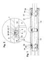
- the working piston 3 is positively attached to the piston rod 2 by rolling or kneading.
- the divided working piston 3 contains a groove 4 in which a loose piston 5 with sealing rings 5A, 5B is inserted so as to be axially displaceable.
- the working piston 3 seals off a bypass channel 8 with sealing edges 6 or 7 on one of the end faces of the loose piston 5.
- the bypass channel 8 is incorporated in the form of one or more longitudinal grooves or as an annular gap in the working piston 3 or in the loose piston 5.
- the loose piston 5 regulates the oil flow in the bypass channel 8 on the working piston 3 either with a control edge 10 or 11.
- the loose piston 5 and the working piston 3 divide the cylinder tube 1 into two pressure chambers 12 and 13.
- Socket 14 and 15 At the ends of the cylinder tube 1 there are one Socket 14 and 15 with a stepped collar 16 and 17 and an end stop 26, 27 installed.
- the socket 14, 15 has also the task of an annular groove 18, 20 and one Bore 21, 22 a connection from the oil connection 23, 24 in to produce the pressure chamber 12 or 13.
- the loose piston 5 is in the sealing position the sealing edge 7.
- the loose piston 5 covers the Control edge 11 while the control edge 10 is open.
- the operating pressure in the pressure chamber 12 can be due to the closed Do not relax the sealing edge 7 to the pressure chamber 13.
- the working piston 3 with the loose piston 5 moves up to Bushing 15.
- the collar 17 of the bushing 15 abuts the end stop against the loose piston 5 and moves it to a central position, in which the sealing edge 7 and the control edge 11 open become.
- This central position of the loose piston 5 is through the system of the working piston 3 at the end stop 27 of the socket 15 determined.
- the operating pressure in the pressure chamber 12 relaxes thereupon about the pressure chamber 13 and the Oil connection 24 to an oil tank, not shown.
- the return oil flowing past the sealing edge 6 almost without pressure holds the loose piston 5 in the open position Confederation 17th
- the steering valve is adjusted with the rotation of the Steering handwheel in the opposite direction.
- the operating pressure flows on it via the oil connection 24 into the pressure chamber 13 and the loose piston 5 is pressed against the sealing edge 6.
- the working piston 3 moves together with the Loose piston 5 to the left.
- the closing movement of the loose piston 5th control so that it is dampened on its sealing edges 6 or 7 creates.
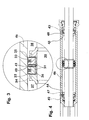
- FIGS. 3 and 4 of the invention Another embodiment is shown in FIGS. 3 and 4 of the invention.
- One fixed on a piston rod 30 and two-part working piston 31 carries the loose piston 32 and 33.
- the loose pistons 32, 33 seal with the external ones End faces against the sealing edges 34 and 35.
- a bypass channel 36 can the pressure rooms 37 and 38, depending on the position the loose piston 32, 33, interconnect.
- Between a chamber 40 is formed for the two loose pistons 32 and 33, which receives a spring 41, preferably a plate spring.
- the spring 41 presses the loose pistons 32 and 33 apart and holds them on the sealing edges 34 and 35 of the working piston 31 in Appendix.
- In the end positions are as stops again bushings 42 and 43 with offset collars 44 and 45 pressed into the cylinder tube 46.
- the working piston 31 moves together with the loose pistons 32, 33 e.g. B. by the operating pressure in the pressure chamber 37 to the right.
- the Pressure in chamber 40 thereby occurs with the return pressure of the pressure chamber 38 in connection and relaxes to one Oilcontainer.
- Moved by the operating pressure in the pressure chamber 37 the loose piston 32 against the spring 41 and the Return pressure in the chamber 40 and opens the sealing edge 34.
- Both loose pistons 32 and 33 have their sealing edges 34 and 35 opened and between the pressure rooms 37 and 38 via the bypass channel 36 short circuit.
- the one Pump-fed oil can flow out to a container.
- the Pressure in the pressure chamber 37 arises depending on the dimensioning the spring 41 a.
- the working piston 31 with the loose pistons 32, 33 is held in the end position by this pressure, which is below its maximum.
- hydraulic support can be used direct out again. If you look in the by then relieved pressure chamber 38 controls operating pressure, seals the loose piston 32 acted upon by the return pressure Pressure chamber 37 from the spring 41 against the sealing edge 34 of the working piston 31 is pressed. Has the working piston 31 leave the end stop 48 of the bush 43, the balance of power described above arises in the chamber 40 again and the loose piston 33 closes the sealing edge 35.
Landscapes
- Engineering & Computer Science (AREA)
- Mechanical Engineering (AREA)
- Chemical & Material Sciences (AREA)
- Combustion & Propulsion (AREA)
- Transportation (AREA)
- Physics & Mathematics (AREA)
- Fluid Mechanics (AREA)
- General Engineering & Computer Science (AREA)
- Power Steering Mechanism (AREA)
- Actuator (AREA)
Claims (6)
- Moteur de commande comprenant un servo-cylindre avec deux chambres sous pression (12 et 13) séparées l'une de l'autre par un piston de travail (3) et avec un dispositif de désenclenchement pour le piston de travail (3), en particulier pour un dispositif de direction assistée avec une pompe de refoulement d'huile, une soupape de braquage et un servomoteur, ayant les caractéristiques suivantes :caractérisé par les caractéristiques suivantes :une partie déplaçable ferme de manière étanche un canal de dérivation (8) vers la chambre sous pression déchargée respective (12 ou 13) au niveau d'une arête d'étanchéité du piston de travail (3) ;dans les deux positions extrêmes du servo-cylindre, se trouve une douille (14 et 15), qui repousse la partie déplaçable d'une arête d'étanchéité (6 ou 7), de sorte que les deux chambres sous pression (12 et 13) communiquent l'une avec l'autre,sur le piston de travail (3) se trouve, en tant que partie déplaçable, au moins un piston fou annulaire (5) qui est déplaçable sur une course limitée ;le piston fou déplaçable (5) ferme de manière étanche, avec ses faces frontales, le canal de dérivation (8) vers chaque chambre sous presion déchargée (12 ou 13) au niveau d'une arête d'étanchéité (6 et 7) du piston de travail (3).
- Moteur de commande comprenant un dispositif de désenclenchement selon la revendication 1, caractérisé par les caractéristiques suivantes :sur le piston de travail (31) se trouve un autre piston fou (32 et 33) de capacité de déplacement limitée ;chaque piston fou (32 et 33) ferme de manière étanche avec sa face frontale extérieure le canal de dérivation etentre les pistons fous (32 et 33) est inséré un ressort (41) dans une chambre (40) pouvant être sollicitée en pression.
- Moteur de commande comprenant un dispositif de désenclenchement selon la revendication 2, caractérisé en ce qu'entre les pistons fous (32 et 33) est inséré un ressort Belleville.
- Moteur de commande comprenant un dispositif de désenclenchement selon les revendications 1 et 2,
caractérisé en ce que le canal de dérivation (8; 36) a une forme annulaire et se trouve dans le piston de travail (3; 31). - Moteur de commande comprenant un dispositif de désenclenchement selon les revendications 1 ou 2,
caractérisé en ce que dans les positions extrêmes, une douille (14, 15) servant de butée est insérée dans le servomoteur avec un épaulement étagé (16, 17), et l'épaulement repousse le piston fou entrant (5) et la douille est connectée par l'intermédiaire d'un alésage (21, 22) ainsi que d'une rainure annulaire (18, 20) avec le raccord d'huile (23, 24). - Moteur de commande comprenant un dispositif de désenclenchement selon la revendication 1, caractérisé en ce que des arêtes de commande (10, 11) commandées par le piston fou (5) sont prévues sur le canal de dérivation (8), lesquelles commandent le mouvement du piston fou (5) jusqu'à l'arête d'étanchéité (6, 7) et régulent le flux d'huile jusqu'à l'étanchéité.
Applications Claiming Priority (3)
| Application Number | Priority Date | Filing Date | Title |
|---|---|---|---|
| DE19647472 | 1996-11-16 | ||
| DE19647472A DE19647472A1 (de) | 1996-11-16 | 1996-11-16 | Pneumatischer oder hydraulischer Stellmotor mit einer Abschalteinrichtung |
| PCT/EP1997/006270 WO1998022718A1 (fr) | 1996-11-16 | 1997-11-11 | Moteur de positionnement pneumatique ou hydraulique muni d'un dispositif de desenclenchement |
Publications (2)
| Publication Number | Publication Date |
|---|---|
| EP0937206A1 EP0937206A1 (fr) | 1999-08-25 |
| EP0937206B1 true EP0937206B1 (fr) | 2001-06-20 |
Family
ID=7811878
Family Applications (1)
| Application Number | Title | Priority Date | Filing Date |
|---|---|---|---|
| EP97951167A Expired - Lifetime EP0937206B1 (fr) | 1996-11-16 | 1997-11-11 | Moteur de positionnement pneumatique ou hydraulique muni d'un dispositif de desenclenchement |
Country Status (8)
| Country | Link |
|---|---|
| US (1) | US6161465A (fr) |
| EP (1) | EP0937206B1 (fr) |
| JP (1) | JP2001504059A (fr) |
| KR (1) | KR100643421B1 (fr) |
| CN (1) | CN1096578C (fr) |
| DE (2) | DE19647472A1 (fr) |
| ES (1) | ES2170424T3 (fr) |
| WO (1) | WO1998022718A1 (fr) |
Cited By (2)
| Publication number | Priority date | Publication date | Assignee | Title |
|---|---|---|---|---|
| WO2008132125A1 (fr) | 2007-04-27 | 2008-11-06 | Zf Lenksysteme Gmbh | Dispositif de direction assistée pour véhicule |
| US11148710B2 (en) * | 2017-05-31 | 2021-10-19 | R.H. Sheppard Co., Inc. | Plunger assembly for a power steering system |
Families Citing this family (12)
| Publication number | Priority date | Publication date | Assignee | Title |
|---|---|---|---|---|
| DE19903511A1 (de) * | 1999-01-29 | 2000-08-03 | Zahnradfabrik Friedrichshafen | Stellmotor mit einer Abschalteinrichtung |
| US6787531B1 (en) * | 1999-08-31 | 2004-09-07 | Schering Ag | Pharmaceutical composition for use as a contraceptive |
| DE19947510A1 (de) * | 1999-10-01 | 2001-04-05 | Mercedes Benz Lenkungen Gmbh | Zahnstangenlenkung für Kraftfahrzeuge |
| DE10209370B4 (de) * | 2002-03-02 | 2009-01-15 | Zf Lenksysteme Gmbh | Servolenkung für Kraftfahrzeuge |
| DE102005019577A1 (de) * | 2005-04-27 | 2006-11-09 | Zf Lenksysteme Gmbh | Servomotor |
| DE102005050798B4 (de) | 2005-10-24 | 2022-01-13 | Robert Bosch Gmbh | Lenkeinrichtung für ein Kraftfahrzeug |
| DE102007000680A1 (de) | 2007-11-12 | 2009-05-14 | Zf Lenksysteme Gmbh | Lenkvorrichtung für Fahrzeuge |
| DE102008000761A1 (de) | 2008-03-19 | 2009-09-24 | Zf Lenksysteme Gmbh | Lenkvorrichtung für Fahrzeuge |
| JP5444826B2 (ja) * | 2009-05-08 | 2014-03-19 | トヨタ自動車株式会社 | 車両用油圧式アクチュエータ |
| CN103434563A (zh) * | 2013-09-03 | 2013-12-11 | 苏州巴吉赛车科技有限公司 | 一种分体式赛车转向器液压缸活塞装置 |
| CN105292241A (zh) * | 2015-11-20 | 2016-02-03 | 湖北汽车工业学院 | 一种汽车后轮转向液压对中缸及其使用方法 |
| DE202020004533U1 (de) | 2020-10-28 | 2022-02-04 | Bümach Engineering International B.V. | Endlagengedämpfter Arbeitszylinder |
Family Cites Families (14)
| Publication number | Priority date | Publication date | Assignee | Title |
|---|---|---|---|---|
| US2703558A (en) * | 1951-08-30 | 1955-03-08 | Modern Products Inc | Pressure return cylinder and piston unit |
| US2735502A (en) * | 1952-10-17 | 1956-02-21 | Hydraulic power steering with valved | |
| FR1125999A (fr) * | 1955-05-04 | 1956-11-12 | Offray & Cie | Dispositif formant limiteur et réducteur automatique de pression en produisant l'arrêt à fin de course, pour vérins hydrauliques à double effet |
| US2895455A (en) * | 1958-04-10 | 1959-07-21 | Shakespeare Products Co | Vacuum control and motor |
| US3568570A (en) * | 1969-03-05 | 1971-03-09 | Diamond Power Speciality | Anticreep hydraulic positioning system |
| US3654834A (en) * | 1970-05-27 | 1972-04-11 | Cascade Corp | Fluid bypass valve |
| DE3013381C2 (de) * | 1980-04-05 | 1986-07-17 | Zahnradfabrik Friedrichshafen Ag, 7990 Friedrichshafen | Arbeitskolben-Zylinder-Einheit |
| DE3534577C2 (de) * | 1985-09-27 | 1993-11-18 | Atsugi Motor Parts Co Ltd | Hydraulische Zahnstangenhilfskraftlenkung |
| US4860646A (en) * | 1987-02-10 | 1989-08-29 | Marathon Corporation | Compactor with hydraulic dwell and method |
| DE3923512A1 (de) * | 1989-07-15 | 1991-01-24 | Stabilus Gmbh | Daempfventil mit stark progressiv verlaufender daempfkraftkennlinie, insbesondere fuer lenkungsdaempfer fuer motorraeder |
| DE4003047A1 (de) * | 1990-02-02 | 1991-08-08 | Audi Ag | Abdichtung eines schwimmend gelagerten kolbens |
| DE9111009U1 (de) * | 1991-09-05 | 1993-01-14 | Hydraulik Techniek, Emmen | Hydraulikzylinder |
| DE4139085A1 (de) * | 1991-11-28 | 1993-06-03 | Bosch Gmbh Robert | Hydraulische hilfskraft-lenkeinrichtung fuer kraftfahrzeuge |
| DE4221459A1 (de) * | 1992-06-30 | 1994-01-05 | Teves Gmbh Alfred | Hydraulische Servolenkung mit Belastungsschutzeinrichtung |
-
1996
- 1996-11-16 DE DE19647472A patent/DE19647472A1/de not_active Withdrawn
-
1997
- 1997-11-11 JP JP52316698A patent/JP2001504059A/ja active Pending
- 1997-11-11 KR KR1019997004348A patent/KR100643421B1/ko not_active Expired - Fee Related
- 1997-11-11 DE DE59703872T patent/DE59703872D1/de not_active Expired - Lifetime
- 1997-11-11 CN CN97199035A patent/CN1096578C/zh not_active Expired - Fee Related
- 1997-11-11 WO PCT/EP1997/006270 patent/WO1998022718A1/fr not_active Ceased
- 1997-11-11 EP EP97951167A patent/EP0937206B1/fr not_active Expired - Lifetime
- 1997-11-11 US US09/297,677 patent/US6161465A/en not_active Expired - Fee Related
- 1997-11-11 ES ES97951167T patent/ES2170424T3/es not_active Expired - Lifetime
Cited By (2)
| Publication number | Priority date | Publication date | Assignee | Title |
|---|---|---|---|---|
| WO2008132125A1 (fr) | 2007-04-27 | 2008-11-06 | Zf Lenksysteme Gmbh | Dispositif de direction assistée pour véhicule |
| US11148710B2 (en) * | 2017-05-31 | 2021-10-19 | R.H. Sheppard Co., Inc. | Plunger assembly for a power steering system |
Also Published As
| Publication number | Publication date |
|---|---|
| DE59703872D1 (de) | 2001-07-26 |
| CN1096578C (zh) | 2002-12-18 |
| EP0937206A1 (fr) | 1999-08-25 |
| US6161465A (en) | 2000-12-19 |
| KR100643421B1 (ko) | 2006-11-13 |
| DE19647472A1 (de) | 1998-05-20 |
| CN1234098A (zh) | 1999-11-03 |
| JP2001504059A (ja) | 2001-03-27 |
| ES2170424T3 (es) | 2002-08-01 |
| WO1998022718A1 (fr) | 1998-05-28 |
| KR20000053334A (ko) | 2000-08-25 |
Similar Documents
| Publication | Publication Date | Title |
|---|---|---|
| EP2236853B1 (fr) | Dispositif de robinet de vapeur réglable | |
| EP0937206B1 (fr) | Moteur de positionnement pneumatique ou hydraulique muni d'un dispositif de desenclenchement | |
| DE3523917A1 (de) | Von einem steuerorgan betaetigtes steuerungsventil | |
| DE2249181B2 (de) | Hydraulische Lenkbegrenzung für Servolenkanlagen, insbesondere für Kraftfahrzeuge | |
| EP0066274A1 (fr) | Arrangement de vannes pour augmenter la vitesse de sortie d'un vérin | |
| DE3514406A1 (de) | Hydraulische steuervorrichtung in einem steuermechanismus fuer die handlenkkraft | |
| EP1249619B1 (fr) | Unité de soupapes à clapet anti-retour piloté et actionneur à fluide équipé d'une telle unité | |
| DE3122368C2 (fr) | ||
| DE2056066B2 (de) | Abschalteinrichtung für die hydraulische Hilfskraft bei einer Hilfskraftlenkung für Fahrzeuge | |
| DE3739848C2 (de) | Drehschieberventil für hydraulische Hilfskraftlenkungen | |
| DE602005006311T2 (de) | Verbesserungen von lenkmechanismen | |
| EP0505349B2 (fr) | Vérin hydraulique | |
| DE3311816C1 (de) | Druckbegrenzungsventil fuer Druckluftbremsanlagen von Kraftfahrzeugen | |
| DE2156696A1 (de) | Steuervorrichtung mit einer messspindel und einem mitlaufteil | |
| DE19903511A1 (de) | Stellmotor mit einer Abschalteinrichtung | |
| DE2448702B2 (de) | Hilfskraftlenkung für Kraftfahrzeuge mit Zentralhydraulik | |
| DE3922566A1 (de) | Mindestens einkreisig ansteuerbares, als anhaengersteuer- oder anhaengerbremsventil einsetzbares relaisventil, insbesondere fuer druckluftbremsanlagen an kraftfahrzeugen | |
| DE2440800A1 (de) | Stroemungssteuerventilvorrichtung | |
| DE2033614A1 (de) | Betatigungsghed fur Steuerventile | |
| DE19757157C2 (de) | Hydraulischer Linearantrieb | |
| DE3022592C2 (de) | Schiebersteuerventil | |
| EP0745042B1 (fr) | Direction assistee pour vehicules a moteur | |
| DE2336195C3 (de) | Servolenkung für Kraftfahrzeuge | |
| DE1555093A1 (de) | Steuereinrichtung,insbesondere fuer Hilfskraftlenkungen | |
| DE2500965C3 (de) | Einrichtung zur Lenkkraftbegrenzung bei hydraulischen Hilfskraftlenkeinrichtungen von Fahrzeugen |
Legal Events
| Date | Code | Title | Description |
|---|---|---|---|
| PUAI | Public reference made under article 153(3) epc to a published international application that has entered the european phase |
Free format text: ORIGINAL CODE: 0009012 |
|
| 17P | Request for examination filed |
Effective date: 19990225 |
|
| AK | Designated contracting states |
Kind code of ref document: A1 Designated state(s): DE ES FR GB IT |
|
| GRAG | Despatch of communication of intention to grant |
Free format text: ORIGINAL CODE: EPIDOS AGRA |
|
| 17Q | First examination report despatched |
Effective date: 20000908 |
|
| GRAG | Despatch of communication of intention to grant |
Free format text: ORIGINAL CODE: EPIDOS AGRA |
|
| GRAH | Despatch of communication of intention to grant a patent |
Free format text: ORIGINAL CODE: EPIDOS IGRA |
|
| GRAH | Despatch of communication of intention to grant a patent |
Free format text: ORIGINAL CODE: EPIDOS IGRA |
|
| GRAA | (expected) grant |
Free format text: ORIGINAL CODE: 0009210 |
|
| AK | Designated contracting states |
Kind code of ref document: B1 Designated state(s): DE ES FR GB IT |
|
| REF | Corresponds to: |
Ref document number: 59703872 Country of ref document: DE Date of ref document: 20010726 |
|
| ITF | It: translation for a ep patent filed | ||
| GBT | Gb: translation of ep patent filed (gb section 77(6)(a)/1977) |
Effective date: 20010823 |
|
| ET | Fr: translation filed | ||
| REG | Reference to a national code |
Ref country code: GB Ref legal event code: IF02 |
|
| PLBE | No opposition filed within time limit |
Free format text: ORIGINAL CODE: 0009261 |
|
| STAA | Information on the status of an ep patent application or granted ep patent |
Free format text: STATUS: NO OPPOSITION FILED WITHIN TIME LIMIT |
|
| 26N | No opposition filed | ||
| REG | Reference to a national code |
Ref country code: ES Ref legal event code: FG2A Ref document number: 2170424 Country of ref document: ES Kind code of ref document: T3 |
|
| PGFP | Annual fee paid to national office [announced via postgrant information from national office to epo] |
Ref country code: ES Payment date: 20021111 Year of fee payment: 6 |
|
| PG25 | Lapsed in a contracting state [announced via postgrant information from national office to epo] |
Ref country code: ES Free format text: LAPSE BECAUSE OF NON-PAYMENT OF DUE FEES Effective date: 20031112 |
|
| REG | Reference to a national code |
Ref country code: ES Ref legal event code: FD2A Effective date: 20031112 |
|
| PGFP | Annual fee paid to national office [announced via postgrant information from national office to epo] |
Ref country code: GB Payment date: 20061017 Year of fee payment: 10 |
|
| PGFP | Annual fee paid to national office [announced via postgrant information from national office to epo] |
Ref country code: FR Payment date: 20061127 Year of fee payment: 10 |
|
| PGFP | Annual fee paid to national office [announced via postgrant information from national office to epo] |
Ref country code: IT Payment date: 20061130 Year of fee payment: 10 |
|
| GBPC | Gb: european patent ceased through non-payment of renewal fee |
Effective date: 20071111 |
|
| REG | Reference to a national code |
Ref country code: FR Ref legal event code: ST Effective date: 20080930 |
|
| PG25 | Lapsed in a contracting state [announced via postgrant information from national office to epo] |
Ref country code: GB Free format text: LAPSE BECAUSE OF NON-PAYMENT OF DUE FEES Effective date: 20071111 |
|
| PG25 | Lapsed in a contracting state [announced via postgrant information from national office to epo] |
Ref country code: FR Free format text: LAPSE BECAUSE OF NON-PAYMENT OF DUE FEES Effective date: 20071130 |
|
| PG25 | Lapsed in a contracting state [announced via postgrant information from national office to epo] |
Ref country code: IT Free format text: LAPSE BECAUSE OF NON-PAYMENT OF DUE FEES Effective date: 20071111 |
|
| PGFP | Annual fee paid to national office [announced via postgrant information from national office to epo] |
Ref country code: DE Payment date: 20101104 Year of fee payment: 14 |
|
| REG | Reference to a national code |
Ref country code: DE Ref legal event code: R119 Ref document number: 59703872 Country of ref document: DE Effective date: 20130601 |
|
| PG25 | Lapsed in a contracting state [announced via postgrant information from national office to epo] |
Ref country code: DE Free format text: LAPSE BECAUSE OF NON-PAYMENT OF DUE FEES Effective date: 20130601 |