EP0937229B1 - Dispositif de mesure interferometrique pour le mesurage de formes sur des surfaces rugueuses - Google Patents
Dispositif de mesure interferometrique pour le mesurage de formes sur des surfaces rugueuses Download PDFInfo
- Publication number
- EP0937229B1 EP0937229B1 EP98951246A EP98951246A EP0937229B1 EP 0937229 B1 EP0937229 B1 EP 0937229B1 EP 98951246 A EP98951246 A EP 98951246A EP 98951246 A EP98951246 A EP 98951246A EP 0937229 B1 EP0937229 B1 EP 0937229B1
- Authority
- EP
- European Patent Office
- Prior art keywords
- measuring device
- reference beam
- arrangement
- path
- compensation
- Prior art date
- Legal status (The legal status is an assumption and is not a legal conclusion. Google has not performed a legal analysis and makes no representation as to the accuracy of the status listed.)
- Expired - Lifetime
Links
- 238000005259 measurement Methods 0.000 title claims description 23
- 238000006073 displacement reaction Methods 0.000 claims description 9
- 230000003287 optical effect Effects 0.000 claims description 9
- 238000011156 evaluation Methods 0.000 claims description 8
- 230000005855 radiation Effects 0.000 claims description 6
- 230000002452 interceptive effect Effects 0.000 claims description 3
- 230000000694 effects Effects 0.000 claims 1
- 238000004519 manufacturing process Methods 0.000 claims 1
- 238000011144 upstream manufacturing Methods 0.000 claims 1
- 239000006185 dispersion Substances 0.000 description 6
- 239000000523 sample Substances 0.000 description 3
- 238000010276 construction Methods 0.000 description 2
- 230000002349 favourable effect Effects 0.000 description 2
- 230000001427 coherent effect Effects 0.000 description 1
- 238000001514 detection method Methods 0.000 description 1
- 238000000034 method Methods 0.000 description 1
- 238000000926 separation method Methods 0.000 description 1
- 230000002123 temporal effect Effects 0.000 description 1
Images
Classifications
-
- G—PHYSICS
- G01—MEASURING; TESTING
- G01B—MEASURING LENGTH, THICKNESS OR SIMILAR LINEAR DIMENSIONS; MEASURING ANGLES; MEASURING AREAS; MEASURING IRREGULARITIES OF SURFACES OR CONTOURS
- G01B11/00—Measuring arrangements characterised by the use of optical techniques
- G01B11/30—Measuring arrangements characterised by the use of optical techniques for measuring roughness or irregularity of surfaces
- G01B11/303—Measuring arrangements characterised by the use of optical techniques for measuring roughness or irregularity of surfaces using photoelectric detection means
-
- G—PHYSICS
- G01—MEASURING; TESTING
- G01B—MEASURING LENGTH, THICKNESS OR SIMILAR LINEAR DIMENSIONS; MEASURING ANGLES; MEASURING AREAS; MEASURING IRREGULARITIES OF SURFACES OR CONTOURS
- G01B9/00—Measuring instruments characterised by the use of optical techniques
- G01B9/02—Interferometers
- G01B9/02001—Interferometers characterised by controlling or generating intrinsic radiation properties
- G01B9/02002—Interferometers characterised by controlling or generating intrinsic radiation properties using two or more frequencies
- G01B9/02003—Interferometers characterised by controlling or generating intrinsic radiation properties using two or more frequencies using beat frequencies
-
- G—PHYSICS
- G01—MEASURING; TESTING
- G01B—MEASURING LENGTH, THICKNESS OR SIMILAR LINEAR DIMENSIONS; MEASURING ANGLES; MEASURING AREAS; MEASURING IRREGULARITIES OF SURFACES OR CONTOURS
- G01B9/00—Measuring instruments characterised by the use of optical techniques
- G01B9/02—Interferometers
- G01B9/02055—Reduction or prevention of errors; Testing; Calibration
- G01B9/02056—Passive reduction of errors
- G01B9/02058—Passive reduction of errors by particular optical compensation or alignment elements, e.g. dispersion compensation
-
- G—PHYSICS
- G01—MEASURING; TESTING
- G01B—MEASURING LENGTH, THICKNESS OR SIMILAR LINEAR DIMENSIONS; MEASURING ANGLES; MEASURING AREAS; MEASURING IRREGULARITIES OF SURFACES OR CONTOURS
- G01B9/00—Measuring instruments characterised by the use of optical techniques
- G01B9/02—Interferometers
- G01B9/02055—Reduction or prevention of errors; Testing; Calibration
- G01B9/02062—Active error reduction, i.e. varying with time
- G01B9/02064—Active error reduction, i.e. varying with time by particular adjustment of coherence gate, i.e. adjusting position of zero path difference in low coherence interferometry
- G01B9/02065—Active error reduction, i.e. varying with time by particular adjustment of coherence gate, i.e. adjusting position of zero path difference in low coherence interferometry using a second interferometer before or after measuring interferometer
-
- G—PHYSICS
- G01—MEASURING; TESTING
- G01B—MEASURING LENGTH, THICKNESS OR SIMILAR LINEAR DIMENSIONS; MEASURING ANGLES; MEASURING AREAS; MEASURING IRREGULARITIES OF SURFACES OR CONTOURS
- G01B9/00—Measuring instruments characterised by the use of optical techniques
- G01B9/02—Interferometers
- G01B9/0209—Low-coherence interferometers
-
- G—PHYSICS
- G01—MEASURING; TESTING
- G01B—MEASURING LENGTH, THICKNESS OR SIMILAR LINEAR DIMENSIONS; MEASURING ANGLES; MEASURING AREAS; MEASURING IRREGULARITIES OF SURFACES OR CONTOURS
- G01B2290/00—Aspects of interferometers not specifically covered by any group under G01B9/02
- G01B2290/40—Non-mechanical variable delay line
Definitions
- the invention relates to an interferometric measuring device for shape measurement on rough surfaces of a measurement object with a radiation generation unit, which emits a short coherent input radiation with a Beam splitter device, for forming a reference beam which is directed onto a device with a reflective element for periodically changing the light path is directed, and a measuring beam, which is directed to the measurement object, with a superimposition element on which that of the measurement object and that of the Device coming reference beam are brought to interference, and with a photodetector that receives the interfered radiation and an evaluation device supplies.
- the reference wave is the reflective element in the form of the piezo-moving Mirror provided.
- the invention has for its object an interferometric measuring device to provide the type mentioned above, with which the structure is simplified and a high measuring accuracy is achieved.
- a modulation interferometer arrangement which is constructed in this way is that with a first beam splitter of the beam splitter device other than the reference beam a second sub-beam is formed that the device for changing of the light path is arranged at least in the beam path of the reference beam parallel shifting arrangement and the reflective element a retro grid is that in the beam path of the reference beam in front of the parallel shift Arrangement is arranged a compensation grid on which the reference beam both before and after the passage through the parallel shifting arrangement is diffracted that the same in the beam path of the second beam Pair as in the beam path of the reference beam from a further compensation grating and a further retro grid arranged downstream of this is, the optical path lengths of the two arms thus formed for the Reference beam and the second sub-beam of the modulation interferometer arrangement have a difference greater than the coherence length, and that the via the compensation grid and the reference beam returned via the Further compensation grids return the second partial beam to an intermediate beam be merged, and
- the in of the modulation interferometer arrangement is formed with a second arm same retro grating and compensation grating as in the arm of the reference beam and the specified structure of the demodulation interferometer arrangement this additional dispersion is compensated and an additional one Separation between the relatively large structure of the modulation interferometer arrangement and the relatively compact, miniaturizable as a measuring probe Demodulation interferometer arrangement realized so that the measuring device is also easy to handle.
- the measures are favorable that the parallel displacement arrangement in a Beam path arranged acousto-optical deflector device, and that the deflector device is controlled frequency modulated and in relation to the incoming reference beam and arranged on the reflection grid in such a way is that the reference beam led to the overlay element its deflection in the deflector device experiences the change in its light path.
- the light path can easily be changed in a precisely defined manner and the interference maximum is clearly determined as a function of the light path become.
- the lattice constant of the compensation grid and second compensation grid is twice the grid constant of the Retrogitters or the further retrogrid, so the angular dispersion and the spatial decoherence of the wave fronts is particularly well eliminated.
- the measure continues to compensate for spatial decoherence advantageous that the compensation grid and the retro grid and the other Compensation grid and the further retro grid each parallel to each other are arranged.
- the structure is further simplified in that the compensation grid are designed reflective that in the beam path of the reference beam and second partial beam between the first beam splitter and the compensation grids
- a mirror is arranged with which the reference beam or second partial beam on the way to the associated compensation grid and on its way back is aimed at the beam splitter, which is the intermediate beam generated, and in that the further beam splitter simultaneously the overlay element forms.
- the demodulation interferometer arrangement via a light guide with the modulation interferometer arrangement is coupled.
- a two-dimensional evaluation is made possible by the fact that the intermediate beam at the entrance of the demodulation interferometer arrangement through a telescope arrangement is expanded to a broad beam of light and that the photodetector is designed as a CCD camera.
- An advantageous structure for a simple measuring arrangement is that the parallel displacement arrangement only in the arm guiding the reference beam the modulation interferometer arrangement is arranged.
- the parallel displacement arrangement arranged in both arms of the modulation interferometer arrangement is that on the way there as well as on the way back from the Reference beam and is traversed by the second beam.
- This Construction is further simplified in that the retro grating for the reference beam and the further retro grid for the second partial beam is tilted so that the simultaneous displacement of the reference beam and the second sub-beam an opposite modulation of their duration causes, and that the two Retro gratings are arranged so that for the reference beam and the second partial beam the optical path difference arises.
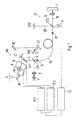
- the interferometric measuring device shown in Fig. 1 has one essential Part of a modulation interferometer arrangement MI, in which one temporal path difference of a reference beam 4 is generated, and a demodulation interferometer arrangement DI, in the one on the surface of a measurement object 7 reflected measuring beam 18 with the reference beam 4 or components brought to interference and the interfered beam to a photodetector 11 is supplied.
- a modulation interferometer arrangement MI in which one temporal path difference of a reference beam 4 is generated
- DI demodulation interferometer arrangement in the one on the surface of a measurement object 7 reflected measuring beam 18 with the reference beam 4 or components brought to interference and the interfered beam to a photodetector 11 is supplied.
- the modulation interferometer arrangement MI is from a light source 1 a collimator 2 is fed an input beam with a first beam splitter ST1 is divided into the reference beam 4 and a second sub-beam 3.
- the Reference beam 4 and the second sub-beam 3 pass through two assigned arms the modulation interferometer arrangement MI, the arm of the reference beam 4 arranged one after the other a mirror SP1, a compensation grating C1, a parallel displacement arrangement of a first and a second has acousto-optical deflector 8.9 and a retro grating 10.
- the two acousto-optical deflectors 8, 9 are controlled frequency-modulated by means of deflector drivers 12.1, 12.2.
- the deflection angle of the reference beam 4 in the first acousto-optical deflector 8 is varied by an angle a by the frequency modulation.
- the reference beam 4 is then deflected again in the direction in which it strikes the first acousto-optical deflector 8. In this way, there is a parallel offset of the reference beam 4 emerging from the second acousto-optical deflector 9, which subsequently illuminates the retro grating 10.
- the retro grating 10 is inclined at a certain angle so that the bent-back reference beam 4, regardless of the parallel offset via the two acousto-optical deflectors 8, 9, the compensation grating C1 and the mirror SP1 returns to the first beam splitter ST1.
- the second arm of the modulation interferometer arrangement MI are in the beam path of the second partial beam 3 a further mirror SP2, one after the other another compensation grid C2 and finally another retro grid 10 'arranged.
- the compensation grid C1 and the further compensation grid C2 on the one hand and the retro grid 10 and the further retro grid 10 'on the other hand are the same.
- the optical lengths of both arms of the modulation interferometer arrangement MI are unequal with a difference that is essential is greater than the coherence length of the light source 1 (e.g. a few mm).
- the compensation grid C1 provides some compensation for the spatial Decoherence of the wave fronts and the angular dispersion caused by the different Wavelengths of the required for the short coherence length Light are achieved.
- the additional dispersion caused, however, with the distance between the retro grid 10 and the compensation grid C1 increases sharply due to the corresponding grids of the other Arms of the modulation interferometer arrangement MI compensated. Because the optical The lengths of both arms are unequal and the returning reference beam interfere 4 and the second partial beam 3 at the output of the modulation interferometer arrangement MI not.
- the demodulation interferometer arrangement DI is connected.
- the demodulation interferometer arrangement DI are in turn behind second beam splitter ST2 two arms formed, in which the two from the intermediate beam 5 partial beams formed are directed.
- the one partial beam falls as Measuring beam 18 via a focusing lens 6 on the surface of the measurement object 7 and is reflected back onto the second beam splitter there.
- the other beam falls on a third mirror SP3, from where it also falls on the second Beam splitter ST2 is returned.
- the compensation measures described above can Light sources with a shorter coherence length can be used, creating a sharper Signal maximum is obtained, or with the same coherence length can improved contrast can be achieved.
- the demodulation interferometer arrangement is located at the input DI a telescope with which the incoming intermediate beam 5 is expanded to carry out a two-dimensional measurement.
- the photodetector 11 is configured as a CCD camera.
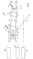
- Fig. 2 shows a further embodiment, the modulation interferometer arrangement MI is compact and doubled Amplitude of the runtime modulation is achieved.
- the light of the short-coherent light source 1 collimated with the collimator 2 and with the first beam splitter ST1 in two Partial beams divided into reference beam 4 and second partial beam 3 correspond to FIG. 1.
- the two partial beams 3, 4 are separated into the both compensation gratings C1 and C2 diffracted and pass through two acousto-optical Modulators 17.1 and 17.2.
- the acousto-optical modulators 17.1, 17.2 are minimal using the assigned modulator driver 16.1,16.2 different frequencies (e.g. 500 kHz), which means that Frequency shift of the two beams for heterodyne interferometric evaluation is enforced.
- only one can the partial beams 3, 4 pass through an acousto-optical modulator.
- both partial beams 3, 4 pass through the two acousto-optical ones Deflectors 8.9 offset in parallel.
- the two acousto-optical deflectors 8.9 are controlled with an identical signal by means of a deflector driver 12, and as a result the two partial beams 3, 4 each become parallel, in time of the control signal, shifted and assigned to respectively assigned retro grids 10, 10 ' from which they are bent back.
- the two retro grids are like this tilted that the simultaneous linear displacement of the partial beams by the acousto-optical deflectors 8.9 an opposing modulation of the transit time causes.
- the retro grids 10, 10 ' are arranged so that for both Partial beams 3,4 the optical path difference according to the embodiment 1 arises.
- the two partial beams 3, 4 after running back over the compensation gratings C1, C2 in the first beam splitter ST1 superimposed, but do not interfere due to the path difference, and passed as an intermediate beam 5 in the demodulation interferometer arrangement, the is preferably designed as a measuring probe.
Landscapes
- Physics & Mathematics (AREA)
- General Physics & Mathematics (AREA)
- Chemical & Material Sciences (AREA)
- Dispersion Chemistry (AREA)
- Instruments For Measurement Of Length By Optical Means (AREA)
- Length Measuring Devices By Optical Means (AREA)
Claims (14)
- Dispositif de mesure interférométrique pour le mesurage de formes sur des surfaces rugueuses d'un objet de mesure (7), comportant une unité de génération de faisceau (1), qui émet un faisceau d'entrée de cohérence courte, un dispositif séparateur de faisceau (ST1, ST2), permettant de former un faisceau de référence (4) dirigé sur un dispositif (8, 9) comportant un élément réfléchissant (10) destiné à la modification périodique de la trajectoire lumineuse, et un faisceau de mesure (18) dirigé sur l'objet de mesure (7), avec un élément de superposition (ST2) au niveau duquel interfèrent entre eux le faisceau de référence (4) provenant de l'objet de mesure (18) et celui provenant du dispositif (8, 9, 10), et comportant un photo-détecteur (11) qui reçoit le faisceau interféré et le dirige vers un dispositif d'exploitation (13),
dans lequel en outre
un dispositif d'interférométrie de modulation (MI) est conçu de telle sorte qu'un premier séparateur de faisceau (ST1) du dispositif séparateur de faisceau, forme en plus du faisceau de référence (4) un deuxième faisceau partiel (3),
le dispositif (8, 9, 10) permettant de modifier la trajectoire lumineuse est un dispositif de déplacement parallèle disposé au moins dans le chemin optique du faisceau de référence (4) et l'élément réfléchissant est une rétro-grille (10),
une grille de compensation (C1) disposée dans le chemin optique du faisceau de référence avant le dispositif de déplacement parallèle (8, 9), dévie le faisceau de référence (4), à la fois avant et après le passage à travers le dispositif de déplacement parallèle (8, 9),
dans le chemin optique du deuxième faisceau partiel (3) est disposé un couple d'éléments identique à celui disposé dans le chemin optique du faisceau de référence (4), composé d'une autre grille de compensation (C2) et d'une rétro-grille (10') disposée en aval de celle-ci, les longueurs de trajectoire optiques des deux bras ainsi formés pour le faisceau de référence (4) et le deuxième faisceau partiel (3) du dispositif d'interférométrie de modulation (MI) présentant une différence supérieure à la longueur de cohérence,
le faisceau de référence (4) renvoyé par le biais de la grille de compensation (C1) et le deuxième faisceau partiel (3) renvoyé par le biais de la grille de compensation (C2) sont assemblés pour former un faisceau intermédiaire (5), et
un dispositif d'interférométrie de démodulation (DI) est configuré de telle sorte que
le faisceau intermédiaire (5) est divisé en deux autres bras du dispositif d'interférométrie de démodulation (DI) au moyen d'un autre séparateur de faisceau (ST2), le premier bras étant terminé par un miroir (SP3) et l'autre bras étant terminé par la surface de l'objet de mesure (7), les deux autres bras présentant la même différence de trajectoire que les bras du dispositif d'interférométrie de modulation (MI), et
les faisceaux renvoyés au niveau du miroir (3) et de la surface de l'objet de mesure (7) interfèrent entre eux au niveau de l'élément de superposition (ST2). - Dispositif de mesure selon la revendication 1,
dans lequel
le dispositif de déplacement parallèle présente un dispositif déflecteur (8, 9) acoustique-optique disposé dans chemin optique, et
le dispositif déflecteur (8, 9) est commandé par modulation de fréquence et est disposé par rapport au faisceau de référence (4) incident et par rapport à la grille réfléchissante (10) de telle sorte que le faisceau de référence (4) envoyé vers l'élément de superposition (ST2), en raison de sa diffraction dans le dispositif déflecteur (8, 9), subit une modification de sa trajectoire lumineuse. - Dispositif de mesure selon la revendication 2,
dans lequel
la constante de grille de la grille de compensation (C1) et de la deuxième grille de compensation (C2) est deux fois plus importante que la constante de grille de la rétro-grille (10) ou de l'autre rétro-grille (10'). - Dispositif de mesure selon la revendication 2 ou 3,
dans lequel
la grille de compensation (C1) et la rétro-grille (10) ainsi que l'autre grille de compensation (C2) et l'autre rétro-grille (10') sont respectivement disposées parallèlement les unes par rapport aux autres. - Dispositif de mesure selon l'une des revendications précédentes,
dans lequel
les grilles de compensation (C1, C2) sont configurées de façon réfléchissante, et
dans le chemin optique du faisceau de référence (4), entre le premier séparateur de faisceau (ST1) et les grilles de compensation (C1, C2), est respectivement disposé un miroir (SP1, SP2), qui renvoie le faisceau de référence (4) ou le deuxième faisceau partiel (3) à l'aller vers la grille de compensation (C1, C2) associée et au retour vers le séparateur de faisceau (ST1) qui génère le faisceau intermédiaire (5). - Dispositif de mesure selon l'une des revendications précédentes,
dans lequel
l'autre séparateur de faisceau (ST2) forme dans le même temps l'élément de superposition. - Dispositif de mesure selon l'une des revendications précédentes,
dans lequel
le dispositif d'interférométrie de démodulation (DI) est relié au dispositif d'interférométrie de modulation (MI) par le biais d'un conducteur de lumière (19). - Dispositif de mesure selon l'une des revendications précédentes,
dans lequel
le faisceau intermédiaire (5) est élargi, à l'entrée du dispositif .. d'interférométrie de démodulation (DI), par un dispositif de télescope, afin de former un faisceau lumineux large, et le photo-détecteur (11) est une caméra CCD. - Dispositif de mesure selon l'une des revendications précédentes,
dans lequel
une structure est prévue pour une exploitation interférométrique hétérodyne connue en soi, avec un dispositif pour le décalage de fréquence entre les faisceaux qui interfèrent entre eux. - Dispositif de mesure selon l'une des revendications précédentes,
dans lequel
le dispositif de déplacement parallèle (8, 9) est disposé uniquement dans le bras du dispositif d'interférométrie de modulation (MI) conduisant le faisceau de référence (4). - Dispositif de mesure selon l'une des revendications 1 à 9,
dans lequel
le dispositif de déplacement parallèle (8, 9) est disposé dans les deux bras du dispositif d'interférométrie de modulation (MI), de telle sorte qu'il est traversé à la fois à l'aller et au retour par le faisceau de référence (4) et par le deuxième faisceau partiel (3). - Dispositif de mesure selon la revendication 11,
dans lequel
la rétro-grille (10) pour le faisceau de référence (4) et l'autre rétro-grille (10') pour le deuxième faisceau partiel (3) sont basculées de telle sorte que le décalage simultané du faisceau de référence (4) et du deuxième faisceau partiel (3) provoque une modulation opposée de leur durée, et les deux rétro-grilles (10, 10') sont disposées de telle sorte que pour le faisceau de référence (4) et le deuxième faisceau partiel (3), on obtient la différence de trajectoire optique. - Dispositif de mesure selon la revendication 11 ou 12,
dans lequel
entre les deux grilles de compensation (C1, C2) et le dispositif de déplacement parallèle est respectivement disposé un modulateur acoustique-optique (17.1, 17.2), et
les modulateurs acoustiques-optiques (17.1, 17.2), pour la génération d'un décalage de fréquence du faisceau de référence (4) et du deuxième faisceau partiel (3), sont commandés avec une fréquence légèrement différente au moyen de pilotes de modulateur associés (16.1, 16.2). - Dispositif de mesure selon la revendication 11 ou 12,
dans lequel
un seul modulateur acoustique-optique est prévu dans l'un des deux bras du dispositif d'interférométrie de modulation (MI), sur le côté du dispositif de déplacement parallèle opposé aux rétro-grilles (10, 10').
Applications Claiming Priority (3)
| Application Number | Priority Date | Filing Date | Title |
|---|---|---|---|
| DE19738900A DE19738900B4 (de) | 1997-09-05 | 1997-09-05 | Interferometrische Meßvorrichtung zur Formvermessung an rauhen Oberflächen |
| DE19738900 | 1997-09-05 | ||
| PCT/DE1998/002564 WO1999013294A1 (fr) | 1997-09-05 | 1998-09-01 | Dispositif de mesure interferometrique pour le mesurage de formes sur des surfaces rugueuses |
Publications (2)
| Publication Number | Publication Date |
|---|---|
| EP0937229A1 EP0937229A1 (fr) | 1999-08-25 |
| EP0937229B1 true EP0937229B1 (fr) | 2004-12-01 |
Family
ID=7841334
Family Applications (1)
| Application Number | Title | Priority Date | Filing Date |
|---|---|---|---|
| EP98951246A Expired - Lifetime EP0937229B1 (fr) | 1997-09-05 | 1998-09-01 | Dispositif de mesure interferometrique pour le mesurage de formes sur des surfaces rugueuses |
Country Status (5)
| Country | Link |
|---|---|
| US (1) | US6064482A (fr) |
| EP (1) | EP0937229B1 (fr) |
| DE (2) | DE19738900B4 (fr) |
| ES (1) | ES2232967T3 (fr) |
| WO (1) | WO1999013294A1 (fr) |
Families Citing this family (6)
| Publication number | Priority date | Publication date | Assignee | Title |
|---|---|---|---|---|
| DE19721884C1 (de) * | 1997-05-26 | 1998-06-04 | Bosch Gmbh Robert | Interferometrische Meßvorrichtung |
| DE10244552B3 (de) * | 2002-09-25 | 2004-02-12 | Robert Bosch Gmbh | Interferometrische Messeinrichtung |
| DE10244553B3 (de) * | 2002-09-25 | 2004-02-05 | Robert Bosch Gmbh | Interferometrische Messeinrichtung |
| DE102004045802B4 (de) | 2004-09-22 | 2009-02-05 | Robert Bosch Gmbh | Interferometrisches System mit Referenzfläche mit einer verspiegelten Zone |
| CN101718520B (zh) * | 2009-11-16 | 2011-01-05 | 浙江大学 | 一种快速表面质量测量系统 |
| CN101949690B (zh) * | 2010-08-24 | 2012-08-22 | 中国科学院光电技术研究所 | 光学面形的检测装置及光学面形的检测方法 |
Citations (1)
| Publication number | Priority date | Publication date | Assignee | Title |
|---|---|---|---|---|
| EP0983483A1 (fr) * | 1997-05-26 | 2000-03-08 | Robert Bosch Gmbh | Dispositif de mesure interferometrique |
Family Cites Families (8)
| Publication number | Priority date | Publication date | Assignee | Title |
|---|---|---|---|---|
| EP0108497B1 (fr) * | 1982-10-08 | 1987-05-13 | National Research Development Corporation | Système de sonde à rayonnement |
| US4848908A (en) * | 1983-10-24 | 1989-07-18 | Lockheed Missiles & Space Company, Inc. | Optical heterodyne roughness measurement system |
| JPH0287005A (ja) * | 1988-09-26 | 1990-03-27 | Brother Ind Ltd | 光ヘテロダイン干渉表面形状測定装置 |
| US5064257A (en) * | 1990-04-06 | 1991-11-12 | Hamamatsu Photonics K.K. | Optical heterodyne scanning type holography device |
| CH693968A5 (de) * | 1993-04-21 | 2004-05-14 | Fraunhofer Ges Forschung | Verfahren und Vorrichtung fuer die Topographiepruefung von Oberflaechen. |
| DE19522262C2 (de) * | 1995-06-20 | 1997-05-22 | Zeiss Carl Jena Gmbh | Heterodyn-Interferometer-Anordnung |
| DE19721843C1 (de) * | 1997-05-26 | 1999-02-11 | Bosch Gmbh Robert | Interferometrische Meßvorrichtung |
| DE19721842C2 (de) * | 1997-05-26 | 1999-04-01 | Bosch Gmbh Robert | Interferometrische Meßvorrichtung |
-
1997
- 1997-09-05 DE DE19738900A patent/DE19738900B4/de not_active Expired - Fee Related
-
1998
- 1998-09-01 ES ES98951246T patent/ES2232967T3/es not_active Expired - Lifetime
- 1998-09-01 US US09/297,695 patent/US6064482A/en not_active Expired - Fee Related
- 1998-09-01 DE DE59812331T patent/DE59812331D1/de not_active Expired - Lifetime
- 1998-09-01 WO PCT/DE1998/002564 patent/WO1999013294A1/fr not_active Ceased
- 1998-09-01 EP EP98951246A patent/EP0937229B1/fr not_active Expired - Lifetime
Patent Citations (1)
| Publication number | Priority date | Publication date | Assignee | Title |
|---|---|---|---|---|
| EP0983483A1 (fr) * | 1997-05-26 | 2000-03-08 | Robert Bosch Gmbh | Dispositif de mesure interferometrique |
Also Published As
| Publication number | Publication date |
|---|---|
| WO1999013294A1 (fr) | 1999-03-18 |
| DE59812331D1 (de) | 2005-01-05 |
| ES2232967T3 (es) | 2005-06-01 |
| EP0937229A1 (fr) | 1999-08-25 |
| DE19738900B4 (de) | 2005-07-14 |
| US6064482A (en) | 2000-05-16 |
| DE19738900A1 (de) | 1999-03-18 |
Similar Documents
| Publication | Publication Date | Title |
|---|---|---|
| DE68914472T2 (de) | Verfahren und Gerät zur Messung von Vibrationen. | |
| DE19721843C1 (de) | Interferometrische Meßvorrichtung | |
| EP1923673B1 (fr) | Dispositif de mesure de position | |
| DE2003492A1 (de) | Messverfahren fuer Schrittgeber zum Messen von Laengen oder Winkeln sowie Anordnungen zur Durchfuehrung dieses Messverfahrens | |
| DE19930687B4 (de) | Optisches Verschiebungsmeßsystem | |
| DE19721882C2 (de) | Interferometrische Meßvorrichtung | |
| DE19721881C2 (de) | Interferometrische Meßvorrichtung | |
| DE4400680C2 (de) | Vorrichtung zur Bestimmung von Abstandsänderungen eines Objekts | |
| DE19628200A1 (de) | Vorrichtung und Verfahren zur Durchführung interferometrischer Messungen | |
| EP0112399B1 (fr) | Méthode de mesure interférométrique pour des surfaces | |
| EP0491749B1 (fr) | Dispositif de mesure de position absolue sur deux dimensions | |
| EP0937229B1 (fr) | Dispositif de mesure interferometrique pour le mesurage de formes sur des surfaces rugueuses | |
| DE19721842C2 (de) | Interferometrische Meßvorrichtung | |
| DE69421877T2 (de) | Lasersonde für Geschwindigkeits- und Neigungsmessung | |
| DE3730091A1 (de) | Interferometrisches distanzmessgeraet | |
| EP0610374B1 (fr) | Procede pour la mesure des inclinaisons d'interfaces dans un systeme optique | |
| DE102005042954B4 (de) | Vorrichtung und Verfahren zur Bestimmung von Geschwindigkeitsprofilen in beliebig gerichteten Strömungen | |
| DE102017219125A1 (de) | Optische Positionsmesseinrichtung | |
| DE69206297T2 (de) | Optischer Spannungsdetektor. | |
| DE69315680T2 (de) | Interferometrische sonde für abstandsmessung | |
| DE19721883C2 (de) | Interferometrische Meßvorrichtung | |
| DE19721884C1 (de) | Interferometrische Meßvorrichtung | |
| EP3742956B1 (fr) | Procédé de production d'un interférogramme bidimensionnel au moyen d'un interféromètre à faisceau libre de type michelson | |
| DE3816755C3 (de) | Vorrichtung zum berührungslosen Erfassen der durch Ultraschallwellen verursachten Oberflächenauslenkung eines Prüflings | |
| DE69122656T2 (de) | Vorrichtung und Verfahren zur Erfassung einer Information über die Verschiebung eines Gegenstands. |
Legal Events
| Date | Code | Title | Description |
|---|---|---|---|
| PUAI | Public reference made under article 153(3) epc to a published international application that has entered the european phase |
Free format text: ORIGINAL CODE: 0009012 |
|
| AK | Designated contracting states |
Kind code of ref document: A1 Designated state(s): DE ES FR GB IT |
|
| 17P | Request for examination filed |
Effective date: 19990920 |
|
| GRAP | Despatch of communication of intention to grant a patent |
Free format text: ORIGINAL CODE: EPIDOSNIGR1 |
|
| GRAS | Grant fee paid |
Free format text: ORIGINAL CODE: EPIDOSNIGR3 |
|
| GRAA | (expected) grant |
Free format text: ORIGINAL CODE: 0009210 |
|
| AK | Designated contracting states |
Kind code of ref document: B1 Designated state(s): DE ES FR GB IT |
|
| REG | Reference to a national code |
Ref country code: GB Ref legal event code: FG4D Free format text: NOT ENGLISH |
|
| REF | Corresponds to: |
Ref document number: 59812331 Country of ref document: DE Date of ref document: 20050105 Kind code of ref document: P |
|
| REG | Reference to a national code |
Ref country code: ES Ref legal event code: FG2A Ref document number: 2232967 Country of ref document: ES Kind code of ref document: T3 |
|
| GBT | Gb: translation of ep patent filed (gb section 77(6)(a)/1977) |
Effective date: 20050518 |
|
| ET | Fr: translation filed | ||
| PLBE | No opposition filed within time limit |
Free format text: ORIGINAL CODE: 0009261 |
|
| STAA | Information on the status of an ep patent application or granted ep patent |
Free format text: STATUS: NO OPPOSITION FILED WITHIN TIME LIMIT |
|
| 26N | No opposition filed |
Effective date: 20050902 |
|
| PGFP | Annual fee paid to national office [announced via postgrant information from national office to epo] |
Ref country code: ES Payment date: 20090928 Year of fee payment: 12 |
|
| PGFP | Annual fee paid to national office [announced via postgrant information from national office to epo] |
Ref country code: GB Payment date: 20090922 Year of fee payment: 12 |
|
| PGFP | Annual fee paid to national office [announced via postgrant information from national office to epo] |
Ref country code: DE Payment date: 20091120 Year of fee payment: 12 |
|
| PGFP | Annual fee paid to national office [announced via postgrant information from national office to epo] |
Ref country code: IT Payment date: 20090924 Year of fee payment: 12 |
|
| GBPC | Gb: european patent ceased through non-payment of renewal fee |
Effective date: 20100901 |
|
| PG25 | Lapsed in a contracting state [announced via postgrant information from national office to epo] |
Ref country code: IT Free format text: LAPSE BECAUSE OF NON-PAYMENT OF DUE FEES Effective date: 20100901 |
|
| REG | Reference to a national code |
Ref country code: FR Ref legal event code: ST Effective date: 20110531 |
|
| REG | Reference to a national code |
Ref country code: DE Ref legal event code: R119 Ref document number: 59812331 Country of ref document: DE Effective date: 20110401 |
|
| PG25 | Lapsed in a contracting state [announced via postgrant information from national office to epo] |
Ref country code: FR Free format text: LAPSE BECAUSE OF NON-PAYMENT OF DUE FEES Effective date: 20100930 Ref country code: DE Free format text: LAPSE BECAUSE OF NON-PAYMENT OF DUE FEES Effective date: 20110401 |
|
| PG25 | Lapsed in a contracting state [announced via postgrant information from national office to epo] |
Ref country code: GB Free format text: LAPSE BECAUSE OF NON-PAYMENT OF DUE FEES Effective date: 20100901 |
|
| PGFP | Annual fee paid to national office [announced via postgrant information from national office to epo] |
Ref country code: FR Payment date: 20091005 Year of fee payment: 12 |
|
| REG | Reference to a national code |
Ref country code: ES Ref legal event code: FD2A Effective date: 20111019 |
|
| PG25 | Lapsed in a contracting state [announced via postgrant information from national office to epo] |
Ref country code: ES Free format text: LAPSE BECAUSE OF NON-PAYMENT OF DUE FEES Effective date: 20100902 |