EP0937305B1 - Schaltersystem in mid-technik - Google Patents
Schaltersystem in mid-technik Download PDFInfo
- Publication number
- EP0937305B1 EP0937305B1 EP97911184A EP97911184A EP0937305B1 EP 0937305 B1 EP0937305 B1 EP 0937305B1 EP 97911184 A EP97911184 A EP 97911184A EP 97911184 A EP97911184 A EP 97911184A EP 0937305 B1 EP0937305 B1 EP 0937305B1
- Authority
- EP
- European Patent Office
- Prior art keywords
- housing
- switch system
- fact
- cover
- adapter
- Prior art date
- Legal status (The legal status is an assumption and is not a legal conclusion. Google has not performed a legal analysis and makes no representation as to the accuracy of the status listed.)
- Expired - Lifetime
Links
- 238000000034 method Methods 0.000 title abstract description 3
- 239000004020 conductor Substances 0.000 claims abstract description 12
- 239000000463 material Substances 0.000 claims 1
- 239000007787 solid Substances 0.000 claims 1
- 238000005516 engineering process Methods 0.000 abstract description 11
- 230000008901 benefit Effects 0.000 description 4
- 230000004907 flux Effects 0.000 description 3
- 239000004033 plastic Substances 0.000 description 3
- 239000000969 carrier Substances 0.000 description 2
- 238000005192 partition Methods 0.000 description 2
- 238000005476 soldering Methods 0.000 description 2
- 238000004026 adhesive bonding Methods 0.000 description 1
- 230000000712 assembly Effects 0.000 description 1
- 238000000429 assembly Methods 0.000 description 1
- 230000008859 change Effects 0.000 description 1
- 238000010276 construction Methods 0.000 description 1
- 238000002347 injection Methods 0.000 description 1
- 239000007924 injection Substances 0.000 description 1
- 238000004519 manufacturing process Methods 0.000 description 1
- 239000002991 molded plastic Substances 0.000 description 1
- 230000000149 penetrating effect Effects 0.000 description 1
- 230000000284 resting effect Effects 0.000 description 1
- 229910000679 solder Inorganic materials 0.000 description 1
- 238000003860 storage Methods 0.000 description 1
- 238000003466 welding Methods 0.000 description 1
Images


Classifications
-
- H—ELECTRICITY
- H01—ELECTRIC ELEMENTS
- H01H—ELECTRIC SWITCHES; RELAYS; SELECTORS; EMERGENCY PROTECTIVE DEVICES
- H01H1/00—Contacts
- H01H1/58—Electric connections to or between contacts; Terminals
-
- B—PERFORMING OPERATIONS; TRANSPORTING
- B29—WORKING OF PLASTICS; WORKING OF SUBSTANCES IN A PLASTIC STATE IN GENERAL
- B29L—INDEXING SCHEME ASSOCIATED WITH SUBCLASS B29C, RELATING TO PARTICULAR ARTICLES
- B29L2031/00—Other particular articles
- B29L2031/34—Electrical apparatus, e.g. sparking plugs or parts thereof
- B29L2031/3493—Moulded interconnect devices, i.e. moulded articles provided with integrated circuit traces
-
- H—ELECTRICITY
- H01—ELECTRIC ELEMENTS
- H01H—ELECTRIC SWITCHES; RELAYS; SELECTORS; EMERGENCY PROTECTIVE DEVICES
- H01H11/00—Apparatus or processes specially adapted for the manufacture of electric switches
- H01H11/0006—Apparatus or processes specially adapted for the manufacture of electric switches for converting electric switches
-
- H—ELECTRICITY
- H01—ELECTRIC ELEMENTS
- H01H—ELECTRIC SWITCHES; RELAYS; SELECTORS; EMERGENCY PROTECTIVE DEVICES
- H01H1/00—Contacts
- H01H1/58—Electric connections to or between contacts; Terminals
- H01H2001/5888—Terminals of surface mounted devices [SMD]
-
- H—ELECTRICITY
- H01—ELECTRIC ELEMENTS
- H01H—ELECTRIC SWITCHES; RELAYS; SELECTORS; EMERGENCY PROTECTIVE DEVICES
- H01H11/00—Apparatus or processes specially adapted for the manufacture of electric switches
- H01H11/04—Apparatus or processes specially adapted for the manufacture of electric switches of switch contacts
- H01H11/06—Fixing of contacts to carrier ; Fixing of contacts to insulating carrier
- H01H2011/065—Fixing of contacts to carrier ; Fixing of contacts to insulating carrier by plating metal or conductive rubber on insulating substrate, e.g. Molded Interconnect Devices [MID]
-
- H—ELECTRICITY
- H01—ELECTRIC ELEMENTS
- H01H—ELECTRIC SWITCHES; RELAYS; SELECTORS; EMERGENCY PROTECTIVE DEVICES
- H01H13/00—Switches having rectilinearly-movable operating part or parts adapted for pushing or pulling in one direction only, e.g. push-button switch
- H01H13/02—Details
- H01H13/023—Light-emitting indicators
- H01H2013/026—Light-emitting indicators with two or more independent lighting elements located inside the push button switch that illuminate separate zones of push buttons
-
- H—ELECTRICITY
- H01—ELECTRIC ELEMENTS
- H01H—ELECTRIC SWITCHES; RELAYS; SELECTORS; EMERGENCY PROTECTIVE DEVICES
- H01H2219/00—Legends
- H01H2219/036—Light emitting elements
- H01H2219/04—Attachments; Connections
-
- H—ELECTRICITY
- H01—ELECTRIC ELEMENTS
- H01H—ELECTRIC SWITCHES; RELAYS; SELECTORS; EMERGENCY PROTECTIVE DEVICES
- H01H2219/00—Legends
- H01H2219/054—Optical elements
- H01H2219/064—Optical isolation of switch sites
-
- H—ELECTRICITY
- H01—ELECTRIC ELEMENTS
- H01H—ELECTRIC SWITCHES; RELAYS; SELECTORS; EMERGENCY PROTECTIVE DEVICES
- H01H23/00—Tumbler or rocker switches, i.e. switches characterised by being operated by rocking an operating member in the form of a rocker button
- H01H23/02—Details
- H01H23/025—Light-emitting indicators
Definitions
- the invention relates to a switch system using MID technology.
- Several conductor layers can be used be encapsulated within the housing. But it can also plastic-like plastic structures cast into a housing be, which subsequently metallize and insulate.
- the conductor tracks run in this way on the housing surface extending in three spatial directions (3D). Further details on this can be found in the magazine "Electronics", year 15, dated July 20, 1990 (Page 28 - 31).
- An advertisement provides further information the research association of spatial electronic assemblies 3-D MID e.V ..
- the present invention is concerned with the application of these techniques to a switch system, especially in the field of automotive engineering.
- switches Due to the constantly growing number of electrical and electronic working driving aids in motor vehicles is also the The need for switches has grown.
- Conventional type switches essentially consist of button, housing, contact system, mechanical detent, base plate and contact plug. aim the invention is to simplify the construction of such switches and at the same time reduce the spatial dimensions.
- the housing according to the invention uses the possibilities of the MID technology in so far as simultaneously the connector is designed as a molded plastic part is, the plastic serving as a connector projections are metallized.
- Circuit changes can also be made through such plated-through holes in the switch system by some Contact openings are made conductive while the others have no conductive connection.
- microswitches can be selected in this way be that they close a circuit when they are operated or open one circuit or another Switch over the circuit or when several are actuated perform these operations simultaneously.
- These different Microswitch types can be used multiple times in the housing according to the invention used and combined with each other become. But it is also possible to add one Microswitch or an LED instead of a microswitch use that either in automotive engineering Driver the position of the switch (in the dark) or the condition of the switch (on or off).
- the housing according to the invention can also be used in this way be equipped that no microswitch is provided at all is and that the housing only by means of the LED display functions takes over.
- the microswitch manually or can be operated directly by mechanical actuators or that the display area directly through the surface of the housing according to the invention is formed.
- the electrical circuit on the surface of the case protect or cover for aesthetic reasons.
- Claim 3 So a cap is placed on the housing, which shields the wiring on the housing and before protects mechanical access. This can, for example by using lenses in the cap or windows that can in turn be provided with symbols, the operator help of the vehicle.
- a simple type of actuation on the housing surface applied microswitch can be by the application achieve the features of claim 4.
- the cap serves as a button for the switch, the cap in turn manually or can also be operated mechanically. It is however, to be taken into account that different for the switching path Claims are to be made.
- the button of a pressure switch a comparatively small actuation path is sufficient. The same applies if the circuit is only operated for as long should be when a button is pressed becomes.
- it may be desirable that the position of the button is also an indication of the Switching state of the switch is given. For example in the case of a pressure switch, the depth of the Pushbutton or, in the case of a toggle switch, the toggle position of the button his.
- the cap should be tiltable relative to the adapter and the housing be, it is recommended in further development of the invention Combination of features according to claim 6 Set the fulcrum as high as possible so that the cap is in place maximum possible angle of rotation is reached before it on the Housing strikes.
- the Cap itself is made in MID technology and thus as a movable Switching element works. It can both as Switch piece work in a push button, but also as Tilting contact in a toggle switch. These switching functions can in addition to operating the on the Housing microswitch or instead of this microswitch to get voted.
- a particularly simple resting possibility results from the choice of features according to claim 8 Detent positions essentially specified by the adapter, so that by choosing an appropriate adapter desired rest positions can be achieved without the Replace cap.
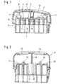
- a housing 1 is shown, which in MID technology is made. That means that within the cast Housing the conductor tracks and electrical connections already poured or worked out on the surface are.
- the housing 1 has on the inside of the housing or housing top 2 at least one flat placement surface 3, on which components in SMD technology (Surface Mounted Device) put on by soldering machines can be.
- Microswitches 4 are the components here and an LED 5 is provided.
- the housing has molded projections on its underside 6, whose surface as an electrically conductive conductor tracks are designed so that the projections 6 in their Act as a plug. Are still on the housing 1 Stops 8 to limit the tilting movement of a cap 9 provided, which one about the pivot pin 10 is not closer shown pivot bearing is pivotable. In the cap 9 is a window 11 inserted through which the luminous flux of LED 5 is recognizable. On the cap 9 is still on the surface a grip surface 12 incorporated.
- FIG. 2 shows a somewhat modified version of the housing 1, the changes being used to match the shape of the case Adapt the shape of common switches.
- FIG Cap 9 snapped onto the housing 1 (see also FIG. 3) and is thus rigidly connected to the housing 1.
- the Housing has two windows 13, 14, which are suitable inserted into the cap or cast into it can.
- the luminous flux radiates through these windows 13, 14 LEDs 15,16, which on the assembly areas 17,18 in SMD technology are put on.
- the placement areas are 17, 18 put up to use machines when loading can reach the non-deep assembly areas can.
- the cap 9 in Fig. 2 has a partition 19 which the Luminous flux of the two LEDs 15, 16 separates from one another. It is but also possible that an additional one on the housing 1 Diode is arranged on a base 20, however here two partitions must be provided.
- Fig. 3 shows a partially sectioned front view of the 2, wherein it can be clearly seen that the cap snapped onto the housing 1 via latches 21, 22 is.
- the cap 9 according to FIG. 2 is via a rotary bearing 23 tiltably attached to the housing. This can be done on the housing corresponding side walls must be raised. It an adapter according to FIG. 6 can also be used which will be explained in more detail below.
- Out 4 are also holes penetrating the wall of the housing 24 to recognize which are used for the plated-through hole and thus the conductor tracks on the top of the housing 2 connect the bottom of the housing 25. That way you can the connections for microswitch diodes or other electrical Components with the projections acting as plug 7 6 can be connected.
- Fig. 5 shows the housing of FIG. 4, with a latching circuit is provided.
- the housing 1 is with a Locking curve 27 provided on the one in the cap 9 resilient stored locking pin 28 acts.
- FIG. 6 shows the housing illustration according to FIG. 4, however an adapter 29 was used.
- the adapter has that Task, the pivot point of the cap over the placement level 2 of the housing. In this way it is possible on the one hand to keep the case comparatively flat, if it is required purely for display purposes according to FIG. 2.
- the placement machine moving over the housing dives down to lower assembly areas.
- the assembly areas should therefore in terms of the housing the top level. In this case it would be not possible without the adapter the pivot point of the cap over the To move assembly level beyond.
- the assembly is made first and then the adapter with the cap on the assembled housing.
- the latches are 21,22 identical for the adapter and the cap 9, so that instead of the cap 9 in FIG. 3, the adapter 29 into the catches 21.22 can be used.
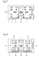
- Fig. 7 shows a top view of the housing and specifically the assembly surfaces 3 of the top of the housing 2.
- the prepared soldering points 31, which are used as connection points serve for electrical components.
- the toggle switch only with a central LED 36 located on the base is provided while the two LEDs 15, 16 disappear.
- 7 and 8 also show the possibility of microswitches of different types and Arrange shape on the placement surface 3, so that this Micro switches optionally equipped in any combination can be.
Landscapes
- Physics & Mathematics (AREA)
- Electromagnetism (AREA)
- Switch Cases, Indication, And Locking (AREA)
- Conductive Materials (AREA)
- Vehicle Step Arrangements And Article Storage (AREA)
- Lock And Its Accessories (AREA)
- Manufacture Of Switches (AREA)
- Tumbler Switches (AREA)
- Contacts (AREA)
Abstract
Description
- Fig. 1
- eine erste Ausführungsform des erfindungsgemäßen Gehäuses mit einer kippbaren Kappe,
- Fig. 2
- eine höhergezogene Gehäuseform mit einer fest aufgerasteten Kappe,
- Fig. 3
- das Gehäuse nach Fig. 3 in Frontansicht,
- Fig. 4
- das Gehäuse nach Fig. 2 mit einer kippbaren Kappe,
- Fig. 5
- das Gehäuse nach Fig. 4 mit einer Rastanordnung,
- Fig. 6
- das Gehäuse nach Fig. 4 in geschnittener Frontansicht mit eingesetztem Adapter und darauf montierter kippbarer Kappe,
- Fig. 7
- eine Draufsicht auf das Gehäuse nach Fig. 2 mit zur Bestückung vorbereiteten Lötkontakten und
- Fig. 8
- die Gehäuseansicht nach Fig. 7 mit Bestückung durch LED's und Mikroschaltern.
Claims (12)
- Schaltersystem mit einem Gehäuse (1), welches als räumlich spritzgegossener Leitungsträger (MID) ausgestaltet ist, dadurch gekennzeichnet, daß auf der Gehäuseinnenseite bzw. Gehäuseoberseite (2) mindestens eine ebene Bestückungsfläche (3) vorgesehen ist, auf der mechanische und/oder elektrische Bauelemente (15,16,32-36) aufgesetzt sind und daß auf der Gehäuseunterseite (25) einstückig angegossene Gehäusevorsprünge (6) vorgesehen sind, welche mit elektrischen Kontakten versehen sind und welche ein Anschlußsteckteil für elektrische Anschlußstecker bilden.
- Schaltersystem nach Anspruch 1, dadurch gekennzeichnet, daß zumindest eines der Bauelemente (15,16,32-36) durch einen Mikroschalter (32-35) oder durch eine LED (15,16,36) gebildet ist.
- Schaltersystem nach einem der vorangegangenen Ansprüche, dadurch gekennzeichnet, daß oberhalb der Gehäuseoberseite (2) eine Kappe (9) angeordnet ist, die vorzugsweise mit mindestens einem durchsichtigen Bereich (13,14,11) versehen ist, welche oberhalb einer LED (15,16,36) angeordnet ist.
- Schaltersystem nach Anspruch 3, dadurch gekennzeichnet, daß die Kappe (9) gegenüber dem Gehäuse (1) bewegbar, insbesondere kippbar angeordnet ist.
- Schaltersystem nach Anspruch 4, dadurch gekennzeichnet, daß zwischen Kappe (9) und Gehäuse (1) ein Adapter (29) eingefügt ist, wobei der Adapter mit dem Gehäuse verrastet (21,22) ist.
- Schaltersystem nach Anspruch 5, dadurch gekennzeichnet, daß die Kappe (9) in dem Adapter über ein Schwenklager (30) drehbar gelagert ist.
- Schaltersystem nach einem der Ansprüche 4 bis 6, dadurch gekennzeichnet, daß der Adapter mit der Kappe eine Rastanordnung (27,28) bildet, die aus einer Rastkurve (27) und einem Rastnocken (28) gebildet ist, die elastisch ineinander greifen.
- Schaltersystem nach Anspruch 7, dadurch gekennzeichnet, daß die Rastkurve in dem Adapter (29) und der Rastnocken (28) durch einen an der Kappe federnd abgestützten Rastbolzen (28) gebildet ist.
- Schaltersystem nach einem der Ansprüche 1 bis 8, dadurch gekennzeichnet, daß die Kappe (9) ebenfalls als spritzgegossener Leitungsträger (MID) ausgestaltet ist.
- Schaltersystem nach einem der Ansprüche 1 bis 9, dadurch gekennzeichnet, daß die Kappe als Schaltwippe eines Kippschalters dient.
- Schaltersystem nach einem der Ansprüche 8 oder 9, dadurch gekennzeichnet, daß in die Kappenfläche eine von der Kappenaußenseite erkennbare Leuchte insbesondere LED eingefügt ist und daß die Stromzufuhr über die Rastverbindung (21,22) bzw. das Schwenklager (30) der Kappe (9) zugeführt ist.
- Schaltersystem nach einem der vorangegangenen Ansprüche, dadurch gekennzeichnet, daß an mechanisch und/oder elektrisch stark belasteten Bereichen den Anforderungen genügende Materialien eingefügt sind.
Applications Claiming Priority (3)
| Application Number | Priority Date | Filing Date | Title |
|---|---|---|---|
| DE19645822 | 1996-11-07 | ||
| DE19645822A DE19645822B4 (de) | 1996-11-07 | 1996-11-07 | Schaltersystem in MID-Technik |
| PCT/EP1997/005496 WO1998020508A1 (de) | 1996-11-07 | 1997-10-07 | Schaltersystem in mid-technik |
Publications (3)
| Publication Number | Publication Date |
|---|---|
| EP0937305A1 EP0937305A1 (de) | 1999-08-25 |
| EP0937305B1 true EP0937305B1 (de) | 2000-07-12 |
| EP0937305B2 EP0937305B2 (de) | 2004-06-30 |
Family
ID=7810860
Family Applications (1)
| Application Number | Title | Priority Date | Filing Date |
|---|---|---|---|
| EP97911184A Expired - Lifetime EP0937305B2 (de) | 1996-11-07 | 1997-10-07 | Schaltersystem in mid-technik |
Country Status (7)
| Country | Link |
|---|---|
| US (1) | US6255610B1 (de) |
| EP (1) | EP0937305B2 (de) |
| JP (1) | JP2001503560A (de) |
| BR (1) | BR9712907A (de) |
| DE (2) | DE19645822B4 (de) |
| ES (1) | ES2147981T3 (de) |
| WO (1) | WO1998020508A1 (de) |
Families Citing this family (24)
| Publication number | Priority date | Publication date | Assignee | Title |
|---|---|---|---|---|
| DE19842333C2 (de) * | 1998-09-16 | 2000-10-19 | Bosch Gmbh Robert | Modul einer elektrohydraulischen Getriebesteuerung |
| DE29905710U1 (de) | 1999-03-22 | 1999-08-12 | Petri Ag, 63743 Aschaffenburg | Elektrischer Schalter für Kraftfahrzeuge |
| DE10121052A1 (de) * | 2001-04-28 | 2002-10-31 | Moeller Gmbh | Strombegrenzender Leistungsschalter |
| DE10142503A1 (de) * | 2001-08-30 | 2003-03-20 | Bsh Bosch Siemens Hausgeraete | Elektrisches Küchengerät |
| DE10231248A1 (de) * | 2002-07-11 | 2004-02-12 | Moeller Gmbh | Auslöseanordnung für ein Kontaktsystem eines Schaltgerätes |
| DE10259605B3 (de) * | 2002-12-19 | 2004-03-18 | Berker Gmbh & Co. Kg | Elektrischer Kippschalter |
| US6720512B1 (en) * | 2003-03-24 | 2004-04-13 | Dan Rothbauer | Surface mount switch plate |
| US7045730B2 (en) * | 2003-12-30 | 2006-05-16 | Symbol Technologies, Inc. | Tamper resistance apparatus for an electrical device and an electrical device including the apparatus |
| US7026564B1 (en) * | 2004-01-27 | 2006-04-11 | Pass & Seymour/Legrand | Paddle switch assembly |
| JP4387821B2 (ja) * | 2004-02-03 | 2009-12-24 | キヤノン株式会社 | 光透過型操作部材および電子機器 |
| KR101054406B1 (ko) * | 2004-03-05 | 2011-08-05 | 엘지전자 주식회사 | 조작 버튼 |
| US7057126B1 (en) * | 2005-05-31 | 2006-06-06 | Sunwave Technology Corp. | Press button light emitting structure |
| JP2007087671A (ja) * | 2005-09-20 | 2007-04-05 | Omron Corp | スイッチ装置 |
| JP2007087672A (ja) * | 2005-09-20 | 2007-04-05 | Omron Corp | スイッチ装置 |
| MA28719B1 (fr) * | 2005-12-02 | 2007-07-02 | Simon Sa | Mecanisme electrique encastrable et plurifonctionnel |
| US7521642B2 (en) * | 2006-02-06 | 2009-04-21 | Toyota Motor Engineering & Manufacturing North America, Inc. | Switch assembly for an automotive power window |
| JP2007220579A (ja) * | 2006-02-20 | 2007-08-30 | Matsushita Electric Ind Co Ltd | 電子装置 |
| TW200809888A (en) * | 2006-08-15 | 2008-02-16 | Asia Optical Co Inc | Apparatus of compound key |
| WO2008131705A1 (de) * | 2007-04-30 | 2008-11-06 | Siemens Aktiengesellschaft | Optische anzeige |
| US7872205B2 (en) * | 2007-05-14 | 2011-01-18 | Lamb Justin J | Electrical switches |
| DE102007037483A1 (de) * | 2007-08-08 | 2009-02-19 | Kromberg & Schubert Gmbh & Co. Kg | Elektronische Baugruppe und Verfahren zu deren Herstellung |
| RU2416872C1 (ru) * | 2009-11-05 | 2011-04-20 | Открытое акционерное общество "Научно-технический центр "Завод Ленинец" (ОАО "НТЦ "Завод Ленинец") | Твердотельный усилитель мощности |
| CN102449860B (zh) * | 2010-06-04 | 2014-09-10 | 丰田自动车株式会社 | 插头装置 |
| KR101660693B1 (ko) * | 2014-11-26 | 2016-09-28 | (주) 오토이노텍 | 전원제어장치 |
Family Cites Families (20)
| Publication number | Priority date | Publication date | Assignee | Title |
|---|---|---|---|---|
| US4480292A (en) * | 1982-03-31 | 1984-10-30 | Emhart Industries, Inc. | Light assembly |
| DE3917637C2 (de) * | 1989-05-31 | 1993-10-07 | Priesemuth W | Mehrfachtastschalter |
| DE9100962U1 (de) * | 1991-01-29 | 1991-04-18 | Mannesmann Kienzle GmbH, 7730 Villingen-Schwenningen | Anordnung einer elektronischen Einrichtung mit mehreren Steckverbindungen |
| US5290983A (en) | 1991-08-02 | 1994-03-01 | The Whitaker Corporation | Wall switch |
| DE9212062U1 (de) * | 1992-09-08 | 1992-10-29 | Abb Patent Gmbh, 68309 Mannheim | Wipptaster |
| DE9212962U1 (de) | 1992-09-25 | 1992-11-19 | Bosch-Siemens Hausgeräte GmbH, 8000 München | Backofen |
| DE9218404U1 (de) * | 1992-10-08 | 1994-01-27 | Siemens AG, 80333 München | Bedienungskörper |
| DE4242100B4 (de) * | 1992-12-14 | 2004-02-05 | Abb Patent Gmbh | Elektrisches Schaltgerät |
| DE4303980B4 (de) * | 1993-02-11 | 2004-03-25 | Rafi Gmbh & Co. Kg Elektrotechnische Spezialfabrik | Netzschalter zur Verbindung elektrischer Kontakte |
| US5412166A (en) | 1993-06-25 | 1995-05-02 | United Technologies Automotive, Inc. | Power window switch control apparatus |
| US5359165A (en) * | 1993-07-16 | 1994-10-25 | Eaton Corporation | Illuminated rotary switch assembly |
| DE4338829C2 (de) * | 1993-11-13 | 1997-12-11 | Daimler Benz Ag | Schaltelementanordnung |
| US5446253A (en) * | 1994-04-21 | 1995-08-29 | Eaton Corporation | Switch actuator assembly |
| DE9411391U1 (de) * | 1994-07-14 | 1995-11-16 | Gira Giersiepen Gmbh & Co Kg, 42477 Radevormwald | Elektro-Installationsgerät |
| DE4426350C2 (de) * | 1994-07-25 | 2001-08-02 | Teves Gmbh Alfred | Schaltersystem mit einem Systemgehäuse |
| DE4439008C2 (de) * | 1994-11-02 | 1999-05-27 | Eaton Controls Gmbh | Elektrischer Tastschalter |
| DE29500869U1 (de) * | 1995-01-20 | 1996-02-22 | Cherry Mikroschalter GmbH, 91275 Auerbach | Bedieneinheit zur Sitzverstellung |
| US5833048A (en) * | 1995-02-07 | 1998-11-10 | Eaton Corporation | Rocker switch especially for vehicles |
| JP3152118B2 (ja) * | 1995-07-27 | 2001-04-03 | オムロン株式会社 | スイッチ装置 |
| JPH09320381A (ja) * | 1996-05-29 | 1997-12-12 | Niles Parts Co Ltd | スイッチのノブ照明装置 |
-
1996
- 1996-11-07 DE DE19645822A patent/DE19645822B4/de not_active Expired - Fee Related
-
1997
- 1997-10-07 US US09/297,788 patent/US6255610B1/en not_active Expired - Fee Related
- 1997-10-07 EP EP97911184A patent/EP0937305B2/de not_active Expired - Lifetime
- 1997-10-07 JP JP52098598A patent/JP2001503560A/ja not_active Ceased
- 1997-10-07 DE DE59702028T patent/DE59702028D1/de not_active Expired - Fee Related
- 1997-10-07 BR BR9712907A patent/BR9712907A/pt unknown
- 1997-10-07 ES ES97911184T patent/ES2147981T3/es not_active Expired - Lifetime
- 1997-10-07 WO PCT/EP1997/005496 patent/WO1998020508A1/de not_active Ceased
Also Published As
| Publication number | Publication date |
|---|---|
| BR9712907A (pt) | 2000-03-21 |
| DE59702028D1 (de) | 2000-08-17 |
| EP0937305B2 (de) | 2004-06-30 |
| EP0937305A1 (de) | 1999-08-25 |
| ES2147981T3 (es) | 2000-10-01 |
| JP2001503560A (ja) | 2001-03-13 |
| WO1998020508A1 (de) | 1998-05-14 |
| DE19645822A1 (de) | 1998-05-14 |
| DE19645822B4 (de) | 2006-07-06 |
| US6255610B1 (en) | 2001-07-03 |
Similar Documents
| Publication | Publication Date | Title |
|---|---|---|
| EP0937305B1 (de) | Schaltersystem in mid-technik | |
| EP0101092B1 (de) | Vorrichtung für elektrische Geräte zur äusseren Eingabe und/oder Anzeige von Informationen | |
| DE4242100B4 (de) | Elektrisches Schaltgerät | |
| DE60305297T2 (de) | Modularer elektrischer schalter und elektrische schaltvorrichtung mit mindestens einem solchen schalter | |
| EP1228285B1 (de) | Elektronische steuerungseinrichtung zur ansteuerung elektrischer aggregate von kraftfahrzeugtüren mit unterschiedlicher ausstattung | |
| WO2010031492A1 (de) | Klemmenkasten zum elektrischen anschluss an einen elektromotor | |
| DE4426350A1 (de) | Schaltersystem mit einem räumlich spritzgegossenen Schaltungsträger | |
| DE102004061528B4 (de) | Kontaktstruktur für einen Schiebeschalter | |
| EP0762449B1 (de) | Wipptaster | |
| EP1282345A2 (de) | Gehäuse zur Aufnahme einer Leiterplatte mit elektronischen Bauteilen in Fahrzeugen | |
| DE3440763A1 (de) | Lenkstockschalter fuer kraftfahrzeuge | |
| DE19803693A1 (de) | Stockschalter, insbesondere Lenkstockschalter für Kraftfahrzeuge | |
| EP0799406A1 (de) | Anzeigeinstrument | |
| DE69308401T2 (de) | Bedienungstafel mit Berührungstasten für die Regelung einer Klimatisiereinrichtung eines Fahrzeuginnenraums | |
| WO2007009574A1 (de) | Mehrstufenschalter | |
| EP0675515B1 (de) | Schalter, insbesondere in die Armaturentafel eines Kraftfahrzeuges einbaubarer Schalter, sowie Verfahren zum Herstellen eines Schalters | |
| DE3728756C1 (en) | Switch block with a plurality of control switches, in particular for a motor vehicle | |
| DE3917637C2 (de) | Mehrfachtastschalter | |
| EP1462296A2 (de) | Lenksäulenmodul | |
| DE4405760A1 (de) | Leuchtmittel sowie beleuchtbarer elektrischer Schalter | |
| DE29905710U1 (de) | Elektrischer Schalter für Kraftfahrzeuge | |
| DE102013211827A1 (de) | Schalter, Verfahren zum Herstellen eines Schalters und Elektronikmodulsystem | |
| EP0576822A1 (de) | Modular Schaltelementblock | |
| DE3928830C2 (de) | ||
| DE10130251C1 (de) | Drucktastenschaltergehäuse und Drucktastenschalter |
Legal Events
| Date | Code | Title | Description |
|---|---|---|---|
| PUAI | Public reference made under article 153(3) epc to a published international application that has entered the european phase |
Free format text: ORIGINAL CODE: 0009012 |
|
| 17P | Request for examination filed |
Effective date: 19990416 |
|
| AK | Designated contracting states |
Kind code of ref document: A1 Designated state(s): DE ES FR GB |
|
| GRAG | Despatch of communication of intention to grant |
Free format text: ORIGINAL CODE: EPIDOS AGRA |
|
| GRAG | Despatch of communication of intention to grant |
Free format text: ORIGINAL CODE: EPIDOS AGRA |
|
| GRAH | Despatch of communication of intention to grant a patent |
Free format text: ORIGINAL CODE: EPIDOS IGRA |
|
| 17Q | First examination report despatched |
Effective date: 19991108 |
|
| GRAH | Despatch of communication of intention to grant a patent |
Free format text: ORIGINAL CODE: EPIDOS IGRA |
|
| GRAA | (expected) grant |
Free format text: ORIGINAL CODE: 0009210 |
|
| AK | Designated contracting states |
Kind code of ref document: B1 Designated state(s): DE ES FR GB |
|
| PG25 | Lapsed in a contracting state [announced via postgrant information from national office to epo] |
Ref country code: ES Free format text: LAPSE BECAUSE OF FAILURE TO SUBMIT A TRANSLATION OF THE DESCRIPTION OR TO PAY THE FEE WITHIN THE PRESCRIBED TIME-LIMIT Effective date: 20000712 |
|
| GBT | Gb: translation of ep patent filed (gb section 77(6)(a)/1977) |
Effective date: 20000712 |
|
| REF | Corresponds to: |
Ref document number: 59702028 Country of ref document: DE Date of ref document: 20000817 |
|
| ET | Fr: translation filed | ||
| REG | Reference to a national code |
Ref country code: ES Ref legal event code: FG2A Ref document number: 2147981 Country of ref document: ES Kind code of ref document: T3 |
|
| PLBQ | Unpublished change to opponent data |
Free format text: ORIGINAL CODE: EPIDOS OPPO |
|
| PLBQ | Unpublished change to opponent data |
Free format text: ORIGINAL CODE: EPIDOS OPPO |
|
| PLBI | Opposition filed |
Free format text: ORIGINAL CODE: 0009260 |
|
| PLBF | Reply of patent proprietor to notice(s) of opposition |
Free format text: ORIGINAL CODE: EPIDOS OBSO |
|
| 26 | Opposition filed |
Opponent name: TRW AUTOMOTIVE ELECTRONICS & COMPONENTS GMBH & CO. Effective date: 20010412 Opponent name: LEOPOLD KOSTAL GMBH & CO. KG Effective date: 20010411 Opponent name: CHERRY GMBH Effective date: 20010412 |
|
| PLBF | Reply of patent proprietor to notice(s) of opposition |
Free format text: ORIGINAL CODE: EPIDOS OBSO |
|
| PLBF | Reply of patent proprietor to notice(s) of opposition |
Free format text: ORIGINAL CODE: EPIDOS OBSO |
|
| REG | Reference to a national code |
Ref country code: GB Ref legal event code: IF02 |
|
| PGFP | Annual fee paid to national office [announced via postgrant information from national office to epo] |
Ref country code: ES Payment date: 20031029 Year of fee payment: 7 |
|
| REG | Reference to a national code |
Ref country code: GB Ref legal event code: 732E |
|
| PUAH | Patent maintained in amended form |
Free format text: ORIGINAL CODE: 0009272 |
|
| STAA | Information on the status of an ep patent application or granted ep patent |
Free format text: STATUS: PATENT MAINTAINED AS AMENDED |
|
| 27A | Patent maintained in amended form |
Effective date: 20040630 |
|
| AK | Designated contracting states |
Kind code of ref document: B2 Designated state(s): DE ES FR GB |
|
| GBTA | Gb: translation of amended ep patent filed (gb section 77(6)(b)/1977) | ||
| ET3 | Fr: translation filed ** decision concerning opposition | ||
| PGFP | Annual fee paid to national office [announced via postgrant information from national office to epo] |
Ref country code: DE Payment date: 20081010 Year of fee payment: 12 |
|
| PGFP | Annual fee paid to national office [announced via postgrant information from national office to epo] |
Ref country code: FR Payment date: 20081031 Year of fee payment: 12 |
|
| PGFP | Annual fee paid to national office [announced via postgrant information from national office to epo] |
Ref country code: GB Payment date: 20081010 Year of fee payment: 12 |
|
| REG | Reference to a national code |
Ref country code: FR Ref legal event code: ST Effective date: 20100630 |
|
| PG25 | Lapsed in a contracting state [announced via postgrant information from national office to epo] |
Ref country code: FR Free format text: LAPSE BECAUSE OF NON-PAYMENT OF DUE FEES Effective date: 20091102 Ref country code: DE Free format text: LAPSE BECAUSE OF NON-PAYMENT OF DUE FEES Effective date: 20100501 |
|
| PG25 | Lapsed in a contracting state [announced via postgrant information from national office to epo] |
Ref country code: GB Free format text: LAPSE BECAUSE OF NON-PAYMENT OF DUE FEES Effective date: 20091007 |