EP0937313B1 - Petite antenne pour dispositif de radio portable - Google Patents
Petite antenne pour dispositif de radio portable Download PDFInfo
- Publication number
- EP0937313B1 EP0937313B1 EP97939247A EP97939247A EP0937313B1 EP 0937313 B1 EP0937313 B1 EP 0937313B1 EP 97939247 A EP97939247 A EP 97939247A EP 97939247 A EP97939247 A EP 97939247A EP 0937313 B1 EP0937313 B1 EP 0937313B1
- Authority
- EP
- European Patent Office
- Prior art keywords
- antenna
- ground
- radiator
- conductor
- printed circuit
- Prior art date
- Legal status (The legal status is an assumption and is not a legal conclusion. Google has not performed a legal analysis and makes no representation as to the accuracy of the status listed.)
- Expired - Lifetime
Links
Images





Classifications
-
- H—ELECTRICITY
- H01—ELECTRIC ELEMENTS
- H01Q—ANTENNAS, i.e. RADIO AERIALS
- H01Q13/00—Waveguide horns or mouths; Slot antennas; Leaky-waveguide antennas; Equivalent structures causing radiation along the transmission path of a guided wave
-
- H—ELECTRICITY
- H01—ELECTRIC ELEMENTS
- H01Q—ANTENNAS, i.e. RADIO AERIALS
- H01Q9/00—Electrically-short antennas having dimensions not more than twice the operating wavelength and consisting of conductive active radiating elements
- H01Q9/04—Resonant antennas
- H01Q9/30—Resonant antennas with feed to end of elongated active element, e.g. unipole
-
- H—ELECTRICITY
- H01—ELECTRIC ELEMENTS
- H01Q—ANTENNAS, i.e. RADIO AERIALS
- H01Q1/00—Details of, or arrangements associated with, antennas
- H01Q1/36—Structural form of radiating elements, e.g. cone, spiral, umbrella; Particular materials used therewith
-
- H—ELECTRICITY
- H01—ELECTRIC ELEMENTS
- H01Q—ANTENNAS, i.e. RADIO AERIALS
- H01Q1/00—Details of, or arrangements associated with, antennas
- H01Q1/36—Structural form of radiating elements, e.g. cone, spiral, umbrella; Particular materials used therewith
- H01Q1/38—Structural form of radiating elements, e.g. cone, spiral, umbrella; Particular materials used therewith formed by a conductive layer on an insulating support
-
- H—ELECTRICITY
- H01—ELECTRIC ELEMENTS
- H01Q—ANTENNAS, i.e. RADIO AERIALS
- H01Q9/00—Electrically-short antennas having dimensions not more than twice the operating wavelength and consisting of conductive active radiating elements
- H01Q9/04—Resonant antennas
- H01Q9/44—Resonant antennas with a plurality of divergent straight elements, e.g. V-dipole, X-antenna; with a plurality of elements having mutually inclined substantially straight portions
- H01Q9/46—Resonant antennas with a plurality of divergent straight elements, e.g. V-dipole, X-antenna; with a plurality of elements having mutually inclined substantially straight portions with rigid elements diverging from single point
Definitions
- the present invention relates to antennas, and, more specifically, to a small antenna particularly suitable for portable radio equipment, and having a radiator of meander line shape.
- any such small antenna should be convenient and simple for a user to operate, and should have an omnidirectonal antenna pattern in azimuth and a relatively high gain in the elevation.
- the portable equipment is placed near a human body, the presence of the human body should minimally affect the basic characteristic of the antenna, that is, input impedance and gain variation.
- balun a balance to unbalance transformer
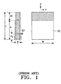
- FIG. 1 is a diagram showing the construction of a prior art quarter-wavelength microstrip antenna (hereinafter, referred to as QMSA) which is described in the above U.S. Patent No. 4,700,194.
- QMSA quarter-wavelength microstrip antenna
- the antenna centering around a dielectric 61, the antenna includes a radiation element on one surface of the dielectric and a ground element on another surface.
- a first feed radiation element 62 (first feeding means) is electrically connected to a signal line of the transmission line.
- a second feed radiation element is constructed on the ground element so as to electrically connect the ground line of the transmission line and the ground element, which is located at a position where the voltage of the standing voltage wave induced on the ground element becomes minimum.
- the ground plane no longer acts as the ground if the size of the ground plane is small relative to the wavelength of the operating frequency.
- a sinusoidal variation of a voltage distribution, or a voltage standing wave is induced on the ground plane.
- a parasitic current is induced on the outer conductor of the coaxial transmission line.
- the outer conductor of the transmission line is connected to the ground element at a second feed point where the voltage of the standing voltage wave induced on the ground element becomes minimum.
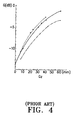
- FIGS. 2 and 4 are diagrams showing variation of the gain characteristic depending upon lengths L, Gz of a quarter-wavelength microstrip antenna according embodiments of the prior art
- FIG. 3 is a diagram showing variation of the gain characteristic depending upon width W of a quarter-wavelength microstrip antenna according an embodiment of the prior art.
- PCB printed circuit board
- EP 0 509 339 A1 relates to an antenna with a top-loading capacity.
- the antenna has an elongation coil and, for matching, an auto transformer.
- the top-loading capacity is formed by a metalized film which is bent approximately in a U-shape in order to increase the capacity.
- the complete circuit, consisting of the top-loading capacity, the elongation coil and auto transformer are configured on a film as a printed circuit.
- the antenna counterweight is configured as a wave trap, especially as a part of the housing of the transmitting/receiving apparatus.
- EP 0 508 567 A2 describes an antenna system for a portable electronic apparatus, particularly for a handset of a cordless telephone system.
- the antenna system comprises two antennas, a first mounted on a flap and comprising a groundplane and an active monopole fed by a coaxial feed from electronic circuitry in a main section of the handset.
- the flap is pivotally connected to the main section of the housing and is folded down against the main section when not in use.
- Another similar antenna is fitted in the main section, and both antennas are connected to the transceiver circuitry via the same node.
- the two antennas are specially designed so as to introduce deliberate mismatch so as to provide an effective switching system between the two antennas without the need for separate circuit elements.
- US 4,644,366 describes a compact, lightweight, printed circuit card antenna which is adaptable to a wide range of frequencies, including very low frequencies.
- the antenna includes a three-dimensional inductor formed on the card, a peripheral conductor stripe on one side of the card which provides a distributed capacitance to the end of the antenna, a peripheral conductor on the opposite side of the card which provides a capacitance to ground, and a transmission line feed point which provides an impedance match to the associated printed circuit flat cable transmission line without the use of impedance matching circuits.
- a small antenna for a portable radio device includes a loaded monopole radiator and a ground radiator.
- the loaded monopole radiator includes first and second conductors on a printed circuit board, where the first conductor has a given length oriented in a horizontal direction, and the second conductor has a meander line shape and is oriented in a vertical direction.
- the ground radiator includes separately a first ground and a second ground at a lower portion of the printed circuit board, where the first and second grounds are symmetrical with respect to the second conductor.
- FIG. 5 is a diagram showing the construction of a monopole antenna according to an embodiment of the present invention.
- the antenna is illustrated for use in conjunction with a two-way pager 10; however, it is understood that the invention has other applications.
- an antenna system 20 is comprised of a conductor radiator 12 of a loaded monopole shape, a ground radiator 13 embodied with a meander line shape, and a coaxial transmission line 27 for connecting the conductor radiator 12 and the ground radiator 13 to a PCB 11 installed with a radio frequency power amplifier.
- the conductor radiator 12 and the ground radiator 13 are deposited at one major surface of the PCB 21, which can be installed in an antenna case 28 of the flip shape.
- the flip antenna case 28 moves, along with the antenna system 20, with respect to the housing of pager 10. That is, antenna system 20 moves between the Y and Z axis, where the pager housing is centered about the X axis. in operation, antenna system 20 is in a vertical position (oriented in the Z direction as shown in FIG. 5).
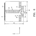
- FIG. 6 is a detailed circuit diagram of the antenna of FIG. 5, showing specifically the PCB 21 of the antenna system 20 in detail.
- the conductor radiator 12 of the loaded monopole shape is composed of a horizonal conductor 23 and a vertical conductor 22, where the conductor 22 has the meander line shape.
- An upper end of the vertical conductor 22 is loaded by the horizontal conductor 23.
- An exemplary electrical length of vertical conductor 22 is 0.49 wavelength and that of the horizontal conductor 23 is 0.3 wavelength.
- This design is based in consideration of the fact that the length of the antenna having the highest gain among equivalent vertical monopole antennas is 0.625 wavelength.
- the overall antenna system 20, which uses a loading unit and a meander line shape and the above lengths to maximize the gain is particularly suitable for use with the rectangular or square flip shape case 28.
- the ground radiator 13 is positioned in the lower portion of the PCB 21 of the antenna system 20 parallel to the horizontal conductor 23. In the configuration shown, the ground radiator 13 is placed in a reflective position on the vertical conductor 22 and is divided into first and second radiators 24 and 25 connected to a ground of the coaxial transmission line 27 at a ground position 26 of the feed point. To enhance the efficiency of the ground radiator 13, each of the first and second ground radiators 24 and 25 preferably has an electrical length of a quarter wavelength.
- the quality of the PCB 21 of the antenna system 20 for use in a preferred embodiment of the present invention may be FR-4, and the thickness thereof is, e.g., 0.25mm.
- the PCB 21 thereof can be inserted into the flip-shape antenna case 28, composed of polycarbonate.
- a capacitor 34 and an inductor 35 are used for impedance matching.
- the antenna efficiency is determined by the radiation efficiency and further, the radiation efficiency can be determined using the following expression 1.
- ⁇ Rr Rr +RL wherein, ⁇ is the radiation efficiency, Rr is a radiation resistance ( ⁇ ), and RL is a loss resistance ( ⁇ ).
- embodiments of the present invention can be designed by employing a meander line shape for the conductor to reduce the physical length of the antenna radiator, while increasing the radiation efficiency by increasing the length of the radiator as a function of the wavelength. Finally, the gain of the antenna can be increased without increasing the physical length of the radiator.
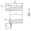
- the horizontal radiator 23 loaded on the radiator 22 is used in the embodiment of the present invention, so that the electric equivalent length can increase by the value required without excessively narrowing the antenna bandwidth. Accordingly, the resulting effect is that the antenna operates in a similar manner as an antenna with a radiator of increased length, thereby enhancing the antenna gain.
- the vertical conductor of the antenna can increase by as much as ⁇ l .
- the input reactive impedances XA and XB of the loaded radiator at positions A and B are as expressed in the following expressions 3 and 4.
- XA -j ZOH 2 Cot ( 2 ⁇ ⁇ lH) wherein, 1H is the length of the "arm" of the horizontal conductor of the loaded monopole (i.e., about half the total horizontal length of the overall horizontal conductor 23) and ZOH is the intrinsic impedance of the horizontal conductor of the loaded monopole.
- XB -j ZOV Cot ( 2 ⁇ ⁇ ⁇ lv) wherein ZOV is intrinsic impedance of the vertical conductor of the loaded monopole.
- the physical length of the monopole antenna is extended as much as ⁇ l v to be operated.
- the terminal case coated with the metal film or the ground of the installed PCB can serve as the ground of the general monopole antenna.
- the radiation efficiency can be still reduced even though the ground thereof serves as the ground radiator. See, "Mobile Antenna Systems Handbook" by K. Fujimoto and J. R. James, Artech House, Boston-London, 1994, P217-243.
- the first and second ground radiators 24 and 25 are adapted in the preferred embodiment of the present invention to minimizing the effect of the human body on the radiation of the monopole antenna when the terminal is placed near the human body. Since the antenna current is separated from the ground of the two-way pager 10, the reduction of the radiation efficiency can be minimized when the device is placed in a user's hand. Also, when the user actually utilizes the terminal, the first and second ground radiators 24 and 25 are included on the PCB 21 of the antenna installed at an upper surface of the two-way pager 10 to be furthest away from the human body during use.
- Radiation from the first and second ground radiators 24 and 25 depends on signal voltage law.
- a varied signal voltage can generate parasitic current flowing along the surface (ground) of the coaxial transmission line 27, thereby easily changing the antenna characteristic such as the directional pattern of the antenna, the input impedance thereof, and the gain thereof.
- the electrical length of the first and second ground radiators 24 and 25 are equal to each other, the parasitic current flowing from the surface of the ground radiator 26 to the ground thereof can be minimized. Consequently, there will be little degradation of the antenna characteristic variation and of the radiation efficiency due to human body contact even if the ground of the two-way pager 10 is positioned adjacent to the human body.
- FIG. 8 shows a graph of gain versus length of a dipole antenna, which can be compared with FIGS. 2-4.
- the gain as shown in each figure is approximately -12.5dBd (-10.35dBi).
- the antenna used in the present embodiment has an electrical length of 0.625 ⁇ .
- the gain of the present embodiment is about 3dBd (5.15dBi) with reference to FIG. 8.
- the prior art has a problem in that the gain can be degraded as much as about 15 dB.
- the graphs of FIGS. 8 and 9 are for a dipole antenna.
- the gain of a monopole antenna is essentially the same as that of an equivalent dipole antenna.
- FIGS. 8 and 9 also represent gain of a monopole antenna according to the present invention).
- the antenna efficiency characteristic ⁇ of the QMSA differs as a function of the thickness d of the PCB.
- the gain according to the variation of the thickness d thereof with reference to FIG. 9 is as below.
- the gain of the aforesaid antenna specification has characteristic of about -12.5dBd.
- the thickness d is 1.2mm and then, as shown in FIG. 9, the antenna efficiency is determined by following factors of expression 9.
- the gain is reduced by about 10dB in comparison with the case of d equaling 1.2mm.
- the gain is reduced by about 25dB in comparison with the gain of the dipole antenna.
- the antenna system according to the present invention can be embodied with a thin PCB, it is lightweight, highly portable and convenient to use, since it is simply installed at the upper surface of the terminal (e.g., paging device). Further, because the vertical radiator placed on the PCB is designed with a meander line shape, the physical length is advantageously reduced to obtain the best electrical characteristic for the limited size of the antenna. Furthermore, since the upper end of the vertical radiator uses another horizontal radiator and the vertical radiator is equivalently increased, it results in an enhanced gain for the antenna. Moreover, since the vertical and horizontal radiators and the ground radiator are embodied with one thin PCB, the antenna is easy to manufacture. Also, the ground radiator prevents the antenna current from flowing on the terminal ground. The variation of the antenna characteristics can be minimized depending upon the variation of the state of the terminal ground, for example, due to body contact. Therefore, the present invention is advantageous in that the antenna can be designed with stable and superior characteristics.
Landscapes
- Support Of Aerials (AREA)
- Details Of Aerials (AREA)
- Input Circuits Of Receivers And Coupling Of Receivers And Audio Equipment (AREA)
- Waveguide Aerials (AREA)
Claims (16)
- Antenne comprenant :une carte (21) à circuits imprimés,un radiateur (12) unipolaire chargé incluant des premier et deuxième conducteurs sur ladite carte (21) à circuits imprimés, ledit premier conducteur (23) ayant une longueur donnée orientée dans une première direction, ledit deuxième conducteur (22) ayant une forme de ligne en méandres et étant orientée dans une deuxième direction perpendiculaire à ladite première direction ; etun radiateur (13) de masse ménagé sur ladite carte (21) à circuits imprimés,ledit radiateur (13) de masse incluant une première masse (24) disposée sur un premier côté dudit deuxième conducteur (22), et une deuxième masse (25) disposée sur un deuxième côté dudit deuxième conducteur (22), lesdites première et deuxième masses ayant chacune une forme de ligne en méandres.
- Antenne selon la revendication 1, dans laquelle ladite première masse (24) et ladite deuxième masse (25) sont incluses de façon séparée dans le ledit radiateur (13) de masse.
- Antenne selon la revendication 1 ou 2, dans laquelle ladite première masse (24) et ladite deuxième masse (25) sont situées à une partie d'extrémité de ladite carte (21) à circuits imprimés.
- Antenne selon l'une des revendications 1 à 3, dans laquelle ledit radiateur (12) unipolaire chargé inclut un conducteur en forme de ligne en méandres orienté dans ladite deuxième direction ainsi qu'une ligne de charge faite d'un conducteur orienté dans ladite première direction se prolongeant à droite et à gauche à une extrémité supérieure dudit conducteur orienté dans ladite deuxième direction.
- Antenne selon l'une des revendications 1 à 4, dans laquelle ledit radiateur (13) de masse a une forme de ligne en méandres, ledit radiateur de masse est orienté de façon symétrique audit deuxième conducteur, et une partie de droite d'un radiateur (24) de masse de gauche et une partie de gauche d'un radiateur (25) de masse de droite sont reliées l'une à l'autre, grâce à quoi chaque longueur électrique desdits radiateurs de masse de droite et de gauche est un multiple impair d'un quart de longueur d'onde.
- Antenne selon l'une des revendications 1 à 5 et étant une petite antenne pour un dispositif radio portable.
- Antenne selon la revendication 1, comportant de plus une ligne (27) de transmission coaxiale destinée à relier le radiateur (12) unipolaire chargé et le radiateur (13) de masse de la carte (21) à circuits imprimés à une autre carte (11) à circuits imprimés installée avec un amplificateur de puissance radiofréquence.
- Antenne selon la revendication 7, dans laquelle ladite ligne (27) de transmission coaxiale a une ligne de signal reliée à une extrémité à une partie inférieure dudit deuxième conducteur (22) dudit radiateur (12) unipolaire chargé et une ligne de masse correspondante reliée auxdits radiateurs de masse de droite et de gauche, une ligne de signal reliée à une autre extrémité à une ligne de signal d'une borne et une ligne de masse correspondante reliée à une partie de masse de ladite borne, grâce à quoi ladite antenne et ladite borne peuvent être reliées électriquement de façon réciproque l'une à l'autre.
- Antenne selon la revendication 1, dans laquelle ladite carte (21) à circuits imprimés est installée dans un boítier d'antenne pliant.
- Antenne selon la revendication 9, dans laquelle ledit boítier d'antenne est composé de polycarbonate.
- Antenne selon la revendication 1, dans laquelle ladite première masse (24) et ladite deuxième masse (25) sont une première partie rayonnante et une deuxième partie rayonnante, respectivement.
- Antenne selon la revendication 11, dans laquelle lesdites première et deuxième parties rayonnantes sont reliées l'une à l'autre.
- Antenne selon la revendication 11 ou 12, dans laquelle lesdites première et deuxième parties rayonnantes sont orientées dans ladite première direction.
- Antenne selon l'une des revendications 11 à 13, dans laquelle au moins l'une desdites première et deuxième parties rayonnantes sont couplées de façon capacitive audit deuxième conducteur.
- Antenne selon l'une des revendications 11 à 13, dans laquelle seule l'une desdites première et deuxième parties rayonnantes est couplée de façon capacitive audit deuxième conducteur.
- Antenne selon l'une des revendications 1 à 15, dans laquelle des dimensions de ladite antenne sont sélectionnées pour permettre à ladite antenne d'être utilisée conjointement avec un dispositif radio portable tenu à la main.
Applications Claiming Priority (4)
| Application Number | Priority Date | Filing Date | Title |
|---|---|---|---|
| KR9652132 | 1996-11-05 | ||
| KR1019960052132A KR100193851B1 (ko) | 1996-11-05 | 1996-11-05 | 휴대용 무선기기의 소형 안테나 |
| KR1900965 | 1996-11-05 | ||
| PCT/KR1997/000166 WO1998020578A1 (fr) | 1996-11-05 | 1997-09-08 | Structure de passage pour cuve de reacteur nucleaire |
Publications (2)
| Publication Number | Publication Date |
|---|---|
| EP0937313A1 EP0937313A1 (fr) | 1999-08-25 |
| EP0937313B1 true EP0937313B1 (fr) | 2005-04-06 |
Family
ID=19480842
Family Applications (1)
| Application Number | Title | Priority Date | Filing Date |
|---|---|---|---|
| EP97939247A Expired - Lifetime EP0937313B1 (fr) | 1996-11-05 | 1997-09-08 | Petite antenne pour dispositif de radio portable |
Country Status (11)
| Country | Link |
|---|---|
| US (1) | US5936587A (fr) |
| EP (1) | EP0937313B1 (fr) |
| JP (1) | JP2000508498A (fr) |
| KR (1) | KR100193851B1 (fr) |
| CN (1) | CN1108643C (fr) |
| AU (1) | AU716524B2 (fr) |
| BR (1) | BR9712738A (fr) |
| DE (1) | DE69732975T2 (fr) |
| IL (1) | IL121693A (fr) |
| RU (1) | RU2178604C2 (fr) |
| WO (1) | WO1998020578A1 (fr) |
Families Citing this family (94)
| Publication number | Priority date | Publication date | Assignee | Title |
|---|---|---|---|---|
| US7019695B2 (en) * | 1997-11-07 | 2006-03-28 | Nathan Cohen | Fractal antenna ground counterpoise, ground planes, and loading elements and microstrip patch antennas with fractal structure |
| GB2323476B (en) * | 1997-03-20 | 2002-01-16 | David Ganeshmoorthy | Communication antenna and equipment |
| KR19990034478A (ko) * | 1997-10-29 | 1999-05-15 | 구자홍 | 이동통신 단말기용 수신장치 |
| SE511068C2 (sv) * | 1997-11-06 | 1999-08-02 | Ericsson Telefon Ab L M | Portabel elektronisk kommunikationsanordning med dubbelbandigt antennsystem |
| SE511131C2 (sv) * | 1997-11-06 | 1999-08-09 | Ericsson Telefon Ab L M | Portabel elektronisk kommunikationsanordning med flerbandigt antennsystem |
| US6107967A (en) * | 1998-07-28 | 2000-08-22 | Wireless Access, Inc. | Billboard antenna |
| US6147653A (en) * | 1998-12-07 | 2000-11-14 | Wallace; Raymond C. | Balanced dipole antenna for mobile phones |
| GB2344969B (en) * | 1998-12-19 | 2003-02-26 | Nec Technologies | Mobile phone with incorporated antenna |
| US6301489B1 (en) | 1998-12-21 | 2001-10-09 | Ericsson Inc. | Flat blade antenna and flip engagement and hinge configurations |
| US6232924B1 (en) | 1998-12-21 | 2001-05-15 | Ericsson Inc. | Flat blade antenna and flip mounting structures |
| US6249688B1 (en) | 1998-12-21 | 2001-06-19 | Ericcson Inc. | Antenna electrical coupling configurations |
| USD431558S (en) * | 1999-03-01 | 2000-10-03 | Ericsson Inc. | Flip and blade antenna for radiotelephone |
| WO2000052784A1 (fr) * | 1999-03-01 | 2000-09-08 | Siemens Aktiengesellschaft | Antenne multibande integrable |
| US6977808B2 (en) * | 1999-05-14 | 2005-12-20 | Apple Computer, Inc. | Display housing for computing device |
| US6357887B1 (en) | 1999-05-14 | 2002-03-19 | Apple Computers, Inc. | Housing for a computing device |
| US6198442B1 (en) * | 1999-07-22 | 2001-03-06 | Ericsson Inc. | Multiple frequency band branch antennas for wireless communicators |
| CN1378712A (zh) * | 1999-08-18 | 2002-11-06 | 艾利森公司 | 一种双频段蝴蝶结/曲折天线 |
| AU5984099A (en) | 1999-09-20 | 2001-04-24 | Fractus, S.A. | Multilevel antennae |
| WO2001047059A1 (fr) * | 1999-12-23 | 2001-06-28 | Rangestar Wireless, Inc. | Antenne a fente a double polarisation |
| WO2001054225A1 (fr) | 2000-01-19 | 2001-07-26 | Fractus, S.A. | Antennes miniatures de remplissage de l'espace |
| JP3640595B2 (ja) * | 2000-05-18 | 2005-04-20 | シャープ株式会社 | 積層パターンアンテナ及びそれを備えた無線通信装置 |
| US6323814B1 (en) * | 2000-05-24 | 2001-11-27 | Bae Systems Information And Electronic Systems Integration Inc | Wideband meander line loaded antenna |
| US6690331B2 (en) | 2000-05-24 | 2004-02-10 | Bae Systems Information And Electronic Systems Integration Inc | Beamforming quad meanderline loaded antenna |
| US6480158B2 (en) | 2000-05-31 | 2002-11-12 | Bae Systems Information And Electronic Systems Integration Inc. | Narrow-band, crossed-element, offset-tuned dual band, dual mode meander line loaded antenna |
| AU2001275024A1 (en) | 2000-05-31 | 2001-12-11 | Bae Systems Information And Electronic Systems Integration, Inc. | Scanning, circularly polarized varied impedance transmission line antenna |
| US6344825B1 (en) * | 2000-08-31 | 2002-02-05 | Inventec Corporation | Antenna apparatus for portable electronic device |
| TW513829B (en) * | 2000-10-12 | 2002-12-11 | Furukawa Electric Co Ltd | Small antenna |
| US6404391B1 (en) * | 2001-01-25 | 2002-06-11 | Bae Systems Information And Electronic System Integration Inc | Meander line loaded tunable patch antenna |
| US7023909B1 (en) | 2001-02-21 | 2006-04-04 | Novatel Wireless, Inc. | Systems and methods for a wireless modem assembly |
| US6842148B2 (en) * | 2001-04-16 | 2005-01-11 | Skycross, Inc. | Fabrication method and apparatus for antenna structures in wireless communications devices |
| DE60215391T2 (de) * | 2001-06-15 | 2007-10-25 | Apple Computer, Inc., Cupertino | Aktives computergehäuse |
| US7766517B2 (en) | 2001-06-15 | 2010-08-03 | Apple Inc. | Active enclosure for computing device |
| US7452098B2 (en) * | 2001-06-15 | 2008-11-18 | Apple Inc. | Active enclosure for computing device |
| US7071889B2 (en) | 2001-08-06 | 2006-07-04 | Actiontec Electronics, Inc. | Low frequency enhanced frequency selective surface technology and applications |
| US9755314B2 (en) | 2001-10-16 | 2017-09-05 | Fractus S.A. | Loaded antenna |
| US6567056B1 (en) * | 2001-11-13 | 2003-05-20 | Intel Corporation | High isolation low loss printed balun feed for a cross dipole structure |
| WO2003063292A1 (fr) * | 2002-01-23 | 2003-07-31 | E-Tenna Corporation | Antenne a plaque court-circuitee inductive a cc |
| US6882316B2 (en) | 2002-01-23 | 2005-04-19 | Actiontec Electronics, Inc. | DC inductive shorted patch antenna |
| WO2003103361A1 (fr) * | 2002-06-03 | 2003-12-11 | Mendolia, Greg, S. | Ecran emi combine et antenne interne pour produits mobiles |
| US7184800B2 (en) * | 2002-10-15 | 2007-02-27 | Kyocera Wireless Corp. | Printed stubby unbalanced dipole antenna |
| BR0315570A (pt) | 2002-10-22 | 2005-08-23 | Jason A Sullivan | Módulo de controle de processamento não-periféricos possuindo propriedades aperfeiçoadas de dissipação de calor |
| CA2504222C (fr) | 2002-10-22 | 2012-05-22 | Jason A. Sullivan | Ordinateur robuste et personnalisable |
| EP1557076A4 (fr) | 2002-10-22 | 2010-01-13 | Jason Sullivan | Systemes et procedes d'elaboration d'une unite de traitement dynamiquement modulaire |
| US7423592B2 (en) | 2004-01-30 | 2008-09-09 | Fractus, S.A. | Multi-band monopole antennas for mobile communications devices |
| JP2006510321A (ja) | 2002-12-22 | 2006-03-23 | フラクタス・ソシエダッド・アノニマ | 移動通信デバイス用のマルチバンド・モノポール・アンテナ |
| JP3833609B2 (ja) * | 2002-12-27 | 2006-10-18 | 本田技研工業株式会社 | 車載アンテナ |
| FI115173B (fi) * | 2002-12-31 | 2005-03-15 | Filtronic Lk Oy | Taitettavan radiolaitteen antenni |
| FR2850966B1 (fr) | 2003-02-10 | 2005-03-18 | Rhodia Polyamide Intermediates | Procede de fabrication de composes dinitriles |
| DE10311040A1 (de) * | 2003-03-13 | 2004-10-07 | Kathrein-Werke Kg | Antennenanordnung |
| FR2854891B1 (fr) | 2003-05-12 | 2006-07-07 | Rhodia Polyamide Intermediates | Procede de preparation de dinitriles |
| US7336243B2 (en) * | 2003-05-29 | 2008-02-26 | Sky Cross, Inc. | Radio frequency identification tag |
| KR100450878B1 (ko) * | 2003-06-13 | 2004-10-13 | 주식회사 에이스테크놀로지 | 중앙 급전 구조를 갖는 이동통신 단말기 내장형 안테나 |
| JP4590595B2 (ja) * | 2003-09-09 | 2010-12-01 | 独立行政法人情報通信研究機構 | 広帯域複数周波共用アンテナ |
| US7193565B2 (en) * | 2004-06-05 | 2007-03-20 | Skycross, Inc. | Meanderline coupled quadband antenna for wireless handsets |
| DE102005030384B3 (de) * | 2005-06-29 | 2006-11-02 | Siemens Ag | Antennevorrichtung für Funk basierte Telefone |
| US7408512B1 (en) * | 2005-10-05 | 2008-08-05 | Sandie Corporation | Antenna with distributed strip and integrated electronic components |
| UA84868C2 (ru) * | 2005-10-11 | 2008-12-10 | Александр Иванович КАРПОВ | Антенна для мобильного радиотелефона |
| US7973174B2 (en) | 2005-10-18 | 2011-07-05 | Invista North America S.A.R.L. | Process of making 3-aminopentanenitrile |
| US20070164909A1 (en) * | 2006-01-13 | 2007-07-19 | Ogawa Harry K | Embedded antenna of a mobile device |
| WO2007109005A2 (fr) | 2006-03-17 | 2007-09-27 | Invista Technologies S.A R.L. | Procédé pour purifier des triorganophosphites grâce au traitement à l'aide d'un adjuvant basique |
| US20070257842A1 (en) * | 2006-05-02 | 2007-11-08 | Air2U Inc. | Coupled-fed antenna device |
| GB2439110B (en) * | 2006-06-13 | 2009-08-19 | Thales Holdings Uk Plc | An ultra wideband antenna |
| US7919646B2 (en) | 2006-07-14 | 2011-04-05 | Invista North America S.A R.L. | Hydrocyanation of 2-pentenenitrile |
| US8738103B2 (en) * | 2006-07-18 | 2014-05-27 | Fractus, S.A. | Multiple-body-configuration multimedia and smartphone multifunction wireless devices |
| US20080143606A1 (en) * | 2006-12-18 | 2008-06-19 | Motorola, Inc. | Antenna assembly and communications assembly |
| CN101687658B (zh) | 2007-05-14 | 2013-07-24 | 因温斯特技术公司 | 高效反应器和方法 |
| WO2008157218A1 (fr) | 2007-06-13 | 2008-12-24 | Invista Technologies S.A.R.L. | Procédé pour améliorer la qualité de l'adiponitrile |
| TW200924281A (en) * | 2007-11-22 | 2009-06-01 | Quanta Comp Inc | Built-in antenna |
| WO2009091790A1 (fr) | 2008-01-15 | 2009-07-23 | Invista Technologies S.A.R.L. | Hydrocyanation de pentènenitriles |
| US7977502B2 (en) | 2008-01-15 | 2011-07-12 | Invista North America S.A R.L. | Process for making and refining 3-pentenenitrile, and for refining 2-methyl-3-butenenitrile |
| EP2334624B1 (fr) | 2008-10-14 | 2014-10-01 | Invista Technologies S.à.r.l. | Procédé de fabrication de 2-alkyl secondaire-4,5-di-(alkyl normal)phénols |
| CN102471218B (zh) | 2009-08-07 | 2014-11-05 | 因温斯特技术公司 | 用于形成二酯的氢化并酯化 |
| USD612838S1 (en) * | 2009-09-08 | 2010-03-30 | Tracker Inc. | Antenna structure for radio tracking receiver |
| WO2012109393A1 (fr) | 2011-02-08 | 2012-08-16 | Henry Cooper | Antenne en cornet à pas en fréquence à gain élevé |
| US9478868B2 (en) | 2011-02-09 | 2016-10-25 | Xi3 | Corrugated horn antenna with enhanced frequency range |
| AU2012333556A1 (en) | 2011-11-01 | 2014-05-15 | Nec Corporation | Artificial satellite with integrated antenna |
| KR101297332B1 (ko) * | 2012-02-28 | 2013-08-14 | 에이트론(주) | 다중 공진 안테나 |
| CN103296422A (zh) * | 2012-03-01 | 2013-09-11 | 华硕电脑股份有限公司 | 电子装置 |
| US20160181690A1 (en) * | 2012-09-19 | 2016-06-23 | Wireless Research Development | Pentaband antenna |
| USD682813S1 (en) * | 2012-12-07 | 2013-05-21 | Cheng Uei Precision Industry Co., Ltd. | Multi-band antenna |
| USD684954S1 (en) * | 2012-12-07 | 2013-06-25 | Cheng Uei Precision Industry Co., Ltd. | Multi-band antenna |
| US9413069B2 (en) * | 2013-02-25 | 2016-08-09 | Taoglas Group Holdings Limited | Compact, multi-port, Wi-Fi dual band MIMO antenna system |
| US9450309B2 (en) | 2013-05-30 | 2016-09-20 | Xi3 | Lobe antenna |
| EP3097605B1 (fr) * | 2014-01-24 | 2018-11-14 | The Antenna Company International N.V. | Module d'antenne, antenne, et dispositif mobile comprenant un tel module d'antenne |
| USD760205S1 (en) * | 2014-03-28 | 2016-06-28 | Lorom Industrial Co., Ltd. | Antenna for glass |
| RU2637365C2 (ru) * | 2015-06-30 | 2017-12-04 | Общество с ограниченной ответственностью "Научно-производственное предприятие "Технологии и системы радиомониторинга" | Малогабаритная широкодиапазонная антенна |
| USD815621S1 (en) | 2016-07-11 | 2018-04-17 | Taoglas Group Holdings Limited | Antenna |
| US10840589B2 (en) | 2016-09-02 | 2020-11-17 | Taoglas Group Holdings Limited | Multi-band MIMO panel antennas |
| GB2556156B (en) | 2016-09-02 | 2022-03-30 | Taoglas Group Holdings Ltd | Multi-band MIMO panel antennas |
| CN110323553B (zh) * | 2019-04-01 | 2021-07-16 | 深圳三星通信技术研究有限公司 | 天线的辐射单元及天线 |
| CN110828990B (zh) * | 2019-10-31 | 2025-01-21 | 深圳市道通智能航空技术股份有限公司 | 一种天线 |
| TWI738343B (zh) * | 2020-05-18 | 2021-09-01 | 為昇科科技股份有限公司 | 蜿蜒天線結構 |
| CN113594697B (zh) | 2021-06-25 | 2022-06-24 | 荣耀终端有限公司 | 一种低sar天线及电子设备 |
| WO2023159345A1 (fr) * | 2022-02-22 | 2023-08-31 | 京东方科技集团股份有限公司 | Antenne |
Citations (3)
| Publication number | Priority date | Publication date | Assignee | Title |
|---|---|---|---|---|
| US4644366A (en) * | 1984-09-26 | 1987-02-17 | Amitec, Inc. | Miniature radio transceiver antenna |
| EP0508567A2 (fr) * | 1991-02-12 | 1992-10-14 | AT&T WIRELESS COMMUNICATIONS PRODUCTS LTD. | Améliorations relatives aux antennes pour un équipement téléphonique portable |
| EP0509339A1 (fr) * | 1991-04-19 | 1992-10-21 | Hagenuk Gmbh | Antenne avec capacité en sommet pour téléphone mobile |
Family Cites Families (10)
| Publication number | Priority date | Publication date | Assignee | Title |
|---|---|---|---|---|
| US4313121A (en) * | 1980-03-13 | 1982-01-26 | The United States Of America As Represented By The Secretary Of The Army | Compact monopole antenna with structured top load |
| US4684953A (en) * | 1984-01-09 | 1987-08-04 | Mcdonnell Douglas Corporation | Reduced height monopole/crossed slot antenna |
| JPH061848B2 (ja) * | 1984-09-17 | 1994-01-05 | 松下電器産業株式会社 | アンテナ |
| JP2515624B2 (ja) * | 1990-11-01 | 1996-07-10 | 原田工業株式会社 | アンテナ結合回路 |
| JPH0690108A (ja) * | 1992-09-07 | 1994-03-29 | Nippon Telegr & Teleph Corp <Ntt> | 小型アンテナ及びその製造方法 |
| AT398532B (de) * | 1992-09-22 | 1994-12-27 | Linser Franz Dr | Krafttrainingsgerät |
| RU2084058C1 (ru) * | 1993-10-08 | 1997-07-10 | Омский научно-исследовательский институт приборостроения | Портативное устройство для радиосвязи |
| DE4410618A1 (de) * | 1994-03-26 | 1995-09-28 | Reitter & Schefenacker Gmbh | Außenrückblickspiegel für Kraftfahrzeuge |
| WO1996027219A1 (fr) * | 1995-02-27 | 1996-09-06 | The Chinese University Of Hong Kong | Antenne en f-inverse a serpentement |
| US5706016A (en) * | 1996-03-27 | 1998-01-06 | Harrison, Ii; Frank B. | Top loaded antenna |
-
1996
- 1996-11-05 KR KR1019960052132A patent/KR100193851B1/ko not_active Expired - Fee Related
-
1997
- 1997-06-30 US US08/884,812 patent/US5936587A/en not_active Expired - Lifetime
- 1997-09-03 IL IL12169397A patent/IL121693A/xx not_active IP Right Cessation
- 1997-09-08 JP JP10521233A patent/JP2000508498A/ja active Pending
- 1997-09-08 BR BR9712738-8A patent/BR9712738A/pt not_active Application Discontinuation
- 1997-09-08 AU AU41377/97A patent/AU716524B2/en not_active Ceased
- 1997-09-08 RU RU99112172/09A patent/RU2178604C2/ru not_active IP Right Cessation
- 1997-09-08 CN CN97199577A patent/CN1108643C/zh not_active Expired - Fee Related
- 1997-09-08 EP EP97939247A patent/EP0937313B1/fr not_active Expired - Lifetime
- 1997-09-08 DE DE69732975T patent/DE69732975T2/de not_active Expired - Fee Related
- 1997-09-08 WO PCT/KR1997/000166 patent/WO1998020578A1/fr not_active Ceased
Patent Citations (3)
| Publication number | Priority date | Publication date | Assignee | Title |
|---|---|---|---|---|
| US4644366A (en) * | 1984-09-26 | 1987-02-17 | Amitec, Inc. | Miniature radio transceiver antenna |
| EP0508567A2 (fr) * | 1991-02-12 | 1992-10-14 | AT&T WIRELESS COMMUNICATIONS PRODUCTS LTD. | Améliorations relatives aux antennes pour un équipement téléphonique portable |
| EP0509339A1 (fr) * | 1991-04-19 | 1992-10-21 | Hagenuk Gmbh | Antenne avec capacité en sommet pour téléphone mobile |
Also Published As
| Publication number | Publication date |
|---|---|
| CN1237278A (zh) | 1999-12-01 |
| DE69732975T2 (de) | 2005-09-08 |
| AU716524B2 (en) | 2000-02-24 |
| IL121693A (en) | 2000-06-01 |
| WO1998020578A1 (fr) | 1998-05-14 |
| JP2000508498A (ja) | 2000-07-04 |
| IL121693A0 (en) | 1998-02-22 |
| EP0937313A1 (fr) | 1999-08-25 |
| CN1108643C (zh) | 2003-05-14 |
| KR100193851B1 (ko) | 1999-06-15 |
| US5936587A (en) | 1999-08-10 |
| DE69732975D1 (de) | 2005-05-12 |
| BR9712738A (pt) | 1999-10-19 |
| AU4137797A (en) | 1998-05-29 |
| RU2178604C2 (ru) | 2002-01-20 |
| KR19980034169A (ko) | 1998-08-05 |
Similar Documents
| Publication | Publication Date | Title |
|---|---|---|
| EP0937313B1 (fr) | Petite antenne pour dispositif de radio portable | |
| EP1018779B1 (fr) | Antenne plane à double fréquence et appareil de radio utilisant une telle antenne | |
| US6424300B1 (en) | Notch antennas and wireless communicators incorporating same | |
| US6801164B2 (en) | Broad band and multi-band antennas | |
| JP3580654B2 (ja) | 共用アンテナおよびこれを用いた携帯無線機 | |
| US4700194A (en) | Small antenna | |
| US7825861B2 (en) | Radio module | |
| AU734079B2 (en) | Bent-segment helical antenna | |
| CN1318213A (zh) | 电容调谐宽带天线结构 | |
| JP2001515692A (ja) | 電気通信装置用アンテナアセンブリ | |
| JP2000516056A (ja) | メアンダ型アンテナ装置 | |
| Esselle | A low-profile compact microwave antenna with high gain and wide bandwidth | |
| WO1997047054A1 (fr) | Antenne a double resonance pour telephone portatif | |
| WO2003041217A2 (fr) | Antenne multibande formee de spires superposees comprimees | |
| WO1998005090A9 (fr) | Antenne helicoidale a segment coude | |
| US6621455B2 (en) | Multiband antenna | |
| US6646619B2 (en) | Broadband antenna assembly of matching circuitry and ground plane conductive radiating element | |
| US20050237244A1 (en) | Compact RF antenna | |
| CN116264348B (zh) | 天线模组及电子设备 | |
| JP2002530909A (ja) | パッチアンテナ装置 | |
| JPS61205004A (ja) | 携帯無線機 | |
| JP2001251128A (ja) | 多周波アンテナ | |
| JP4069271B2 (ja) | 装身用端末機器のパッチアンテナと、それを使用する装身用端末機器のアンテナ装置 | |
| JP2002319809A (ja) | アンテナ装置 | |
| JPH0983238A (ja) | 多波共用アンテナ装置 |
Legal Events
| Date | Code | Title | Description |
|---|---|---|---|
| PUAI | Public reference made under article 153(3) epc to a published international application that has entered the european phase |
Free format text: ORIGINAL CODE: 0009012 |
|
| 17P | Request for examination filed |
Effective date: 19990505 |
|
| AK | Designated contracting states |
Kind code of ref document: A1 Designated state(s): DE FR GB NL SE |
|
| RIN1 | Information on inventor provided before grant (corrected) |
Inventor name: BAK, SANG, KEUN Inventor name: SAMSUNG ELECTRONICS CO.,LTD./MR HA,DONG,IN Inventor name: GUDILEV, ALEXANDRE, V. |
|
| 17Q | First examination report despatched |
Effective date: 20040210 |
|
| GRAP | Despatch of communication of intention to grant a patent |
Free format text: ORIGINAL CODE: EPIDOSNIGR1 |
|
| GRAS | Grant fee paid |
Free format text: ORIGINAL CODE: EPIDOSNIGR3 |
|
| GRAA | (expected) grant |
Free format text: ORIGINAL CODE: 0009210 |
|
| AK | Designated contracting states |
Kind code of ref document: B1 Designated state(s): DE FR GB NL SE |
|
| REG | Reference to a national code |
Ref country code: GB Ref legal event code: FG4D |
|
| REF | Corresponds to: |
Ref document number: 69732975 Country of ref document: DE Date of ref document: 20050512 Kind code of ref document: P |
|
| REG | Reference to a national code |
Ref country code: SE Ref legal event code: TRGR |
|
| PLBE | No opposition filed within time limit |
Free format text: ORIGINAL CODE: 0009261 |
|
| STAA | Information on the status of an ep patent application or granted ep patent |
Free format text: STATUS: NO OPPOSITION FILED WITHIN TIME LIMIT |
|
| ET | Fr: translation filed | ||
| 26N | No opposition filed |
Effective date: 20060110 |
|
| PGFP | Annual fee paid to national office [announced via postgrant information from national office to epo] |
Ref country code: NL Payment date: 20080903 Year of fee payment: 12 Ref country code: FR Payment date: 20080915 Year of fee payment: 12 |
|
| PGFP | Annual fee paid to national office [announced via postgrant information from national office to epo] |
Ref country code: GB Payment date: 20080910 Year of fee payment: 12 |
|
| PGFP | Annual fee paid to national office [announced via postgrant information from national office to epo] |
Ref country code: DE Payment date: 20080919 Year of fee payment: 12 |
|
| PGFP | Annual fee paid to national office [announced via postgrant information from national office to epo] |
Ref country code: SE Payment date: 20080908 Year of fee payment: 12 |
|
| REG | Reference to a national code |
Ref country code: NL Ref legal event code: V1 Effective date: 20100401 |
|
| EUG | Se: european patent has lapsed | ||
| GBPC | Gb: european patent ceased through non-payment of renewal fee |
Effective date: 20090908 |
|
| REG | Reference to a national code |
Ref country code: FR Ref legal event code: ST Effective date: 20100531 |
|
| PG25 | Lapsed in a contracting state [announced via postgrant information from national office to epo] |
Ref country code: NL Free format text: LAPSE BECAUSE OF NON-PAYMENT OF DUE FEES Effective date: 20100401 Ref country code: FR Free format text: LAPSE BECAUSE OF NON-PAYMENT OF DUE FEES Effective date: 20090930 Ref country code: DE Free format text: LAPSE BECAUSE OF NON-PAYMENT OF DUE FEES Effective date: 20100401 |
|
| PG25 | Lapsed in a contracting state [announced via postgrant information from national office to epo] |
Ref country code: GB Free format text: LAPSE BECAUSE OF NON-PAYMENT OF DUE FEES Effective date: 20090908 |
|
| PG25 | Lapsed in a contracting state [announced via postgrant information from national office to epo] |
Ref country code: SE Free format text: LAPSE BECAUSE OF NON-PAYMENT OF DUE FEES Effective date: 20090909 |