EP0937489A1 - Dispositif de séparation d'un mélange par cristallisation fractionnée - Google Patents
Dispositif de séparation d'un mélange par cristallisation fractionnée Download PDFInfo
- Publication number
- EP0937489A1 EP0937489A1 EP98810149A EP98810149A EP0937489A1 EP 0937489 A1 EP0937489 A1 EP 0937489A1 EP 98810149 A EP98810149 A EP 98810149A EP 98810149 A EP98810149 A EP 98810149A EP 0937489 A1 EP0937489 A1 EP 0937489A1
- Authority
- EP
- European Patent Office
- Prior art keywords
- container
- crystallizer
- heat exchanger
- tubes
- heating
- Prior art date
- Legal status (The legal status is an assumption and is not a legal conclusion. Google has not performed a legal analysis and makes no representation as to the accuracy of the status listed.)
- Withdrawn
Links
- 239000000203 mixture Substances 0.000 title claims description 7
- 238000001640 fractional crystallisation Methods 0.000 title claims description 4
- 239000007788 liquid Substances 0.000 claims abstract description 31
- 239000012452 mother liquor Substances 0.000 claims abstract description 8
- 238000010438 heat treatment Methods 0.000 claims description 38
- 230000003068 static effect Effects 0.000 claims description 9
- 239000000047 product Substances 0.000 claims description 8
- 238000005406 washing Methods 0.000 claims description 8
- 239000000126 substance Substances 0.000 claims description 5
- 239000013067 intermediate product Substances 0.000 claims description 3
- 238000001816 cooling Methods 0.000 claims description 2
- 238000005507 spraying Methods 0.000 claims description 2
- 239000007795 chemical reaction product Substances 0.000 claims 1
- 239000013078 crystal Substances 0.000 abstract description 37
- 238000002425 crystallisation Methods 0.000 abstract description 22
- 230000008025 crystallization Effects 0.000 abstract description 22
- 239000000155 melt Substances 0.000 description 9
- 230000035900 sweating Effects 0.000 description 7
- 238000009826 distribution Methods 0.000 description 6
- 239000007791 liquid phase Substances 0.000 description 6
- 238000002844 melting Methods 0.000 description 5
- 239000012530 fluid Substances 0.000 description 4
- 230000008018 melting Effects 0.000 description 4
- 238000010276 construction Methods 0.000 description 3
- 239000000463 material Substances 0.000 description 3
- 238000005192 partition Methods 0.000 description 3
- 238000004519 manufacturing process Methods 0.000 description 2
- 238000004080 punching Methods 0.000 description 2
- 206010010774 Constipation Diseases 0.000 description 1
- 241000270295 Serpentes Species 0.000 description 1
- 238000005452 bending Methods 0.000 description 1
- 238000004140 cleaning Methods 0.000 description 1
- 230000002349 favourable effect Effects 0.000 description 1
- 230000005484 gravity Effects 0.000 description 1
- 239000002184 metal Substances 0.000 description 1
- 238000012986 modification Methods 0.000 description 1
- 230000004048 modification Effects 0.000 description 1
- 239000012768 molten material Substances 0.000 description 1
- 238000012856 packing Methods 0.000 description 1
- 239000012071 phase Substances 0.000 description 1
- 230000008092 positive effect Effects 0.000 description 1
- 238000000926 separation method Methods 0.000 description 1
- 229910001220 stainless steel Inorganic materials 0.000 description 1
- 239000010935 stainless steel Substances 0.000 description 1
Images



Classifications
-
- B—PERFORMING OPERATIONS; TRANSPORTING
- B01—PHYSICAL OR CHEMICAL PROCESSES OR APPARATUS IN GENERAL
- B01D—SEPARATION
- B01D9/00—Crystallisation
- B01D9/0004—Crystallisation cooling by heat exchange
- B01D9/0013—Crystallisation cooling by heat exchange by indirect heat exchange
-
- B—PERFORMING OPERATIONS; TRANSPORTING
- B01—PHYSICAL OR CHEMICAL PROCESSES OR APPARATUS IN GENERAL
- B01D—SEPARATION
- B01D9/00—Crystallisation
- B01D9/004—Fractional crystallisation; Fractionating or rectifying columns
-
- B—PERFORMING OPERATIONS; TRANSPORTING
- B01—PHYSICAL OR CHEMICAL PROCESSES OR APPARATUS IN GENERAL
- B01D—SEPARATION
- B01D9/00—Crystallisation
- B01D9/0072—Crystallisation in microfluidic devices
Definitions
- the present invention relates to a device for Separation of a mixture of substances by means of static, fractional crystallization, with a container for Picking up the mixture or feed, with vertical, via a heat medium, coolable and heatable heat exchanger surfaces in the container, with at least one inlet for each Commodity and an outlet for fractions obtained from it and at least one inlet and one outlet for the heat medium.
- Static crystallizers were originally used Pipe bundle for cooling the melt and heating the Crystallizate used. Later the pipes were put through vertical and transverse to the pipes passed through to the crystallization and To enlarge heat exchange surfaces.
- Today in the Most common crystallizers for the static industry Crystallization are so-called plate crystallizers, their Heat exchanger elements are double-walled plate elements.
- Plate crystallizers are a number of identical ones Plate elements arranged in a cubic container. Circulated between the two walls of a plate element the heat exchange fluid and between the Plate elements or between them and the container wall feed is poured in and out of it on the plate elements a crystal layer crystallized.
- These plate elements however, are expensive to manufacture and only suitable for cubic containers, since they are cost and Control reasons should preferably be the same.
- a disadvantage of cubic containers is that they are against Differences in pressure are sensitive, are difficult to clean and like to accumulate deposits in corners and edges.
- EP-A 0 051 551 proposes in one cylindrical crystallizer housing parallel to the Arrange cylinder axis tubes in an orthogonal grid and between these heat exchanger tubes plates, which in thermal contact with the pipes.
- This Plates should distribute the heat across the pipes and as Crystallization surfaces serve.
- These plates are upright to them running beams, which also the kink length limit the pipes.
- the plates have different Spread, however, the same height so that a cylindrical section with parallel to the cylinder axis Plates can be fitted between the tubes.
- Several such sections are arranged one above the other, and between the sections with an intermediate floor is a drain for running liquid components provided.
- the object of the invention is therefore a static one To propose crystallizer, which the above mentioned Avoids disadvantages, efficient heat transfer between input material and heat medium and its Heat exchanger elements can be manufactured inexpensively can, the highest possible construction of the crystallizer allow and in particular to propose a crystallizer, which with a similar heat exchanger elements cylindrical container is filled practically homogeneously. Of the Space requirements of the entire crystallization system should also be be minimal.
- the Heat exchanger surfaces through vertically arranged Longitudinal finned tubes are formed.
- Longitudinal finned tubes are in the Commercially available bulk products, which are for heat exchangers can be produced in a variety of variations.
- she have a surface up to twenty times larger than Pipes without fins of the same size.
- the ribs parallel to the tubes are in one vertically aligned tubes equipped crystallizer only vertical surfaces in front of what the drainage behavior of the Melt or mother liquor favorably influenced.
- Advantageous for the drainage behavior is especially when the pipes and the ribs from the bottom of the container to just above that Filling level of the container are continuous. Thereby occur continuously when sweating or melting vertical drainage channels, in which draining liquid phase quickly escapes from the crystallized cake.
- the longitudinal ribs are advantageously welded to the tube, to ensure optimal heat transfer, and the Longitudinal finned tubes made of a material used in chemical plant construction stainless steel.
- Longitudinal finned tubes have a very good load capacity on.
- the kink length of a pipe is determined by attaching Longitudinal ribs significantly extended, so that with a Longitudinal finned tube can carry high loads and therefore high crystallizers can be built, provided that Dead weight of the crystals when sweating on the Heat exchanger can be transferred.
- a preferred one Cross-sectional shape is the round one.
- a round container wall can have pressure differences between the container and the environment absorb better than a level. This is all the more necessary the higher a static crystallizer is formed, because the pressures at least when the crystal cake melts on the lowest part of the wall with the height of the Increase the crystallizer.
- a cylindrical container space has moreover opposite a cubic container space more favorable ratio between surface and volume, which in turn has a positive effect on the energy balance of Operating a crystallizer affects.
- a round shape has no corners that are susceptible to deposits, which also affects the cleaning of the container.
- the finned tubes are advantageous in one Triangular arrangement with a constant side length.
- the Triangular arrangement is the densest packing of rounds Cross sections. This is the whole crystallization space evenly equipped with heat exchanger surfaces, all of which can have the same shape.
- the ribs are advantageously perforated. This will make the Adhesion between the crystals and the heat exchanger surface increased, because the crystals on both sides and beyond a rib the heat exchanger surface is connected through.
- the Crystalline therefore not only lasts through friction and adhesion, but it is hung on the heat exchanger surface and must be sheared off to be able to slide off. Therefore can Crystallizers with longitudinal finned tubes, the fins of which are perforated are used for a larger range of mixtures are called plate crystallizers.
- the ribs advantageously have surfaces which deviate substantially from the vertical or at an angle to face the ribs. For example Brows at the edges of the holes or bent out of the surface Be part of the ribs. These are not vertical Edges and surfaces increase the shear force, which is necessary is to tear the crystals from the ribs.
- the necessary shear force to shear the is advantageous Crystals together with the adhesion between crystals and heat exchanger surface so high during sweating that the crystals are carried. This enables the Build the crystallizer at any height. Such a facility therefore requires less than conventional systems Floor space.
- Admission as a distributor for watering is advantageous or spraying the heat exchanger surfaces and formed over arranged the heat exchanger surfaces. This allows the Heat exchanger surface are poured and a liquid over the goods to be distributed.
- the bottom of the container is advantageously curved toward the top. If the uppermost point of the curvature is approximately centric, it runs running melt or mother liquor against the edge of the Crystallizer. With a round base of the container the drainage paths are ideal. The more fluid arises, the more inclined the floor surface is and the more the area over which the liquid is also larger can expire.
- a permeable grid floor arranged. This is a Drain channel, or a drain layer, defined, and falling pieces of crystals can drain the drain do not clog.
- Heating pipes arranged or the bottom of the container is heated. This allows the drain channel for mother liquor to be drained or melt can be melted free.
- Such a crystallizer advantageously has one heated ring channel for collecting and feeding to the outlet of draining fractions or draining mother liquor on, and advantageously also a ring channel for distribution and Collect one the bottom of the container or the one above Heating the heating tubes arranged in the tank bottom Heating medium.
- the ring-shaped inlet and outlet connects in simplest way a plurality of individual lines or individual outlet openings.
- the ring channels are advantageous formed by two approximately concentric half tubes and outside arranged on the container wall, the annular channel for the liquid components of the feed within the Ring channel is arranged for the heating medium. This can a separate heating of the drain channel can be connected and the running liquid phases can over the Melting temperature to be heated. So it becomes a stiffness the liquid phase is prevented and the running phases liquefied.
- the container wall is advantageously heatable and coolable. As a result, there are no temperature differences between the Center and periphery of the operational goods.
- Such a crystallizer is also advantageous arranged a tank tower, whereby the space requirement regarding Footprint is minimal.
- the tank tower at least exists from a tank, which is designed as a vertical cylinder is, but is preferably with intermediate floors in different Tanks divided.
- the ones to be filled in the tank Liquids are advantageously stored in tanks, which a pump are arranged. This allows you to use this one Pump the various liquids into the crystallizer be pumped.
- a tank tower is in the same day filed Swiss patent application in detail described.
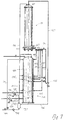
- the crystallizer 11 according to FIG. 1 has a housing 13 on which consists of a housing base 15, a housing wall 17 and a housing cover 19 is composed. Housing bottom 15 and housing cover 19 are over flanges 21 or 23 with the housing wall 17 or its flanges 21 ', 23' detachably screwed.
- the housing 13 is through a upwardly curved container bottom 25 in two chambers divided, namely into an upper crystallization chamber 27, which as a container for a feed from one to separating mixture of substances and a lower medium chamber 29, which serves as a collecting space for the heat medium to be removed serves.
- an upper crystallization chamber 27 which as a container for a feed from one to separating mixture of substances
- a lower medium chamber 29 which serves as a collecting space for the heat medium to be removed serves.
- Heat exchanger 31 In the container for by static crystallization too separating feed, or in the crystallization chamber 27 a plurality of heat exchangers 31 are arranged, from which only one is shown in Figure 1.
- Heat exchanger 31 consists of a tube 39, which on its upper end 33 is closed and with its lower end 35 down through the container bottom 25 into the medium chamber 29 enough.
- the upper end 33 is held by a grid 37, so that the tube 39 does not move laterally, but in the length can expand and contract.
- the interior of the pipe is open to the medium chamber.
- the pipe 39 is continuous with almost its entire length Provided longitudinal ribs 41.
- Inside the tube 39 is one Medium line 43 led up to its upper end 33.
- the Medium lines 43 are with a distribution chamber 45 Housing bottom 15 connected.
- the connection is with Plug connections 47 made, which when removing the Housing bottom 15 of the medium lines 43 inserted therein to be pulled.
- the nozzle 51 is for the liquid to be supplied Heat medium, the nozzle 53 for the liquid and to be discharged gaseous heat medium and the nozzle 55 for the Pressure regulation in the medium chamber 29 and the pipes 39.
- the connector 55 for pressure regulation has a pipe stub 57 on, which stands above the housing base 15 and up close to the container bottom 25 is sufficient because for pressure regulation working with the gaseous heating medium.
- an outlet channel 59 with a sieve tray 61 from the one above Crystallization chamber 27 separated. Between sieve plate 61 and tank bottom 25 are heating pipes 63 in the drain channel 59 arranged.
- the drain channel 59 is with an outside of the Housing wall 17 arranged ring channel 65 for collecting connected by draining liquid.
- the ring channel 65 is can be emptied via an outlet 67.
- a second is concentric around the ring channel 65 Ring channel 69 arranged with which in one half (Figure 2, 71) distributes a heating medium to the heating lines 63 and collected in the other half ( Figures 2, 73) becomes.
- the ring channel 69 is provided with two partitions (FIG 2, 75) divided into two halves.
- a feed line 79 and a return line 77 are arranged for the heating medium.
- the housing cover 19 is curved. Under the Housing cover 19 is a distributor plate or distributor 81 with a plurality of downward openings 83 and one Annular gap between distributor and container wall 17 or Container lid 19 arranged. Via the distributor 81 Crystallization chamber filled with feed. in the An opening 87 is also provided in the housing cover 19 which is the gas exchange when filling or emptying the Crystallizer can take place.
- Figure 2 shows a horizontal section through the Crystallization chamber 27.
- the chamber of longitudinal finned tubes 91 arranged in a 60 degree grid.
- the schematically drawn ribs 41 are even on all sides of the pipes 39.
- the Longitudinal finned tubes 91 the space is vertical in many continuous crystallization zones divided, whose Dimensions in the horizontal directions relative to Are very small.
- the number of ribs can be so large be chosen so that the crystals layer at Sweating has enough grip to keep her weight on the body To remove fins and the longitudinal finned tubes.
- the weight of the Crystals therefore hang on the longitudinal finned tubes 91 and the housing wall 17.
- the housing wall is namely when this is also not shown, also heatable and coolable, and thus serves as a crystallization surface.
- the sieve plate 61 arranged above the heating pipes 63 is not shown in Figure 2.
- the heating pipes 63 overflow the tank bottom 25 in a straight line between the tubes 39 through and end on both sides in a distribution 71 or Collecting channel 73. Together they form an annular channel 69, which is divided into two parts with partitions 75.
- the partitions 75 are perpendicular to the Heating lines 63 aligned line through the center the crystallization chamber 27 is arranged.
- Inlet 79 for the heating medium is on the side of the outlet 67 for the Melts arranged.
- Within the ring channel 69 for that The heating medium is the ring channel 65 for the melting material or the expiring mother liquor arranged.
- Figure 3 shows a cross section through two Longitudinal finned tubes 91.
- the longitudinal finned tube 91 is made of one Tube 39 and an even number of double fins 41 ', 41' ' compiled.
- the double ribs 41 are on the connecting web 93 welded together with the pipe 39.
- the ribs different lengths Every second of the 12 double ribs 41 ', 41' 'is trained longer than the other, so the longer Double ribs 41 '' on the corner points of a regular Hexagons and the shorter double ribs 41 'on the Side faces of the hexagon are aligned.
- This medium line 43 is cut in FIG drawn. It extends below the tube 39 and is with the distribution chamber (Fig. 1, 45) connected.
- the pipe 39 against it is open to the medium chamber (Fig. 1, 29), so that Gaseous and / or liquid heating medium after Heat exchange in the pipe 39 flows into the medium chamber 29.
- the tube 39 is located in the tank bottom 25. Above the tank bottom is between the container bottom 25 and the sieve bottom 61 Intermediate space or drain channel 59 separated.
- Sieve plate 61 is welded onto the heating pipes 63. This will make the Openings 95 in the sieve plate 61 melted as soon as the Heating pipes 63 are heated.
- FIG. 5 shows a detail section through the ring channels 65 and 69 at outlet 67 for liquid components of the Good use.
- the heating lines 63 are connected to the outside Ring channel 69 connected.
- the heating pipes 63 not only heat the Gap or drain channel 59, but also the Ring channel 65 and the feed contained therein, since they are passed through the inner ring channel 65 and the outer ring channel 69 surrounds the inner ring channel 65.
- Of the Outlet 67 for liquid phases is at the bottom of the semi-tubular ring channel 65 arranged and down directed.
- FIG. 6 is a detail section through an alternative Embodiment of the heated ring channel 65 of Figure 5.
- Der Ring channel 65 in Figure 6 is by trace heating pipes 69 ' heated, which are welded onto the ring channel 65.
- Of the Outlet 67 is also in shape with trace heating a 69 '' cuff.
- the heating pipes 63 for the Drain channel 59 above the container bottom 25 are in one Snake line back and forth through the container. she cross again and again the ring channel 65. In this All weld seams are accessible.
- Fig. 7 shows a preferred arrangement of Crystallizer 11 and tank system 101.
- the crystallizer 11 is as little as possible To take up space. This goal also applies to the whole Transferring the crystallization system are the different Tanks, to a vertically piled up unit 101 been summarized.
- the tank tower 101 In the tank tower 101 there is a feed tank 103 at the top, including a washer fluid tank 105, then a Product tank 107 and at the bottom a residue tank 109 arranged.
- This tank tower 101 can also, for example Intermediate product tanks to be expanded. Individual intermediate floors separate the different tanks.
- the crystallizer 11 is above the tank tower 101 arranged so that draining liquids thanks to the Gravity fed into the corresponding tanks without pumps can be.
- Another Line 123 behind another slide connects the Distribution line 111 with a pump 125.
- Outlets in the tanks 103,105 for the starting product and for the washing liquid, and possibly in the tanks for Intermediate products are connected to the line via a slide each 123 connected so these liquids with the pump 125 can be pumped into the crystallizer 11.
- the corresponding tanks 107, 109 each have an outlet and one on top Line 128, 129 provided, which each to a separate pump 131, 133 are connected. Because these liquids no longer need to be pumped into the crystallizer 11, but are forwarded or disposed of.
- the pumps 125, 131, 133 are on drain lines 135 connected, causing them and those connected to them Lines 111, 123, 127, 128, 129 via drain lines 135 can be emptied.
- the drain lines 135 are in one Emptying tank 137 guided, which via a pump 139 either via line 141 into feed tank 103 or via line 143 can be drained out of the system.
- the afterwards drained liquid mother liquor remains in the Residue tank 109 let out.
- a washing liquid stored in the tank 105 which with the Pump 125 pumped up over the crystals and with the Distributor 81 is distributed from residual quantities in the Crystallized remaining liquid components cleaned. Due to the small footprint with a large height of The volume of crystals becomes relatively little washing liquid needed because the washing liquid has a long way to go covers the crystals.
- the washing liquid then runs into the feed tank 103.
- FIGs 8 to 13 are exemplary embodiments of Perforations on the longitudinal ribs 41, 41 'are shown.
- Figures 8 and FIG. 9 are views of the fins 41, the tube 39 and the Connecting web 93 of double ribs is cut, figures 10 to 13 represent vertical cuts through the perforations.
- the perforation can be circular, as shown in Figure 8, with Elongated holes, as shown in Figure 9, or with Holes of various other shapes are carried out.
- the Holes can be shifted vertically (Fig. 8) or be arranged perpendicular to each other (Fig. 9).
- the size of the holes can vary.
- the punched or heat exchanger surface can be lost milled sheet metal piece connected to the rib at one edge stay. This is shown in Figures 10 and 13.
- connection via a side (Fig. 10) or a lower (Fig. 13) or an upper edge remain.
- the bending axis also becomes horizontal, run inclined or vertical (Fig. 10). If for example an elongated hole cutout according to FIG. 9 is bent as in Figure 13, the inclined surfaces both against the rib 41 and against the tube 39 inclined.
- FIG. 12 A very simple embodiment is shown in FIG. 12 shown, in which the perforation is punched out and the Rib 41 is flat on both sides.
- an appropriate Modification of the punching tool can be done with the punching at the same time a brow, as shown in Figure 11 is to be bent up. All of these and similar ones Measures serve to keep the crystal layer on the Increase heat exchanger area so that the crystals when Sweating does not slip.
Landscapes
- Chemical & Material Sciences (AREA)
- Crystallography & Structural Chemistry (AREA)
- Chemical Kinetics & Catalysis (AREA)
- Physics & Mathematics (AREA)
- Thermal Sciences (AREA)
- Heat-Exchange Devices With Radiators And Conduit Assemblies (AREA)
Priority Applications (1)
| Application Number | Priority Date | Filing Date | Title |
|---|---|---|---|
| EP98810149A EP0937489A1 (fr) | 1998-02-24 | 1998-02-24 | Dispositif de séparation d'un mélange par cristallisation fractionnée |
Applications Claiming Priority (1)
| Application Number | Priority Date | Filing Date | Title |
|---|---|---|---|
| EP98810149A EP0937489A1 (fr) | 1998-02-24 | 1998-02-24 | Dispositif de séparation d'un mélange par cristallisation fractionnée |
Publications (1)
| Publication Number | Publication Date |
|---|---|
| EP0937489A1 true EP0937489A1 (fr) | 1999-08-25 |
Family
ID=8235961
Family Applications (1)
| Application Number | Title | Priority Date | Filing Date |
|---|---|---|---|
| EP98810149A Withdrawn EP0937489A1 (fr) | 1998-02-24 | 1998-02-24 | Dispositif de séparation d'un mélange par cristallisation fractionnée |
Country Status (1)
| Country | Link |
|---|---|
| EP (1) | EP0937489A1 (fr) |
Cited By (3)
| Publication number | Priority date | Publication date | Assignee | Title |
|---|---|---|---|---|
| EP1216734A1 (fr) * | 2000-12-22 | 2002-06-26 | Sulzer Chemtech AG | Procédé et dispositif de cristallisation pour la séparation de mélanges à plusieurs composants |
| FR2998806A1 (fr) * | 2012-12-03 | 2014-06-06 | Arkema France | Procede de purification par cristallisation fractionnee en milieu fondu sur surfaces texturees |
| FR3056411A1 (fr) * | 2016-09-27 | 2018-03-30 | Fives Proabd | Procede de purification par cristalisation et installation pour la mise en oeuvre d'un tel procede |
Citations (4)
| Publication number | Priority date | Publication date | Assignee | Title |
|---|---|---|---|---|
| US3272875A (en) * | 1965-04-26 | 1966-09-13 | Du Pont | Surface crystallization process |
| EP0143472A2 (fr) * | 1983-11-25 | 1985-06-05 | Rütgerswerke Aktiengesellschaft | Procédé de traitement du phénol brut provenant de la liquéfaction du charbon |
| EP0715870A1 (fr) * | 1994-12-08 | 1996-06-12 | Sulzer Chemtech AG | Procédé et dispositif de déparation de masse d'un mélange liquide par cristallisation fractionnée |
| EP0811410A1 (fr) * | 1996-06-05 | 1997-12-10 | Sulzer Chemtech AG | Procédé et dispositif de séparation d'un mélange liquide par cristallisation fractionnée |
-
1998
- 1998-02-24 EP EP98810149A patent/EP0937489A1/fr not_active Withdrawn
Patent Citations (4)
| Publication number | Priority date | Publication date | Assignee | Title |
|---|---|---|---|---|
| US3272875A (en) * | 1965-04-26 | 1966-09-13 | Du Pont | Surface crystallization process |
| EP0143472A2 (fr) * | 1983-11-25 | 1985-06-05 | Rütgerswerke Aktiengesellschaft | Procédé de traitement du phénol brut provenant de la liquéfaction du charbon |
| EP0715870A1 (fr) * | 1994-12-08 | 1996-06-12 | Sulzer Chemtech AG | Procédé et dispositif de déparation de masse d'un mélange liquide par cristallisation fractionnée |
| EP0811410A1 (fr) * | 1996-06-05 | 1997-12-10 | Sulzer Chemtech AG | Procédé et dispositif de séparation d'un mélange liquide par cristallisation fractionnée |
Non-Patent Citations (1)
| Title |
|---|
| "Ullmanns Encyklopädie der technischen Chemie", 1972, VERLAG CHEMIE, WEINHEIM/BERGSTR., XP002067960, 2 * |
Cited By (3)
| Publication number | Priority date | Publication date | Assignee | Title |
|---|---|---|---|---|
| EP1216734A1 (fr) * | 2000-12-22 | 2002-06-26 | Sulzer Chemtech AG | Procédé et dispositif de cristallisation pour la séparation de mélanges à plusieurs composants |
| FR2998806A1 (fr) * | 2012-12-03 | 2014-06-06 | Arkema France | Procede de purification par cristallisation fractionnee en milieu fondu sur surfaces texturees |
| FR3056411A1 (fr) * | 2016-09-27 | 2018-03-30 | Fives Proabd | Procede de purification par cristalisation et installation pour la mise en oeuvre d'un tel procede |
Similar Documents
| Publication | Publication Date | Title |
|---|---|---|
| DE60202611T2 (de) | System zum strippen und rektifizieren eines fluidgemisches | |
| DE60127832T2 (de) | Boden für fraktionierte destillation und verfahren | |
| EP0229356B1 (fr) | Dispositif de lavage à contre-courant à plusieurs étages, l'application et les mesures d'opération | |
| DE2602679A1 (de) | Verfahren zur herstellung eines luftgekuehlten, atmosphaerischen waermeaustauschers | |
| DE69117196T2 (de) | VORRICHTUNG ZUM VERDAMPFEN EINER FLüSSIGKEIT UND IHRER NACHFOLGENDEN KONDENSATION | |
| EP2476970B1 (fr) | Réservoir de fluide | |
| DE2165739C3 (de) | Filterkörper | |
| DE2232386C3 (de) | Vorrichtung zur Kältetrocknung von Gas, insbesondere Luft | |
| DE2449383A1 (de) | Gitteranordnung fuer dampf-fluessigkeits-kontaktbehaelter | |
| DE1544027A1 (de) | Gitter fuer Einrichtungen,in denen Daempfe und Fluessigkeiten miteinander in Beruehrung gebracht werden | |
| DE69529146T2 (de) | Destillationskolonne mit innerem wärmeaustausch | |
| DE3144863C2 (de) | Wärmetauscher mit Fließbett | |
| EP0640385A1 (fr) | Garnissage avec des matériaux catalytiques ou adsorbants | |
| WO2011054504A1 (fr) | Grille de garniture ondulée et garniture ordonnée, constituée de plusieurs grilles de garniture | |
| DE60305650T2 (de) | Wärmeintegrierte destillationssäule | |
| DE69903713T2 (de) | Verfahren zum beeinflussen von stoffaustausch zwischen einer flüssigen und einer gasphase | |
| DE2222269A1 (de) | Rektifizierturm oder -kolonne | |
| EP0031153B1 (fr) | Système d'accumulation de chaleur pour le stockage de chaleur solaire ou de chaleur perdue dans plusieurs réservoirs d'accumulation | |
| DE3110859C2 (fr) | ||
| EP0925109B1 (fr) | Chicanes pour colonnes d'echange de substance | |
| DE1275507B (de) | Duennschichtverdampfer | |
| CH663904A5 (de) | Fluessigkeitsverteiler fuer eine stoffaustauschkolonne. | |
| DE69730436T2 (de) | Packung für trennkolonnen und verfahren zu ihrer verwendung | |
| WO2017194203A1 (fr) | Dispositif de collecte de liquide, colonne de transfert de matière et procédé de fabrication d'un tel dispositif de collecte de liquide | |
| EP0657210B1 (fr) | Elément de remplissage pour installations pour l'échange d'énergie et/ou de matière et/ou pour effectuer des réactions chimiques |
Legal Events
| Date | Code | Title | Description |
|---|---|---|---|
| PUAI | Public reference made under article 153(3) epc to a published international application that has entered the european phase |
Free format text: ORIGINAL CODE: 0009012 |
|
| 17P | Request for examination filed |
Effective date: 19980907 |
|
| AK | Designated contracting states |
Kind code of ref document: A1 Designated state(s): AT BE CH DE DK ES FI FR GB GR IE IT LI LU MC NL PT SE |
|
| AX | Request for extension of the european patent |
Free format text: AL;LT;LV;MK;RO;SI |
|
| AKX | Designation fees paid | ||
| REG | Reference to a national code |
Ref country code: DE Ref legal event code: 8566 |
|
| STAA | Information on the status of an ep patent application or granted ep patent |
Free format text: STATUS: THE APPLICATION IS DEEMED TO BE WITHDRAWN |
|
| 18D | Application deemed to be withdrawn |
Effective date: 20000226 |