EP0937523A2 - Procédé de fabrication de dentures intérieures et extérieures - Google Patents
Procédé de fabrication de dentures intérieures et extérieures Download PDFInfo
- Publication number
- EP0937523A2 EP0937523A2 EP99301343A EP99301343A EP0937523A2 EP 0937523 A2 EP0937523 A2 EP 0937523A2 EP 99301343 A EP99301343 A EP 99301343A EP 99301343 A EP99301343 A EP 99301343A EP 0937523 A2 EP0937523 A2 EP 0937523A2
- Authority
- EP
- European Patent Office
- Prior art keywords
- gear
- teeth
- plate material
- surface side
- back surface
- Prior art date
- Legal status (The legal status is an assumption and is not a legal conclusion. Google has not performed a legal analysis and makes no representation as to the accuracy of the status listed.)
- Withdrawn
Links
Images


Classifications
-
- B—PERFORMING OPERATIONS; TRANSPORTING
- B21—MECHANICAL METAL-WORKING WITHOUT ESSENTIALLY REMOVING MATERIAL; PUNCHING METAL
- B21D—WORKING OR PROCESSING OF SHEET METAL OR METAL TUBES, RODS OR PROFILES WITHOUT ESSENTIALLY REMOVING MATERIAL; PUNCHING METAL
- B21D53/00—Making other particular articles
-
- B—PERFORMING OPERATIONS; TRANSPORTING
- B60—VEHICLES IN GENERAL
- B60N—SEATS SPECIALLY ADAPTED FOR VEHICLES; VEHICLE PASSENGER ACCOMMODATION NOT OTHERWISE PROVIDED FOR
- B60N2/00—Seats specially adapted for vehicles; Arrangement or mounting of seats in vehicles
- B60N2/02—Seats specially adapted for vehicles; Arrangement or mounting of seats in vehicles the seat or part thereof being movable, e.g. adjustable
- B60N2/22—Seats specially adapted for vehicles; Arrangement or mounting of seats in vehicles the seat or part thereof being movable, e.g. adjustable the back-rest being adjustable
- B60N2/225—Seats specially adapted for vehicles; Arrangement or mounting of seats in vehicles the seat or part thereof being movable, e.g. adjustable the back-rest being adjustable by cycloidal or planetary mechanisms
- B60N2/2252—Seats specially adapted for vehicles; Arrangement or mounting of seats in vehicles the seat or part thereof being movable, e.g. adjustable the back-rest being adjustable by cycloidal or planetary mechanisms in which the central axis of the gearing lies inside the periphery of an orbital gear, e.g. one gear without sun gear
-
- B—PERFORMING OPERATIONS; TRANSPORTING
- B21—MECHANICAL METAL-WORKING WITHOUT ESSENTIALLY REMOVING MATERIAL; PUNCHING METAL
- B21D—WORKING OR PROCESSING OF SHEET METAL OR METAL TUBES, RODS OR PROFILES WITHOUT ESSENTIALLY REMOVING MATERIAL; PUNCHING METAL
- B21D53/00—Making other particular articles
- B21D53/26—Making other particular articles wheels or the like
- B21D53/28—Making other particular articles wheels or the like gear wheels
-
- B—PERFORMING OPERATIONS; TRANSPORTING
- B21—MECHANICAL METAL-WORKING WITHOUT ESSENTIALLY REMOVING MATERIAL; PUNCHING METAL
- B21K—MAKING FORGED OR PRESSED METAL PRODUCTS, e.g. HORSE-SHOES, RIVETS, BOLTS OR WHEELS
- B21K1/00—Making machine elements
- B21K1/28—Making machine elements wheels; discs
- B21K1/30—Making machine elements wheels; discs with gear-teeth
Definitions
- the present invention relates to outer teeth, inner teeth, and a producing method thereof, and more particularly, to outer teeth, inner teeth, and a producing method thereof used for a reclining mechanism of a seat of a vehicle.
- a Taumel mechanism is used as one example in a reclining mechanism of a vehicle seat.
- a pair of outer teeth and inner teeth are used, and each of the outer and inner teeth are formed by one time precision extrusion.
- each tooth of the inner and outer teeth formed at the time of extrusion is pressed by the press dies along the tooth shape, the opposite side from the pressed side is drawn by remaining portion to generate sags, and the sags of the drawn portion become greater as approaching the tip end of the tooth.
- an outer teeth gear comprising: a plate material having a surface side, a back surface side, and a circular recess which is formed on the back surface side and is defined by an inner peripheral surface; a circular projection which is formed on the surface side of the plate material corresponding to the circular recess on the back surface side by extrusion forming and has an outer peripheral portion; a gear tooth which is formed around the outer peripheral portion of the circular projection by pressing back the outer peripheral portion of the circular projection at an equal distance toward the back surface side of the plate material and has a valley; and a connection portion which projects toward the back surface side of the plate material corresponding to the valley of the gear tooth and is connected to the inner peripheral surface of the circular recess.
- a equal distance means a length between a gear tooth and a neighbor's gear tooth thereof.
- the gear teeth are formed by pressing back the outer peripheral portion of the circular projection which is previously formed by extrusion forming on the surface of the plate material toward the back surface side of the plate material.
- the material which is pressed back and moved toward the back surface side of the plate material is connected to the inner peripheral surface of the circular recess which is formed on the back surface side of the circular projection, and is formed as the connection portion.
- the pressed back material is plastically deformed and formed as the connection portion. Remaining pressed back material flows into a superposed portion of the plate material and the circular projection.
- connection portion formed at the back surface side can be formed of only material which is required for securing the strength, waste of material can be reduced, and since composition (flow) of the material of the superposed portion of the plate material and the circular projection is continuous, its strength can be increased.
- an inner teeth gear comprisiny: a plate material which has a surface side, a back surface side, and a circular recess which is formed on the surface side by intrusion forming and is defined by an inner peripheral portion; a circular projection which is formed on the back surface side of the plate material corresponding to the circular recess and has an outer periphery portion; a gear tooth which is formed around the inner peripheral portion of the circular recess by pressing a surrounding portion surrounding the circular recess at an equal distance toward the back surface side of the plate material and has a valley; and a connection portion which projects toward the back surface side of the plate material corresponding to the valley of the gear tooth and is connected to the outer peripheral surface of the circular projection.
- the gear teeth are formed by pressing the surrounding portion of the circular recess which is previously formed by intrusion forming on the surface of the plate material toward the back surface side of the plate material.
- the material which is pressed and moved toward the back surface side of the plate material is connected to the outer peripheral surface of the circular projection which is formed on the back surface side of the circular recess, and is formed as the connection portion.
- the pressed back material is plastically deformed and formed as the connection portion. Remaining pressed material flows into a superposed portion of the plate material and the circular recess.
- connection portion formed at the back surface side can be formed of only material which is required for securing the strength, waste of material can be reduced, and since composition (flow) of the material of the superposed portion of the plate material and the circular recess is continuous, its strength can be increased.
- a producing method of an outer teeth gear by forming gear teeth around an outer peripheral surface of a circular projection which is formed from a plate material by extrusion forming, and the producing method comprises: a first step for pressing a plate material for extrusion forming, in an embossed manner, a circular projection having a diameter greater than that of a gear tooth to be formed at a surface side of a plate material; and a second step for pressing back an outer peripheral portion of a circular projection at an equal distance toward a back surface side of a plate material to form a gear tooth around the outer peripheral portion of the circular projection, and for projecting a pressed portion of an outer peripheral portion toward a back surface side of a plate material to form a connection portion connected to an inner peripheral surface of a circular recess formed at a back surface side of a circular projection.
- the outer teeth gear is formed by extrusion forming from the plate material through two steps, i.e., the first step for pressing the plate material for projecting the circular projection; and a second step for subjecting the outer peripheral portion of the circular projection to the press forming from the surface side of the plate material, thereby forming the gear teeth of the outer teeth gear around the outer peripheral portion.
- the gear teeth of the outer teeth gear are formed around the outer peripheral portion of the circular projection in the second step, the pressed portion of the outer peripheral portion is projected and escaped toward the back surface side, the portion is plastically deformed, and is connected to the inner peripheral surface of the circular recess formed on the back surface side.
- the structure of the pressdies used in the first step can be simplified, the costs for producing the press dies can be reduced, and lifetime of the press dies can be elongated and therefore, the producing costs of the outer teeth gear can be reduced.
- an outer peripheral surface of the circular projection formed in the first step is formed into a corrugated shape corresponding to the number of teeth of the outer teeth gear.
- the press forming pressure against the circular projection in the second step can further be reduced.
- the life time of the press dies used in the second step is elongated, the producing costs of the outer teeth gear can be reduced, the drawn portion formed at the tip end of the tooth of each of the gear teeth at the time of formation of the gear teeth in the second step can further be reduced, and the plate thickness of the base material can further be made thinner correspondingly.
- a producing method of an inner teeth gear by forming gear teeth around an inner peripheral surface of a circular recess which is formed from a plate material by intrusion forming
- the producing method of an inner teeth gear comprises, a first step for pressing a plate material for intrusion forming, in an embossed manner, a circular recess having a diameter smaller than that of a gear tooth to be formed at a surface side of the plate material; and a second step for pressing a surrounding portion surrounding a circular recess at an equal distance toward a back surface of a plate material to form gear teeth around an inner peripheral portion of a circular recess; and for projecting a pressed portion of a surrounding portion toward a back surface side of a plate material to form a connection portion connected to an outer peripheral surface of a circular projection formed at a back surface side of a circular recess.
- the inner teeth gear is formed by intrusion forming from the plate material through two steps, i.e., the first step for pressing the plate material for forming the circular recess; and a second step for pressing the surrounding portion which surrounds the circular recess at equal distances toward the back surface of the plate material, thereby forming the gear teeth around the inner peripheral surface of the circular recess.
- the structure of the press dies used in the first step can be simplified, the costs for producing the press dies can be reduced, and lifetime of the press dies can be elongated and therefore, the producing costs of the inner teeth gear can be reduced.
- an inner peripheral surface of the circular recess formed in the first step is formed into a corrugated shape corresponding to a number of teeth of a inner teeth gear.
- the press forming pressure against the plate material in the second step can further be reduced.
- the life time of the press dies used in the second step is elongated, the producing costs of the inner teeth gear can be reduced, the drawn portion formed at the tip end of the tooth of each of the gear teeth at the time of formation of the gear teeth in the second step can further be reduced, and the plate thickness of the base material can further be made thinner correspondingly.
- Fig. 1 shows a seat of a vehicle according to the embodiment to which the present invention is applied.
- a seat 100 of a vehicle comprises a seat cushion 101 disposed in the vehicle, a seat back 102 provided at one end of the seat cushion 101, and a reclining mechanism 103 fixed to sides of the seat cushion 101 and the seat back 102.
- the reclining mechanism 103 is a so-called Taumel mechanism, and comprises an outer teeth gear 10 made of metal and projected from a first hinge member 1, and an inner teeth gear 20 recessed in a second hinge member 2.
- the outer and inner teeth gears 10 and 20 have different number of teeth, and the number of teeth of the inner teeth gear 20 is greater than that of the outer teeth gear 10 by one.
- the first and second hinge members 1 and 2 are relatively movably connected to each other by a driving shaft 71 having an eccentric cam portion 71a passing through rotation centers of the gears 10 and 20 and located in the rotation center of the inner teeth gear 20 in a state in which the outer teeth gear 10 of the first hinge member 1 is disposed in the inner teeth gear 20 of the second hinge member 2.
- the first hinge member 1 is fixed to a base frame 72 through a spacer pin 73 for supporting the seat cushion of the vehicle seat, and the second hinge member 2 is fixed to a side retainer bracket 74 through a pin 75 for supporting the seat back of the vehicle seat.
- the base frame 72 is formed with a guide hole 72a for determining a rotational region of the second hinge member 2
- a guide pin 78 is fixed to the second hinge member 2 and is engaged with the guide hole 72
- a support disk 79 is fixed to a base frame 72 through the spacer pin 73 and is rotatably supported on the driving shaft 71
- a rod 81 is mounted to the driving shaft 71.
- an operational knob 77 fixed to an end of the driving shaft 71 through a support disk 76 is rotated to rotate the driving shaft 71, the inner teeth gear 20 is rotated, a meshing position of the inner and outer teeth gears 10 and 20 is varied, a position of the second hinge member 2 relative to the first hinge member 1 is changed, and as a result, it is possible to adjust and fix the angle of the seat back with respect to the seat cushion of the vehicle seat.
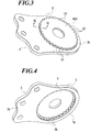
- the outer teeth gear 10 is made of metal and projects from the first hinge member 1.
- a metal plate 3 as a base material or a plate material is pressed from a back surface 3b, and a circular projection 5 having an outer diameter slightly greater than that of the outer teeth gear 10 to be formed is projected in an embossed manner.
- the reference numeral 5c represents an outer peripheral surface of the circular projection 5.
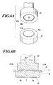
- a second step as shown in Fig. 6A, dies which have a die 51 and a punch 52 is used.
- the die 51 has a projection 51a on a end surface and concave surfaces 51b in a semicircular shape is formed at an equal distance in a periphery of the projection 51a.
- the punch 52 has a recess 52a defined by a peripheral wall in a end surface.
- the peripheral wall has mountain portions 52b therein at an equal distance and valley portions 52c formed between the mountain portions 52b.
- an outer peripheral portion 5a of the circular projection 5 is subjected to a press forming from a surface 3a of the plate material 3 by the mountain portions 52b and the valley portions 52c, and the outer peripheral portion 5a is pressed back by the concave surfaces 51b toward the back surface 3b at an equal distance.
- gear teeth 11 of the outer teeth gear 10 are formed around the outer peripheral portion 5a by the valley portions 52c and valleys 12 between gear teeth 11 are formed by the mountain portions 52b.
- the pressed portion of the outer peripheral portion 5a is projected toward the back surface 3b, and a connection portion 5b which is connected to an inner peripheral surface 7a of a circular recess 7 formed at the side of the back surface 3b of the circular projection 5 is formed.
- the outer teeth gear 10 is formed by extrusion from the metal plate material 3 as the base material, and has a tooth width tl which is thinner than a plate thickness T1 of the plate material 3, and the outer teeth gear 10 is integrally connected at its entire outer periphery to the plate material 3.
- the outer teeth gear 10 comprises the circular projection 5 which is previously formed by extrusion at the side of the surface 3a of the plate material 3, the gear teeth 11 formed around the outer peripheral portion 5a of this circular projection 5, and the connection portion 5b which projects toward the back surface 3b of the plate material 3 corresponding to valleys 12 of the gear teeth 11 and which is connected to the inner peripheral surface 7a of the circular recess 7 formed at the side of the back surface 3b of the circular projection 5.
- the first hinge member 1 is produced such that the metal plate material 3 which is the base material is extruded to form the outer teeth gear 10 and then, the plate material 3 is subjected to a predetermined cutting and drilling working.
- connection portion 5b is formed such as to project into a semi-cylindrical shape toward the back surface 3b of the circular projection 5, the connection portion 5b may be formed into a slope like connection portion 4d of the inner teeth gear 20 which will be explained later, or gear teeth only if the outer teeth gear 10 which is to be formed at the side of the surface 3a can be distinguished.
- the above explained outer teeth gear 10 is produced through two steps, i.e., the first step for extruding the circular projection 5 at the side of the surface 3a of the plate material 3, and the second step for press forming the gear teeth 11 around the outer peripheral portion 5a of this circular projection 5.
- the gear teeth 11 of this outer teeth gear 10 are formed by pressing back the outer peripheral portion 5a of the circular projection 5 which is formed by extrusion at the side of the surface 3a of the plate material 3 toward the back surface 3b of the plate material 3.
- the gear teeth 11 are press formed around the outer peripheral portion 5a of the circular projection 5, the portion of the circular projection 5 which is to be pressed is projected and escaped toward the back surface 3b of the plate material 3 and plastically deformed, and the connection portion 5b which is connected to the inner peripheral surface 7a of the circular recess 7 formed at the side of the back surface 3b is formed.
- this outer teeth gear 10 As compared with the conventional outer teeth gear which is produced by precision extrusion with only one step, forming pressure when the gear teeth 11 is formed is reduced. As a result, as shown in Fig. 7, a drawn portion 13 formed on tip end portion of each of the gear teeth 11 at the time of gear teeth formation is reduced, and the effective tooth width W1 of the gear teeth 11 is prevented from being reduced, and it is possible to make the plate thickness T1 of the plate material 3 as the base material can be made thinner correspondingly.
- connection portion 5b can be formed of only material which is required for securing the strength, waste of material can be reduced, and since composition (flow) of the material of the superposed portion 5d is continuous, its strength can be increased.
- the producing method of the outer teeth gear 10 comprises two steps, i.e., a first step in which the plate material 3 is pressed from the back surface 3b, thereby projecting the circular projection 5 having an outer diameter slightly greater than that of the outer teeth gear 10 to be formed in the embossed manner at the side of the surface 3a of the plate material 3, and a second step in which the outer peripheral portion 5a of this circular projection 5 is subjected to the press forming from the surface 3a of the plate material 3, the outer peripheral portion 5a of the circular projection 5 is pressed back toward the back surface 3b of the plate material at equal distances, thereby forming the gear teeth 11 of the outer teeth gear 10, so that the outer teeth gear 10 connected at its entire outer periphery to the plate material 3 is extruded from the plate material 3.
- the producing method of the outer teeth gear 10 of the present invention as compared with the conventional producing method of the outer teeth gear by precision extrusion with one step only, the forming pressure when the gear teeth 11 are formed can be reduced.
- the drawn portion 13 which is formed at the tip end portion of each of the gear teeth 11 at the time of formation of the gear teeth can be reduced, the effective tooth width W1 of the gear teeth 11 can be prevented from being reduced, and the plate thickness T1 of the base material can be made thinner correspondingly.
- the press formed circular projection 5 is formed such that its outer diameter is shaped into a substantially circular whose outer diameter is slightly greater than a diameter of the tip ends of the outer teeth gear 10 in the step 1.
- the structure of the press dies 31 and 32 used in the first step can be simplified.
- the costs for producing the press dies 31 and 32 can be reduced, and lifetime of the press dies 31 and 32 can be elongated and therefore, the producing costs of the outer teeth gear 10 can be reduced.
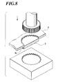
- Figs. 8 is an explanatory diagram showing another first step different from the first step shown in Fig. 5.
- the outer peripheral surface 5c of the circular projection 5 is formed into a corrugated shape corresponding to the number of teeth of the outer teeth gear 10.
- the producing method of the outer teeth gear 10 having the first step shown in Fig. 8 as compared with the producing method of the outer teeth gear 10 having the first step shown in Fig. 5, since the life time of the press dies 51 and 52 (see Fig. 6) used in the second step is elongated, the producing costs of the outer teeth gear 10 can be reduced, the drawn portion 13 formed at the tip end of the tooth of each of the gear teeth 11 at the time of formation of the gear teeth in the second step can further be reduced, and the plate thickness T1 of the base material can further be made thinner correspondingly.
- outer teeth gear 10 and its producing method can be used for the reclining mechanism of the vehicle seat
- the outer teeth gear 10 and its producing method of the present invention should not be limited to be used only for the reclining mechanism of the vehicle seat.
- Figs. 9 to 13 show a second embodiment which is one example of embodiments.
- the inner teeth gear 20 is used for the reclining mechanism 103 of the vehicle seat 100, and is recessed in the metal plate like second hinge member 2.
- a metal plate material 4 which is a base material is pressed from the side of a surface 4a, thereby forming a circular recess 6 having an inner diameter slightly smaller than that of the inner teeth gear 20 to be formed at the side of the surface 4a of the plate material 4 in the embossed manner.
- a surrounding portion 4c surrounding the circular recess 6 in the plate material 4 is subjected to press forming from the side of the surface 4a of the plate material 4 to a bottom surface 6b of the circular recess 6, and the surrounding portion 4c is intruded toward a back surface 4b of the plate material 4 at equal distances.
- the surrounding portion 4c including the inner peripheral surface 6a of the circular recess 6 is formed with gear teeth 21 of the inner teeth gear 20, a portion of the surrounding portion 4c which is pressed is projected toward the back surface 4b, and a connection portion 4d which is connected to an outer peripheral surface 8a of a circular projection 8 formed at the side of the back surface 4b of the circular recess 6.
- the inner teeth gear 20 is formed by intrusion forming in the metal plate material 4 which is the base material, and has a tooth width t2 which is thinner than a plate thickness T2 of the plate material, and is integrally connected at the entire outer periphery of the inner teeth gear 20 to the extruded portion 4e which is extruded from the plate material 4.
- the inner teeth gear 20 comprises the circular recess 6 which is previously formed by intrusion forming at the side of the back surface 4b of the plate material 4, the gear teeth 21 formed around the inner peripheral surface 6a of the circular recess 6 by intruding the surrounding portion 4c surrounding this circular recess 6 at equal distances, and the connection portion 4d which projects toward the back surface 4b of the plate material 4 corresponding to valleys 22 of the gear teeth 21 and which is connected to the outer peripheral surface 8a of the circular projection 8 formed at the side of the back surface 4b of the circular recess 6.
- the second hinge member 2 is produced such that the metal plate material 4 as the base material is intruded to form the inner teeth gear 20 and then, the plate material 4 is subjected to a predetermined cutting and drilling working.
- the above explained inner teeth gear 20 is produced through two steps, i.e., the first step for intruding the circular projection 6 at the side of the surface 4a of the plate material 4, and the second step for press forming the gear teeth 21 around the surrounding portion 4c surrounding the circular recess 6 in the plate material 4.
- the gear teeth 21 are formed by intruding the surrounding portion 4c surrounding the circular recess 6 which is formed by intrusion at the side of the surface 4a of the plate material 4 toward the back surface 4b. Therefore, when the gear teeth 21 is formed around the surrounding portion 4c surrounding the circular recess 6 in the plate material 4, the portion of the surrounding portion 4c which is pressed is projected and escaped toward the back surface 4b and is plastically deformed, and the connection portion 4d connected to the outer peripheral surface 8a of the circular projection 8 formed at the side of the back surface 4b is formed.
- the forming pressure when the gear teeth 21 are formed can be reduced.
- the drawn portion 23 which is formed at the tip end portion of each of the gear teeth 21 at the time of formation of the gear teeth can be reduced, the effective tooth width W2 of the gear teeth 21 can be prevented from being reduced, and the plate thickness T2 of plate material 4 which is the base material can be made thinner correspondingly.
- connection portion 4d since the portion of the surrounding portion 4c which is to be intruded in is moved toward the back surface 4b of the plate material 4 by plastic deformation, the connection portion 4d is formed, the remaining portion of the pressed surrounding portion 4c flows to a superposed portion 4f of the plate material 4 and the extruding portion 4e. Therefore, the connection portion 4d can be formed of only material which is required for securing the strength, waste of material can be reduced, and since composition (flow) of the material of the superposed portion 4d is continuous, its strength can be increased.
- the producing method of the inner teeth gear 20 comprises two steps, i.e., a first step in which the plate material 4 is pressed from the side of the surface 4a, thereby forming, in embossed manner, the circular recess 6 having the inner diameter smaller than that of the inner teeth gear 20 to be formed on the side of the surface 4a of the plate material 4, and a second step in which the surrounding portion 4c surrounding the circular recess 6 in the plate 4 is subjected to press forming from the side of the surface 4a of the plate material 4 to the bottom surface 6b of the circular recess 6, thereby intruding the surrounding portion 4c toward the back surface 4b of the plate material 4, and the gear teeth 21 of the inner teeth gear 20 are formed around the inner peripheral surface 6a of the circular recess 6, so that the inner teeth gear 20 connected at its entire outer periphery to the plate material 4 is formed by intrusion forming.
- the producing method of the inner teeth gear 20 of the present invention as compared with the conventional producing method of the inner teeth gear by precision intrusion with one step only, the forming pressure when the gear teeth 21 are formed can be reduced.
- the drawn portion 23 which is formed at the tip end portion of each of the gear teeth 21 at the time of formation of the gear teeth can be reduced, the effective tooth width W2 of the gear teeth 21 can be prevented from being reduced, and the plate thickness T2 of the plate material 4 as a base material can be made thinner correspondingly.
- the press formed circular projection 6 is formed such that its inner diameter is shaped into a substantially circular whose inner diameter is slightly smaller than a diameter of the tip ends of the inner teeth gear 20 in the step 1.
- the structure of the press dies 41 and 42 used in the first step can be simplified.
- the costs for producing the press dies 41 and 42 can be reduced, and lifetime of the press dies 41 and 42 can be elongated and therefore, the producing costs of the inner teeth gear 20 can be reduced.
- Figs. 14 is an explanatory diagram showing another first step different from the first step shown in Fig. 11.
- the inner peripheral surface 6a of the circular recess 6 is formed into a corrugated shape corresponding to the number of teeth of the inner teeth gear 20.
- the pressed amount of the plate material 4 which is pressed formed in the second step is reduced.
- the press forming pressure against the plate material 4 in the second step can further be reduced.
- the producing method of the inner teeth gear 20 having the first step shown in Fig. 14 as compared with the producing method of the inner teeth gear 20 having the first step shown in Fig. 11, since the life time of the press dies 61 and 62 (see Fig. 12) used in the second step is elongated, the producing costs of the inner teeth gear 20 can be reduced.
- the drawn portion 23 formed at the tip end of the tooth of each of the gear teeth 21 at the time of formation of the gear teeth in the second step can further be reduced, and the plate thickness T2 of the base material can further be made thinner correspondingly.
- the inner teeth gear 20 and its producing method can be used for the reclining mechanism 103 of the vehicle seat 100, the inner teeth gear 20 and its producing method of the present invention should not be limited to be used only for the reclining mechanism of the vehicle seat.
- Figs. 15 and 16 show outer and inner teeth gears of a comparative examples.
- An outer teeth gear 201 shown in Fig. 15 is formed by one time precision extrusion using press dies having a shape which is substantially the same as the outer teeth gear 201 from a metal plate material 202 which is a base material.
- a first hinge member 203 is formed by subjecting the plate material to a predetermined cutting and drilling works after the outer teeth gear 201 is formed.
- the outer teeth gear 201 is integrally connected at its entire outer periphery with the first hinge member 203, and an inner teeth gear 203a is formed on a back surface of each of the gear teeth 201a by extruding the outer teeth gear 201.
- An inner teeth gear 211 shown in Fig. 16 is formed by one time precision intrusion using press dies having a shape which is substantially the same as the inner teeth gear 211 from a metal plate material 212 which is a base material.
- a second hinge member 213 is formed by subjecting the plate material 212 to a predetermined cutting and drilling works after the inner teeth gear 211 is formed.
- the inner teeth gear 211 is integrally connected at its entire outer periphery with the second hinge member 213, and an outer teeth gear 213a is formed on a back surface of each of the gear teeth 211a by extruding the inner teeth gear 211.
- each of the gear teeth 201a of the outer teeth gear 201 which is formed at the time of extrusion forming is pressed by the press dies along its tooth shape, the opposite side from the pressed side is drawn by remaining portion to generate sags, and the sags of drawn portion 201b becomes greater as approaching the tip end of the tooth. Therefore, the effective tooth width W3 of each of the gear teeth 201a of the outer teeth gear 201 is reduced. Further, since a drawn portion 211b is likewise generated in the inner teeth gear 211, the effective tooth width W4 of each of the gear teeth 211a of the inner teeth gear 211 is also reduced. Therefore, meshing margins of the inner and outer gears 211 and 201 are reduced, and the meshing strength is lowered.
- the circular projection having gear teeth is formed by extrusion such as to shearing the plate material 212, although the superposed portion of the circular projection and the plate material 212 is connected to each other, composition (flow) of the base material of the superposed portion is not continuous, its strength is reduced.
- the inner teeth gear 203a is formed on the back surface of the outer teeth gear 201, this has nothing to do with strength almost at all, and the material is uses wastefully.
- the outer and inner teeth are formed using one sheet of plate, it is difficult to distinguish from each other, and there is a possibility that they may be assembled erroneously.
Landscapes
- Engineering & Computer Science (AREA)
- Mechanical Engineering (AREA)
- Aviation & Aerospace Engineering (AREA)
- Transportation (AREA)
- Gears, Cams (AREA)
- Shaping Metal By Deep-Drawing, Or The Like (AREA)
- Chairs For Special Purposes, Such As Reclining Chairs (AREA)
Applications Claiming Priority (2)
| Application Number | Priority Date | Filing Date | Title |
|---|---|---|---|
| JP4239798 | 1998-02-24 | ||
| JP10042397A JPH11236957A (ja) | 1998-02-24 | 1998-02-24 | 外歯及び内歯ギヤ並びにその製造方法 |
Publications (2)
| Publication Number | Publication Date |
|---|---|
| EP0937523A2 true EP0937523A2 (fr) | 1999-08-25 |
| EP0937523A3 EP0937523A3 (fr) | 2001-04-18 |
Family
ID=12634943
Family Applications (1)
| Application Number | Title | Priority Date | Filing Date |
|---|---|---|---|
| EP99301343A Withdrawn EP0937523A3 (fr) | 1998-02-24 | 1999-02-24 | Procédé de fabrication de dentures intérieures et extérieures |
Country Status (3)
| Country | Link |
|---|---|
| EP (1) | EP0937523A3 (fr) |
| JP (1) | JPH11236957A (fr) |
| KR (1) | KR100287269B1 (fr) |
Cited By (4)
| Publication number | Priority date | Publication date | Assignee | Title |
|---|---|---|---|---|
| EP1900452A1 (fr) * | 2006-09-13 | 2008-03-19 | Feintool Intellectual Property AG | Procédé de renforcement d'un paroi d'une garniture tridimensionnelle |
| DE102007001782A1 (de) * | 2006-09-05 | 2008-03-20 | Johnson Controls Gmbh | Verstellvorrichtung mit zwei verzahnten Bauteilen und Verfahren zur Herstellung der verzahnten Bauteile |
| WO2017050403A1 (fr) * | 2015-09-22 | 2017-03-30 | Daimler Ag | Procédé de fabrication d'un élément d'accouplement pour un accouplement à griffes constitué d'une pièce de tôle épaisse et élément d'accouplement |
| US10974302B2 (en) | 2017-05-26 | 2021-04-13 | Toyota Boshoku Kabushiki Kaisha | Manufacturing method for cylindrical portion |
Families Citing this family (5)
| Publication number | Priority date | Publication date | Assignee | Title |
|---|---|---|---|---|
| JP4433649B2 (ja) * | 2001-09-28 | 2010-03-17 | トヨタ紡織株式会社 | フランジを備えた製品の成形方法 |
| KR100472186B1 (ko) * | 2002-05-31 | 2005-03-08 | 주식회사 윤 영 | 고강성 차량용 리클라이너 |
| JP4131650B2 (ja) * | 2002-07-24 | 2008-08-13 | シロキ工業株式会社 | リクライニング機構のラチェット、その製造方法及びリクライニング機構のラチェットの形成金型 |
| CN103737334B (zh) * | 2014-01-26 | 2015-12-30 | 无锡市神力齿轮冷挤有限公司 | 高强度齿轮加工工艺 |
| JP2021159962A (ja) * | 2020-03-31 | 2021-10-11 | 株式会社ミクニ | 内歯車の製造方法、内歯車及び波動歯車装置 |
Family Cites Families (3)
| Publication number | Priority date | Publication date | Assignee | Title |
|---|---|---|---|---|
| DE2807516A1 (de) * | 1978-02-22 | 1979-08-23 | Selzer Fertigungstech | Verfahren zur spanlosen kaltformung eines innenverzahnten metall-werkstueckes, insbesondere eines sitzbeschlagteiles eines kraftfahrzeugsitzes und nach dem verfahren hergestellter gegenstand |
| DE2834492C3 (de) * | 1978-08-07 | 1994-07-28 | Keiper Recaro Gmbh Co | Gelenkbeschlag für einen Sitz mit verstellbarer Rückenlehne, insbesondere Kraftfahrzeugsitz |
| DE4140720C2 (de) * | 1991-12-10 | 1995-10-12 | Naue Johnson Controls Eng | Verfahren zur Herstellung von Stirnrädern und zugehörigen Innenzahnkränzen durch kombinierte Feinstanz- und Fließpreßarbeitsgänge |
-
1998
- 1998-02-24 JP JP10042397A patent/JPH11236957A/ja active Pending
-
1999
- 1999-02-24 KR KR1019990006101A patent/KR100287269B1/ko not_active Expired - Fee Related
- 1999-02-24 EP EP99301343A patent/EP0937523A3/fr not_active Withdrawn
Cited By (6)
| Publication number | Priority date | Publication date | Assignee | Title |
|---|---|---|---|---|
| DE102007001782A1 (de) * | 2006-09-05 | 2008-03-20 | Johnson Controls Gmbh | Verstellvorrichtung mit zwei verzahnten Bauteilen und Verfahren zur Herstellung der verzahnten Bauteile |
| DE102007001782B4 (de) * | 2006-09-05 | 2009-02-26 | Johnson Controls Gmbh | Verfahren zur Herstellung verzahnter Bauteile einer Verstellvorrichtung |
| EP1900452A1 (fr) * | 2006-09-13 | 2008-03-19 | Feintool Intellectual Property AG | Procédé de renforcement d'un paroi d'une garniture tridimensionnelle |
| US7581424B2 (en) | 2006-09-13 | 2009-09-01 | Feintool Intellectual Property Ag | Method for the reinforcement of a wall region of a three-dimensional attachment |
| WO2017050403A1 (fr) * | 2015-09-22 | 2017-03-30 | Daimler Ag | Procédé de fabrication d'un élément d'accouplement pour un accouplement à griffes constitué d'une pièce de tôle épaisse et élément d'accouplement |
| US10974302B2 (en) | 2017-05-26 | 2021-04-13 | Toyota Boshoku Kabushiki Kaisha | Manufacturing method for cylindrical portion |
Also Published As
| Publication number | Publication date |
|---|---|
| KR19990072897A (ko) | 1999-09-27 |
| JPH11236957A (ja) | 1999-08-31 |
| EP0937523A3 (fr) | 2001-04-18 |
| KR100287269B1 (ko) | 2001-04-16 |
Similar Documents
| Publication | Publication Date | Title |
|---|---|---|
| EP0937523A2 (fr) | Procédé de fabrication de dentures intérieures et extérieures | |
| JP3708175B2 (ja) | ロールホーミング金型 | |
| US4469376A (en) | Hinge, particularly for seat with adjustable back rest and method of manufacturing the same | |
| EP1057980A2 (fr) | Culbuteur et son procédé de fabrication | |
| EP2116413B1 (fr) | Mécanisme de réglage de position angulaire | |
| CN1081945A (zh) | 尤其用于汽车座椅调节的齿盘的制造方法 | |
| JPH0225602B2 (fr) | ||
| JP3357422B2 (ja) | プレス機械による剪断加工方法 | |
| JP4385719B2 (ja) | ボス付き歯車状部材の成形方法及びボス付き歯車状部材 | |
| JPS63285366A (ja) | 遊星歯車 | |
| JP3696714B2 (ja) | 内歯・外歯を有する一体型ドラム成形方法 | |
| JPH06102227B2 (ja) | ラチェット歯を備えた板金部品の製造方法 | |
| JP2885035B2 (ja) | プレス加工による局部肉厚増加方法 | |
| JP6859853B2 (ja) | 凹凸材の製造方法 | |
| JP3264140B2 (ja) | 内歯車の製造方法及び内歯車の矯正金型 | |
| JP3892675B2 (ja) | 自動変速機用ピストン及びその製法 | |
| JPS5847929B2 (ja) | 歯車の冷間成形法 | |
| CN215032885U (zh) | 一种汽车门外板模具 | |
| JP3342343B2 (ja) | 油孔付き歯車及びその製造方法 | |
| KR101446699B1 (ko) | 3차원 바디의 벽 부분을 보강하는 방법 | |
| JPH0681906A (ja) | ダブルプラネタリキャリア | |
| JPH0952140A (ja) | 歯車及びその製造方法 | |
| JPS60174220A (ja) | ウエルト用芯材の製造装置 | |
| JPH07289388A (ja) | シートバックフレーム、補強材付シートバックフレーム及びそれらの製法 | |
| JPH08168815A (ja) | 金属製押出型材の押出工具 |
Legal Events
| Date | Code | Title | Description |
|---|---|---|---|
| PUAI | Public reference made under article 153(3) epc to a published international application that has entered the european phase |
Free format text: ORIGINAL CODE: 0009012 |
|
| AK | Designated contracting states |
Kind code of ref document: A2 Designated state(s): AT BE CH CY DE DK ES FI FR GB GR IE IT LI LU MC NL PT SE |
|
| AX | Request for extension of the european patent |
Free format text: AL;LT;LV;MK;RO;SI |
|
| PUAL | Search report despatched |
Free format text: ORIGINAL CODE: 0009013 |
|
| AK | Designated contracting states |
Kind code of ref document: A3 Designated state(s): AT BE CH CY DE DK ES FI FR GB GR IE IT LI LU MC NL PT SE |
|
| AX | Request for extension of the european patent |
Free format text: AL;LT;LV;MK;RO;SI |
|
| RIC1 | Information provided on ipc code assigned before grant |
Free format text: 7B 21K 1/30 A, 7B 21D 53/28 B, 7B 60N 2/225 B |
|
| AKX | Designation fees paid | ||
| REG | Reference to a national code |
Ref country code: DE Ref legal event code: 8566 |
|
| STAA | Information on the status of an ep patent application or granted ep patent |
Free format text: STATUS: THE APPLICATION IS DEEMED TO BE WITHDRAWN |
|
| 18D | Application deemed to be withdrawn |
Effective date: 20011019 |