EP0937526A1 - Porte-outils pour plaquette de coupe à enlèvement de copeaux - Google Patents
Porte-outils pour plaquette de coupe à enlèvement de copeaux Download PDFInfo
- Publication number
- EP0937526A1 EP0937526A1 EP98124717A EP98124717A EP0937526A1 EP 0937526 A1 EP0937526 A1 EP 0937526A1 EP 98124717 A EP98124717 A EP 98124717A EP 98124717 A EP98124717 A EP 98124717A EP 0937526 A1 EP0937526 A1 EP 0937526A1
- Authority
- EP
- European Patent Office
- Prior art keywords
- bore
- holder
- clamping
- holder according
- slot
- Prior art date
- Legal status (The legal status is an assumption and is not a legal conclusion. Google has not performed a legal analysis and makes no representation as to the accuracy of the status listed.)
- Granted
Links
- 230000005540 biological transmission Effects 0.000 claims description 24
- 230000007704 transition Effects 0.000 claims description 2
- 230000004308 accommodation Effects 0.000 abstract 3
- 241000047428 Halter Species 0.000 description 3
- 241000237858 Gastropoda Species 0.000 description 1
- 238000005452 bending Methods 0.000 description 1
- 230000000295 complement effect Effects 0.000 description 1
- 238000006073 displacement reaction Methods 0.000 description 1
- 238000005516 engineering process Methods 0.000 description 1
- 230000002349 favourable effect Effects 0.000 description 1
- 238000007373 indentation Methods 0.000 description 1
- 230000037431 insertion Effects 0.000 description 1
- 238000003780 insertion Methods 0.000 description 1
- 238000004519 manufacturing process Methods 0.000 description 1
- 238000000926 separation method Methods 0.000 description 1
- 230000003319 supportive effect Effects 0.000 description 1
Images


Classifications
-
- B—PERFORMING OPERATIONS; TRANSPORTING
- B23—MACHINE TOOLS; METAL-WORKING NOT OTHERWISE PROVIDED FOR
- B23B—TURNING; BORING
- B23B27/00—Tools for turning or boring machines; Tools of a similar kind in general; Accessories therefor
- B23B27/04—Cutting-off tools
-
- B—PERFORMING OPERATIONS; TRANSPORTING
- B23—MACHINE TOOLS; METAL-WORKING NOT OTHERWISE PROVIDED FOR
- B23B—TURNING; BORING
- B23B2205/00—Fixation of cutting inserts in holders
- B23B2205/02—Fixation using an elastically deformable clamping member
-
- Y—GENERAL TAGGING OF NEW TECHNOLOGICAL DEVELOPMENTS; GENERAL TAGGING OF CROSS-SECTIONAL TECHNOLOGIES SPANNING OVER SEVERAL SECTIONS OF THE IPC; TECHNICAL SUBJECTS COVERED BY FORMER USPC CROSS-REFERENCE ART COLLECTIONS [XRACs] AND DIGESTS
- Y10—TECHNICAL SUBJECTS COVERED BY FORMER USPC
- Y10T—TECHNICAL SUBJECTS COVERED BY FORMER US CLASSIFICATION
- Y10T407/00—Cutters, for shaping
- Y10T407/22—Cutters, for shaping including holder having seat for inserted tool
- Y10T407/2272—Cutters, for shaping including holder having seat for inserted tool with separate means to fasten tool to holder
- Y10T407/2282—Cutters, for shaping including holder having seat for inserted tool with separate means to fasten tool to holder including tool holding clamp and clamp actuator
- Y10T407/2286—Resiliently biased clamp jaw
-
- Y—GENERAL TAGGING OF NEW TECHNOLOGICAL DEVELOPMENTS; GENERAL TAGGING OF CROSS-SECTIONAL TECHNOLOGIES SPANNING OVER SEVERAL SECTIONS OF THE IPC; TECHNICAL SUBJECTS COVERED BY FORMER USPC CROSS-REFERENCE ART COLLECTIONS [XRACs] AND DIGESTS
- Y10—TECHNICAL SUBJECTS COVERED BY FORMER USPC
- Y10T—TECHNICAL SUBJECTS COVERED BY FORMER US CLASSIFICATION
- Y10T407/00—Cutters, for shaping
- Y10T407/22—Cutters, for shaping including holder having seat for inserted tool
- Y10T407/2272—Cutters, for shaping including holder having seat for inserted tool with separate means to fasten tool to holder
- Y10T407/2282—Cutters, for shaping including holder having seat for inserted tool with separate means to fasten tool to holder including tool holding clamp and clamp actuator
- Y10T407/2286—Resiliently biased clamp jaw
- Y10T407/2288—Integral with holder
-
- Y—GENERAL TAGGING OF NEW TECHNOLOGICAL DEVELOPMENTS; GENERAL TAGGING OF CROSS-SECTIONAL TECHNOLOGIES SPANNING OVER SEVERAL SECTIONS OF THE IPC; TECHNICAL SUBJECTS COVERED BY FORMER USPC CROSS-REFERENCE ART COLLECTIONS [XRACs] AND DIGESTS
- Y10—TECHNICAL SUBJECTS COVERED BY FORMER USPC
- Y10T—TECHNICAL SUBJECTS COVERED BY FORMER US CLASSIFICATION
- Y10T407/00—Cutters, for shaping
- Y10T407/22—Cutters, for shaping including holder having seat for inserted tool
- Y10T407/2272—Cutters, for shaping including holder having seat for inserted tool with separate means to fasten tool to holder
- Y10T407/2282—Cutters, for shaping including holder having seat for inserted tool with separate means to fasten tool to holder including tool holding clamp and clamp actuator
- Y10T407/229—Pivoted jaw
-
- Y—GENERAL TAGGING OF NEW TECHNOLOGICAL DEVELOPMENTS; GENERAL TAGGING OF CROSS-SECTIONAL TECHNOLOGIES SPANNING OVER SEVERAL SECTIONS OF THE IPC; TECHNICAL SUBJECTS COVERED BY FORMER USPC CROSS-REFERENCE ART COLLECTIONS [XRACs] AND DIGESTS
- Y10—TECHNICAL SUBJECTS COVERED BY FORMER USPC
- Y10T—TECHNICAL SUBJECTS COVERED BY FORMER US CLASSIFICATION
- Y10T407/00—Cutters, for shaping
- Y10T407/24—Cutters, for shaping with chip breaker, guide or deflector
- Y10T407/245—Cutters, for shaping with chip breaker, guide or deflector comprising concave surface in cutting face of tool
-
- Y—GENERAL TAGGING OF NEW TECHNOLOGICAL DEVELOPMENTS; GENERAL TAGGING OF CROSS-SECTIONAL TECHNOLOGIES SPANNING OVER SEVERAL SECTIONS OF THE IPC; TECHNICAL SUBJECTS COVERED BY FORMER USPC CROSS-REFERENCE ART COLLECTIONS [XRACs] AND DIGESTS
- Y10—TECHNICAL SUBJECTS COVERED BY FORMER USPC
- Y10T—TECHNICAL SUBJECTS COVERED BY FORMER US CLASSIFICATION
- Y10T407/00—Cutters, for shaping
- Y10T407/25—Cutters, for shaping including cut off tool
Definitions
- the invention relates to a holder for cutting tool inserts, in particular lancing or cutting inserts, with an approximation beam-shaped cutter carrier, one end formed in this Recess that serves as a receiving pocket for the inserts and through which the jaws defining the clear width of the receiving pocket is limited, one from the side edge of the cutter holder to close to the inside Termination of the receiving pocket extending slot to allow a elastic pivoting mobility of one of the clamping jaws and with one Clamping device for generating a in the area of the slot on the pivoting jaw acting clamping force a rotatably mounted Has actuator.
- the invention has for its object to a holder of the type in question create, even at high, generated by the clamping device Clamping force there is no danger that disruptive shear force components on the attack the movable jaw.
- this object is the invention solved in that the actuator receiving bore in a distance from the slot and that the clamping force from Actuator on the movable jaw transmitting power transmission member is slidably guided in the cutter holder.
- the force transmission element is in the cutter holder in a second hole, the axis runs at an angle to the axis of the first hole and this in one Distance from the slot cuts.
- the actuator of the clamping device can be in the form of an eccentric be provided, being a force transmission element on the one hand on the radius the eccentric and on the other hand more supportive on the movable jaw Pen can be provided.
- a rotatable one can also be used
- Cams can be provided with a cam surface of low pitch, for example in the form of a snail with a linear pitch.
- the first bore with an internal thread for an actuator the clamping device serving clamping screw be provided forms a cone at its end region protruding into the second bore, which in cooperation with the power transmission element guided in the second bore a force component displacing this along the second bore generated.
- one can act as a force transmission element on the one hand on the cone Clamping screw and on the other hand supporting on the movable clamping jaw Ball may be provided.
- a pin supported on the cone could also be used instead of a ball.
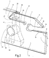
- FIG. 1 and FIG. 2 show the front part of a cutter holder 1, respectively without a tool insert to be clamped to it.
- the cutter holder 1 has in its front end region 3 a receiving pocket 5 in the form of a towards the front open breakthrough.
- the breakthrough has one at its inner end Extension 7 on.
- the front area is the clear width of the receiving pocket 5 through two jaws 9 and 11 limited, the mutually facing clamping surfaces Form 13 and 15, between which a relevant tool insert, not shown can be clamped.
- the clamping surfaces 13, 15 each have a V-shaped longitudinal groove 17 or 19, a local depression 21 being worked into the latter. This shape the clamping surfaces 13, 15 is used for the exact positioning of this complementary contouring provided tool insert.
- the cutting tool holder has 5 lancing inserts in its front end portion 3 a smaller width than in its rear Beam part 23, the transition between the narrow end region 3 and the beam part 23 is formed by a slightly curved shoulder surface 25 is.
- Starting from one the inner end of extension 7 of the receiving pocket 5 adjacent opening 27 extends continuously in the cutter holder 1 trained slot 29 in a straight line into the beam part 23 in substantially parallel to the upper side edge thereof up to one in FIG. 1 and 2, designated 31, where the rectilinear portion of the slot 29 ends and this assumes a course obliquely upwards and forwards and finally at the upper edge of the beam part 23 of the cutter holder 1 ends at 33.
- a clamping device 35 for generating a clamping force for generating a clamping force, the widens the slot 29 in its rear area adjacent to the point 31, in order to pivot the jaw 11 are shown in Figs. 1 and 3.
- Actuator of the clamping device 35 is on a pivot pin 37 trained eccentric 45 provided.
- the pivot 37 is in one Beam part 23 of the cutter holder 1 formed cross bore 39 rotatable stored.
- a second hole 41 extending from the lower edge of the beam part 23 extends continuously to the slot 29, where it adjoins the point 31 opens, the transverse bore 39 intersects at right angles in its central area.
- the section of the bore 41 between the transverse bore 39 and the Slot 29 forms a guide in which a power transmission pin 43 is longitudinally displaceable is recorded.
- the pin 43 is based on the one hand on the radius of the Eccentric 45 (see in particular FIG. 3) and on the other hand at the point 31 adjacent rear part 47 of the movable part delimiting the slot 29 Jaw 11 off.
- the eccentric 45 is formed by an annular groove which is in the circumference of the circular cylindrical Pivot 37, offset to its axis of rotation, as a recess is incorporated.
- pivot pin 37 has a Torx or hexagon socket 48.
- the power transmission pin 43 insertable from the lower, open end of the bore 41. So that the pivot pin 37 can then be inserted into the transverse bore 39, has the pivot pin 37 in the wall parts 49 which form the eccentric 45 Limit the ring groove laterally, openings 51, which are in a suitable rotary position of the pivot 37 whose introduction the transverse bore 39 after Allow insertion of the power transmission pin 43.
- a further bore 53 extending parallel to the bore 41 is tangent the transverse bore 39 in the central area, in which when inserted Pivot 37 is the recessed annular groove forming the eccentric 45.
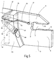
- FIGS. 4 and 5 show a second embodiment, in which as a rotatable Actuator of the clamping device, a clamping screw 57 is provided, which sits in an internally threaded bore 59.
- Hole 59 extends at an angle to a as a guide for the power transmission member serving second bore 61, the bores 59 and Cut 61 near slot 29.
- the outer mouth of the hole 59 is located on the shoulder surface 25, which is the paragraph between the narrow front end portion 3 and the rear beam part 23 of the Knife holder 1 forms.
- the clamping screw 57 has a cone 65, which in the second bore 61 protrudes.
- a ball 63 provided as a force transmission member is supported on the one hand on the cone 65 and on the other hand on the underside of the rear Part 47 of the movable jaw 11 from. To fall out the ball 63 out of the bore 61 with the clamping screw 57 unscrewed To prevent a locking pin 75 in a tangent to the bore 61, below the ball 63 transverse securing bore 73 is used.
- the operation of the second embodiment corresponds to that of first example.
- the clamping screw 57 By screwing in the clamping screw 57, the Circumferential surface of the end cone '65 a clamping force in cooperation with the ball 63, which is guided in the bore 61, so that on the part 47 of the movable jaw 11 only a force component with longitudinal the axis of the bore 61 extending line of action, so without any Shear force component is applied.
- the clamping device is self-locking, i.e. the resilience with which a concerned Tool insert (not shown) clamped in the receiving pocket 5 is only by unscrewing the clamping screw 57 can be canceled.
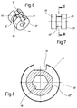
- FIGS. 6 to 8 relate to a third embodiment of the invention Holder.
- This embodiment differs from the first described Embodiment according to FIGS. 1 to 3 only by a modified Embodiment of the actuator of the clamping device.
- the actuator has one Pivot 37 on which is rotatable in the transverse bore 39 of the cutter holder 1 is stored.
- the forms between the wall parts 49 as an indentation, there is no circular groove, axially offset eccentric, but a cam 45 '.
- the cam 45 ' has a circumferential cam surface Slight slope on, starting from the aligned with the openings 51 Area of smallest radius', as a worm with a linear pitch above extends an angular range of 320 °.
Landscapes
- Engineering & Computer Science (AREA)
- Mechanical Engineering (AREA)
- Gripping On Spindles (AREA)
- Cutting Tools, Boring Holders, And Turrets (AREA)
Applications Claiming Priority (2)
| Application Number | Priority Date | Filing Date | Title |
|---|---|---|---|
| DE19807498A DE19807498A1 (de) | 1998-02-21 | 1998-02-21 | Halter für spanabhebende Werkzeug-Einsätze |
| DE19807498 | 1998-02-21 |
Publications (2)
| Publication Number | Publication Date |
|---|---|
| EP0937526A1 true EP0937526A1 (fr) | 1999-08-25 |
| EP0937526B1 EP0937526B1 (fr) | 2001-06-13 |
Family
ID=7858612
Family Applications (1)
| Application Number | Title | Priority Date | Filing Date |
|---|---|---|---|
| EP98124717A Expired - Lifetime EP0937526B1 (fr) | 1998-02-21 | 1998-12-28 | Porte-outils pour plaquette de coupe à enlèvement de copeaux |
Country Status (4)
| Country | Link |
|---|---|
| US (1) | US6139227A (fr) |
| EP (1) | EP0937526B1 (fr) |
| AT (1) | ATE202024T1 (fr) |
| DE (2) | DE19807498A1 (fr) |
Cited By (5)
| Publication number | Priority date | Publication date | Assignee | Title |
|---|---|---|---|---|
| WO2009135592A1 (fr) * | 2008-05-09 | 2009-11-12 | Hartmetall-Werkzeugfabrik Paul Horn Gmbh | Elément de maintien pour insert d’outil de retrait de copeaux |
| CN103732338A (zh) * | 2011-06-14 | 2014-04-16 | 硬质金属工具厂保罗霍恩有限公司 | 用于切割装置的固定装置 |
| CN103987479A (zh) * | 2011-12-08 | 2014-08-13 | 伊斯卡有限公司 | 用于将切削刀片夹持在其中的工具保持器和方法 |
| WO2017198759A1 (fr) * | 2016-05-20 | 2017-11-23 | Hartmetall-Werkzeugfabrik Paul Horn Gmbh | Support pour un outil d'usinage par enlèvement de copeaux, en particulier pour un outil de tournage longitudinal |
| TWI884218B (zh) * | 2020-06-23 | 2025-05-21 | 以色列商艾斯卡公司 | 具有嵌件接收凹穴及固定孔的刀具接頭、及切削刀具總成 |
Families Citing this family (19)
| Publication number | Priority date | Publication date | Assignee | Title |
|---|---|---|---|---|
| SE513633C2 (sv) * | 1999-02-02 | 2000-10-09 | Sandvik Ab | Verktyg för avstickning och liknande operationer |
| DE50110198D1 (de) * | 2000-03-16 | 2006-08-03 | Sandvik Intellectual Property | Schneidplattenhalter für Drehwerkzeuge sowie Stechplatten hierfür |
| SE522930C2 (sv) * | 2001-04-24 | 2004-03-16 | Sandvik Ab | Skärverktyg för avsticknings- och spårstickningsändamål med en spännmekanism innefattande dragstång och spännskruv |
| DE10126043A1 (de) * | 2001-05-29 | 2002-12-12 | Horn P Hartmetall Werkzeugfab | Bohrstange |
| US6708858B2 (en) * | 2002-06-06 | 2004-03-23 | Blanking Systems, Inc. | Clamp pieces for lower frame assembly of blanking tool |
| DE10224127C1 (de) * | 2002-05-29 | 2003-12-24 | Ernst Graf Gmbh | Halter für ein Drehwerkzeug, insbesondere für einen Abstechstahl |
| JP4407503B2 (ja) * | 2004-12-16 | 2010-02-03 | 三菱マテリアル株式会社 | 切削インサートのクランプ機構 |
| JP4867661B2 (ja) | 2006-03-02 | 2012-02-01 | 三菱マテリアル株式会社 | インサート着脱式切削工具 |
| JP5028883B2 (ja) * | 2006-06-30 | 2012-09-19 | 三菱マテリアル株式会社 | インサート着脱式切削工具 |
| IL191520A (en) * | 2008-05-18 | 2012-04-30 | Iscar Ltd | Cutting tool and cutting tool for it |
| IL203014A (en) * | 2009-12-29 | 2013-03-24 | Iscar Ltd | Cutting tool and cutting insert therefor |
| US8647023B2 (en) * | 2011-04-04 | 2014-02-11 | Kennametal Inc. | Clamping mechanism for slotting cutter |
| JP5961690B2 (ja) | 2011-08-02 | 2016-08-02 | イスカーリミテッド | 切削工具およびそれに対して切削インサートを保持するためのクランプ固定機構 |
| DE102012111240A1 (de) * | 2012-11-21 | 2014-05-22 | Hartmetall-Werkzeugfabrik Paul Horn Gmbh | Spanabhebendes Werkzeug |
| US9656326B2 (en) | 2013-04-24 | 2017-05-23 | Iscar, Ltd. | Tool holder having a clamping member with a non-circular cross-section and method for clamping a cutting insert therein |
| DE102016205658B3 (de) * | 2016-04-06 | 2017-09-07 | Gühring KG | Schneidwerkzeug mit einem an einem trägerkörper durch eine spannpratze lösbar befestigtem schneidkörper |
| WO2020230754A1 (fr) * | 2019-05-13 | 2020-11-19 | 京セラ株式会社 | Élément de serrage, machine-outil et procédé de production d'une pièce découpée |
| US12109632B2 (en) | 2021-09-22 | 2024-10-08 | Iscar, Ltd. | Tool holder with upper and lower jaws defining an insert receiving pocket and cutting tool |
| CN115647408A (zh) * | 2022-11-01 | 2023-01-31 | 东莞市高冶切削工具有限公司 | 一种快锁多功能技术车刀 |
Citations (7)
| Publication number | Priority date | Publication date | Assignee | Title |
|---|---|---|---|---|
| FR2373349A1 (fr) * | 1976-12-13 | 1978-07-07 | Impero Spa | Outil de coupe a insertion du taillant |
| EP0095062A1 (fr) * | 1982-05-21 | 1983-11-30 | Karl Zinner | Outil d'usinage avec plaquette de coupe serrée |
| DE3301919A1 (de) * | 1983-01-21 | 1984-07-26 | Werner 6967 Buchen Keller | Vorrichtung zur klemmenden befestigung von schneideinsaetzen |
| SU1284716A1 (ru) * | 1985-01-02 | 1987-01-23 | Горьковский Автомобильный Завод | Отрезной блок |
| DE8804365U1 (de) * | 1988-03-31 | 1988-05-11 | Kemmer, Klaus, Ing.(grad.), 7277 Wildberg | Schneid- und Abstechwerkzeug |
| DE8915043U1 (de) * | 1988-12-29 | 1990-05-03 | Böhler AG, 4005 Meerbusch | Klemmhalter für Zweischneiden-Wendeschneidplatten |
| CH685680A5 (fr) * | 1991-12-23 | 1995-09-15 | Stellram Sa | Outil de coupe à plaquettes amovibles. |
Family Cites Families (7)
| Publication number | Priority date | Publication date | Assignee | Title |
|---|---|---|---|---|
| US2825959A (en) * | 1951-05-26 | 1958-03-11 | Wesson Multicut Company | Tool holder |
| US4321846A (en) * | 1980-04-18 | 1982-03-30 | The Gillette Company | Tool holder |
| EP0259897B1 (fr) * | 1982-04-15 | 1992-10-14 | Sumitomo Wiring Systems, Ltd. | Système de jonction électrique |
| SE9004032L (sv) * | 1990-12-18 | 1992-06-19 | Sandvik Ab | Skaerverktyg |
| SE504314C2 (sv) * | 1992-04-28 | 1997-01-13 | Sandvik Ab | Skärförsett verktyg för avstickning eller liknande svarvningsoperationer samt underläggselement för skär till dylika verktyg |
| US5516241A (en) * | 1994-06-27 | 1996-05-14 | Valenite Inc. | Holder blade |
| SE511928C2 (sv) * | 1997-03-19 | 1999-12-20 | Sandvik Ab | Anordning samt förfarande för fastspänning av skär |
-
1998
- 1998-02-21 DE DE19807498A patent/DE19807498A1/de not_active Withdrawn
- 1998-12-28 AT AT98124717T patent/ATE202024T1/de active
- 1998-12-28 DE DE59800841T patent/DE59800841D1/de not_active Expired - Lifetime
- 1998-12-28 EP EP98124717A patent/EP0937526B1/fr not_active Expired - Lifetime
-
1999
- 1999-02-18 US US09/251,738 patent/US6139227A/en not_active Expired - Lifetime
Patent Citations (7)
| Publication number | Priority date | Publication date | Assignee | Title |
|---|---|---|---|---|
| FR2373349A1 (fr) * | 1976-12-13 | 1978-07-07 | Impero Spa | Outil de coupe a insertion du taillant |
| EP0095062A1 (fr) * | 1982-05-21 | 1983-11-30 | Karl Zinner | Outil d'usinage avec plaquette de coupe serrée |
| DE3301919A1 (de) * | 1983-01-21 | 1984-07-26 | Werner 6967 Buchen Keller | Vorrichtung zur klemmenden befestigung von schneideinsaetzen |
| SU1284716A1 (ru) * | 1985-01-02 | 1987-01-23 | Горьковский Автомобильный Завод | Отрезной блок |
| DE8804365U1 (de) * | 1988-03-31 | 1988-05-11 | Kemmer, Klaus, Ing.(grad.), 7277 Wildberg | Schneid- und Abstechwerkzeug |
| DE8915043U1 (de) * | 1988-12-29 | 1990-05-03 | Böhler AG, 4005 Meerbusch | Klemmhalter für Zweischneiden-Wendeschneidplatten |
| CH685680A5 (fr) * | 1991-12-23 | 1995-09-15 | Stellram Sa | Outil de coupe à plaquettes amovibles. |
Non-Patent Citations (1)
| Title |
|---|
| DATABASE WPI Section PQ Week 8735, 9 September 1987 Derwent World Patents Index; Class P54, AN 87-249039, XP002095637 * |
Cited By (10)
| Publication number | Priority date | Publication date | Assignee | Title |
|---|---|---|---|---|
| WO2009135592A1 (fr) * | 2008-05-09 | 2009-11-12 | Hartmetall-Werkzeugfabrik Paul Horn Gmbh | Elément de maintien pour insert d’outil de retrait de copeaux |
| DE102008023767A1 (de) | 2008-05-09 | 2009-11-12 | Hartmetall-Werkzeugfabrik Paul Horn Gmbh | Halter für einen spanabhebenden Werkzeugeinsatz |
| US8491232B2 (en) | 2008-05-09 | 2013-07-23 | Hartmetall-Werkzeugfabrik Paul Horn Gmbh | Holder for a chip-removing tool insert |
| CN103732338A (zh) * | 2011-06-14 | 2014-04-16 | 硬质金属工具厂保罗霍恩有限公司 | 用于切割装置的固定装置 |
| CN103732338B (zh) * | 2011-06-14 | 2016-09-07 | 硬质金属工具厂保罗霍恩有限公司 | 用于切割装置的固定装置 |
| US9468976B2 (en) | 2011-06-14 | 2016-10-18 | Hartmetall-Werkzeugfabrik Paul Horn Gmbh | Holder for a cutting device |
| CN103987479A (zh) * | 2011-12-08 | 2014-08-13 | 伊斯卡有限公司 | 用于将切削刀片夹持在其中的工具保持器和方法 |
| WO2017198759A1 (fr) * | 2016-05-20 | 2017-11-23 | Hartmetall-Werkzeugfabrik Paul Horn Gmbh | Support pour un outil d'usinage par enlèvement de copeaux, en particulier pour un outil de tournage longitudinal |
| US10556272B2 (en) | 2016-05-20 | 2020-02-11 | Hartmetall-Werkzeugfabrik Paul Horn Gmbh | Holder for a tool for material-removing machining, in particular for a longitudinal turning tool |
| TWI884218B (zh) * | 2020-06-23 | 2025-05-21 | 以色列商艾斯卡公司 | 具有嵌件接收凹穴及固定孔的刀具接頭、及切削刀具總成 |
Also Published As
| Publication number | Publication date |
|---|---|
| US6139227A (en) | 2000-10-31 |
| ATE202024T1 (de) | 2001-06-15 |
| EP0937526B1 (fr) | 2001-06-13 |
| DE59800841D1 (de) | 2001-07-19 |
| DE19807498A1 (de) | 1999-09-02 |
Similar Documents
| Publication | Publication Date | Title |
|---|---|---|
| EP0937526B1 (fr) | Porte-outils pour plaquette de coupe à enlèvement de copeaux | |
| DE69802998T2 (de) | Ein- und Abstechwerkzeug | |
| DE69810127T2 (de) | Werkzeug für spanabhebende bearbeitung | |
| EP2318166B1 (fr) | Outil pour l'usinage par enlèvement de copeaux d'une pièce à usiner | |
| DE3247138C2 (de) | Kugelbahnfräser | |
| DE19932877B4 (de) | Dentalprothesen-Rohling | |
| CH645013A5 (de) | Osteosynthetische kompressionsplatte. | |
| EP0446767B1 (fr) | Outil à ébavurer avec lame pivotante | |
| EP0381924B1 (fr) | Alésoir | |
| DE102008040562A1 (de) | Werkzeug mit axialer Einstellbarkeit | |
| WO2006050841A1 (fr) | Outils d'ebarbage pour ebarber des trous de faible diametre | |
| EP2125278B1 (fr) | Outil de mortaisage, en particulier pour la réalisation de rainures | |
| EP1971455B1 (fr) | Système d outillage pour un usinage par enlèvement de copeaux | |
| WO1994015742A1 (fr) | Porte-plaquette pour matrices de decoupage | |
| EP2282859B1 (fr) | Elément de maintien pour insert d'outil de retrait de copeaux | |
| WO2014079607A1 (fr) | Outil d'usinage par enlèvement de copeaux | |
| EP2082820A2 (fr) | Outil d'enlèvement de copeaux | |
| EP2197615B1 (fr) | Alésoir | |
| DE2533495B2 (de) | Bohrstange | |
| EP1666179B1 (fr) | Plaquette de coupe pour le décolletage et tronçonnage des pièces | |
| DE102009024061A1 (de) | Maschinenreibahle | |
| DE102014114445A1 (de) | Spannfutter | |
| DE9108553U1 (de) | Messerkopf, insbesondere Hobelkopf | |
| DE19500946C1 (de) | Winkelverstellbarer Werkstücksitz | |
| DE4239701A1 (en) | Turning tool with precise end location of toolbit - which has slot down side with blind end that abuts against pin protruding through wall of toolholder |
Legal Events
| Date | Code | Title | Description |
|---|---|---|---|
| PUAI | Public reference made under article 153(3) epc to a published international application that has entered the european phase |
Free format text: ORIGINAL CODE: 0009012 |
|
| AK | Designated contracting states |
Kind code of ref document: A1 Designated state(s): AT BE CH DE FR GB IT LI NL SE |
|
| AX | Request for extension of the european patent |
Free format text: AL;LT;LV;MK;RO;SI |
|
| 17P | Request for examination filed |
Effective date: 19990828 |
|
| AKX | Designation fees paid |
Free format text: AT BE CH DE FR GB IT LI NL SE |
|
| GRAG | Despatch of communication of intention to grant |
Free format text: ORIGINAL CODE: EPIDOS AGRA |
|
| 17Q | First examination report despatched |
Effective date: 20000915 |
|
| GRAG | Despatch of communication of intention to grant |
Free format text: ORIGINAL CODE: EPIDOS AGRA |
|
| GRAH | Despatch of communication of intention to grant a patent |
Free format text: ORIGINAL CODE: EPIDOS IGRA |
|
| GRAH | Despatch of communication of intention to grant a patent |
Free format text: ORIGINAL CODE: EPIDOS IGRA |
|
| GRAA | (expected) grant |
Free format text: ORIGINAL CODE: 0009210 |
|
| AK | Designated contracting states |
Kind code of ref document: B1 Designated state(s): AT BE CH DE FR GB IT LI NL SE |
|
| REF | Corresponds to: |
Ref document number: 202024 Country of ref document: AT Date of ref document: 20010615 Kind code of ref document: T |
|
| ITF | It: translation for a ep patent filed | ||
| REG | Reference to a national code |
Ref country code: CH Ref legal event code: NV Representative=s name: ISLER & PEDRAZZINI AG * ISLER & PEDRAZZINI AG |
|
| GBT | Gb: translation of ep patent filed (gb section 77(6)(a)/1977) |
Effective date: 20010614 |
|
| REF | Corresponds to: |
Ref document number: 59800841 Country of ref document: DE Date of ref document: 20010719 |
|
| ET | Fr: translation filed | ||
| REG | Reference to a national code |
Ref country code: GB Ref legal event code: IF02 |
|
| PLBE | No opposition filed within time limit |
Free format text: ORIGINAL CODE: 0009261 |
|
| STAA | Information on the status of an ep patent application or granted ep patent |
Free format text: STATUS: NO OPPOSITION FILED WITHIN TIME LIMIT |
|
| 26N | No opposition filed | ||
| REG | Reference to a national code |
Ref country code: CH Ref legal event code: PCAR Free format text: ISLER & PEDRAZZINI AG;POSTFACH 1772;8027 ZUERICH (CH) |
|
| PGFP | Annual fee paid to national office [announced via postgrant information from national office to epo] |
Ref country code: CH Payment date: 20131219 Year of fee payment: 16 Ref country code: AT Payment date: 20131211 Year of fee payment: 16 Ref country code: SE Payment date: 20131219 Year of fee payment: 16 Ref country code: GB Payment date: 20131219 Year of fee payment: 16 |
|
| PGFP | Annual fee paid to national office [announced via postgrant information from national office to epo] |
Ref country code: IT Payment date: 20131218 Year of fee payment: 16 Ref country code: NL Payment date: 20131219 Year of fee payment: 16 |
|
| PGFP | Annual fee paid to national office [announced via postgrant information from national office to epo] |
Ref country code: BE Payment date: 20131219 Year of fee payment: 16 |
|
| PGFP | Annual fee paid to national office [announced via postgrant information from national office to epo] |
Ref country code: DE Payment date: 20140125 Year of fee payment: 16 |
|
| PGFP | Annual fee paid to national office [announced via postgrant information from national office to epo] |
Ref country code: FR Payment date: 20131220 Year of fee payment: 16 |
|
| PG25 | Lapsed in a contracting state [announced via postgrant information from national office to epo] |
Ref country code: BE Free format text: LAPSE BECAUSE OF NON-PAYMENT OF DUE FEES Effective date: 20141231 |
|
| REG | Reference to a national code |
Ref country code: DE Ref legal event code: R119 Ref document number: 59800841 Country of ref document: DE |
|
| REG | Reference to a national code |
Ref country code: NL Ref legal event code: V1 Effective date: 20150701 |
|
| REG | Reference to a national code |
Ref country code: NL Ref legal event code: V1 Effective date: 20150701 |
|
| PG25 | Lapsed in a contracting state [announced via postgrant information from national office to epo] |
Ref country code: SE Free format text: LAPSE BECAUSE OF NON-PAYMENT OF DUE FEES Effective date: 20141229 |
|
| REG | Reference to a national code |
Ref country code: CH Ref legal event code: PL |
|
| REG | Reference to a national code |
Ref country code: SE Ref legal event code: EUG |
|
| REG | Reference to a national code |
Ref country code: AT Ref legal event code: MM01 Ref document number: 202024 Country of ref document: AT Kind code of ref document: T Effective date: 20141228 |
|
| GBPC | Gb: european patent ceased through non-payment of renewal fee |
Effective date: 20141228 |
|
| REG | Reference to a national code |
Ref country code: FR Ref legal event code: ST Effective date: 20150831 |
|
| PG25 | Lapsed in a contracting state [announced via postgrant information from national office to epo] |
Ref country code: NL Free format text: LAPSE BECAUSE OF NON-PAYMENT OF DUE FEES Effective date: 20150701 |
|
| PG25 | Lapsed in a contracting state [announced via postgrant information from national office to epo] |
Ref country code: CH Free format text: LAPSE BECAUSE OF NON-PAYMENT OF DUE FEES Effective date: 20141231 Ref country code: DE Free format text: LAPSE BECAUSE OF NON-PAYMENT OF DUE FEES Effective date: 20150701 Ref country code: LI Free format text: LAPSE BECAUSE OF NON-PAYMENT OF DUE FEES Effective date: 20141231 Ref country code: GB Free format text: LAPSE BECAUSE OF NON-PAYMENT OF DUE FEES Effective date: 20141228 |
|
| PG25 | Lapsed in a contracting state [announced via postgrant information from national office to epo] |
Ref country code: AT Free format text: LAPSE BECAUSE OF NON-PAYMENT OF DUE FEES Effective date: 20141228 Ref country code: FR Free format text: LAPSE BECAUSE OF NON-PAYMENT OF DUE FEES Effective date: 20141231 |
|
| PG25 | Lapsed in a contracting state [announced via postgrant information from national office to epo] |
Ref country code: IT Free format text: LAPSE BECAUSE OF NON-PAYMENT OF DUE FEES Effective date: 20141228 |