EP0937552A2 - Cylindre de coupe pour une machine de coupe transversale de matériaux en bande - Google Patents
Cylindre de coupe pour une machine de coupe transversale de matériaux en bande Download PDFInfo
- Publication number
- EP0937552A2 EP0937552A2 EP99102362A EP99102362A EP0937552A2 EP 0937552 A2 EP0937552 A2 EP 0937552A2 EP 99102362 A EP99102362 A EP 99102362A EP 99102362 A EP99102362 A EP 99102362A EP 0937552 A2 EP0937552 A2 EP 0937552A2
- Authority
- EP
- European Patent Office
- Prior art keywords
- knife
- knife drum
- clamping
- contact surface
- drum
- Prior art date
- Legal status (The legal status is an assumption and is not a legal conclusion. Google has not performed a legal analysis and makes no representation as to the accuracy of the status listed.)
- Granted
Links
Images


Classifications
-
- B—PERFORMING OPERATIONS; TRANSPORTING
- B26—HAND CUTTING TOOLS; CUTTING; SEVERING
- B26D—CUTTING; DETAILS COMMON TO MACHINES FOR PERFORATING, PUNCHING, CUTTING-OUT, STAMPING-OUT OR SEVERING
- B26D7/00—Details of apparatus for cutting, cutting-out, stamping-out, punching, perforating, or severing by means other than cutting
- B26D7/26—Means for mounting or adjusting the cutting member; Means for adjusting the stroke of the cutting member
- B26D7/2614—Means for mounting the cutting member
-
- Y—GENERAL TAGGING OF NEW TECHNOLOGICAL DEVELOPMENTS; GENERAL TAGGING OF CROSS-SECTIONAL TECHNOLOGIES SPANNING OVER SEVERAL SECTIONS OF THE IPC; TECHNICAL SUBJECTS COVERED BY FORMER USPC CROSS-REFERENCE ART COLLECTIONS [XRACs] AND DIGESTS
- Y10—TECHNICAL SUBJECTS COVERED BY FORMER USPC
- Y10T—TECHNICAL SUBJECTS COVERED BY FORMER US CLASSIFICATION
- Y10T83/00—Cutting
- Y10T83/465—Cutting motion of tool has component in direction of moving work
- Y10T83/4766—Orbital motion of cutting blade
- Y10T83/4795—Rotary tool
- Y10T83/483—With cooperating rotary cutter or backup
- Y10T83/4836—With radial overlap of the cutting members
-
- Y—GENERAL TAGGING OF NEW TECHNOLOGICAL DEVELOPMENTS; GENERAL TAGGING OF CROSS-SECTIONAL TECHNOLOGIES SPANNING OVER SEVERAL SECTIONS OF THE IPC; TECHNICAL SUBJECTS COVERED BY FORMER USPC CROSS-REFERENCE ART COLLECTIONS [XRACs] AND DIGESTS
- Y10—TECHNICAL SUBJECTS COVERED BY FORMER USPC
- Y10T—TECHNICAL SUBJECTS COVERED BY FORMER US CLASSIFICATION
- Y10T83/00—Cutting
- Y10T83/929—Tool or tool with support
- Y10T83/9372—Rotatable type
- Y10T83/9396—Shear type
- Y10T83/9399—Cutting edge wholly parallel to axis of rotation
-
- Y—GENERAL TAGGING OF NEW TECHNOLOGICAL DEVELOPMENTS; GENERAL TAGGING OF CROSS-SECTIONAL TECHNOLOGIES SPANNING OVER SEVERAL SECTIONS OF THE IPC; TECHNICAL SUBJECTS COVERED BY FORMER USPC CROSS-REFERENCE ART COLLECTIONS [XRACs] AND DIGESTS
- Y10—TECHNICAL SUBJECTS COVERED BY FORMER USPC
- Y10T—TECHNICAL SUBJECTS COVERED BY FORMER US CLASSIFICATION
- Y10T83/00—Cutting
- Y10T83/929—Tool or tool with support
- Y10T83/9457—Joint or connection
- Y10T83/9464—For rotary tool
- Y10T83/9469—Adjustable
Definitions
- the invention relates to a knife drum for machines for cross cutting Material webs, in particular paper or cardboard webs, with circumferential recesses the knife drum arranged horizontally, against a contact surface the circumferential recesses can be clamped and along the contact surface adjustable knives.
- Such a knife drum is in German utility model 295 12 032 disclosed.
- Machines of the type mentioned have two knife drums, the helically arranged knives cut in pairs when circulating to cut the web with a paper cut. To be flawless to be able to cut, the knives must slide past each other without play, what is achieved by the at least one of two interacting Knives is arranged adjustable relative to the counter knife.
- the invention is based, so the clamping and adjusting means improve that economical operation through a reduced-mass knife is possible.
- the one with a broad side with the contact surface forming a sliding surface guide on the opposite broad side is positively or frictionally connected with a parallel to the contact surface wedge surface of a lockable by clamping bolts and displaceable by pressure bolts terminal block in operative connection.
- An optimal clamping of the knife can be achieved according to a preferred embodiment in that the clamping strip with its end opposite the wedge surface in the circumferential recess makes contact with the knife drum on a substantially tangent parallel clamping and sliding surface and by means of clamping bolts aligned essentially radially to the knife drum and transversely aligned push pin can be acted upon.
- the knife can preferably also be designed as a disposable knife having a relatively thin wall thickness.
- material and weight savings are possible according to a further proposal in that the clamping and guide surfaces relevant for the knife holder and adjustment are provided on metal strips embedded in the knife drum in conjunction with a knife drum designed as a plastic shaft (CFRP shaft).
- the advantage achieved with the invention is that the stable, large knife support and the indirect attack of the adjusting means extremely low mass, relatively thin and therefore also parallel to the support plane deformable, economically usable knife is realizable.
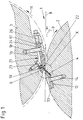
- the cross cutting device 1 shown in Figure 1 is part of a format cutter, not shown, for cutting sheets of paper, cardboard or the like.
- the device designed as a synchronous cross cutter has a lower knife drum 2 and an upper knife drum 3 as knife carriers, each of which is equipped with a number of relatively thin knives 4 and 6, of which only one is shown on each knife drum.
- a paper web 8 moving in the conveying direction 7 two knives 4 and 6 each come into cutting engagement when the two knife drums 2 and 3 rotate in the direction of the arrows 9 and 11, respectively.
- the knives 4 and 6 extend perpendicularly to the plane of drawing or in the longitudinal direction of the knife drums 2 and 3, respectively, in a slightly helical manner, the knife 4 being fastened lying in a circumferential recess or pocket 12 of the knife drum 2 by means of one or more clamping strips 13 and clamping bolts 14 arranged in a row .
- the upper knife 6 is also fastened lying in a circumferential recess or pocket 16 of the knife drum 3 by means of one or more clamping strips 17 and clamping bolts 18 lined up with one another, the knife 6 being supported with its one broad side on a contact surface 19 of the knife drum 3 and with it one Sliding surface guidance forms. With its counter-wide side, the knife 6 is positively connected to the terminal strip 17 according to FIG.
- the clamping bolts 18 penetrate the terminal strip 17 at the rear end in an opening 24 which is enlarged relative to the bolt diameter, the terminal strip 17 within the scope of movement of the bolt opening 24 by means of pressure bolts 26 acting on its rear end along an essentially tangent-parallel clamping and sliding surface 27 of the knife drum 3 is adjustable with its inclined wedge surface 23 taking the knife 6, which is advanced along its sliding guide on the contact surface 19 against the lower knife 4 and is set helically free of play over its length.
- the knife 6, which is designed as a relatively thin disposable knife, is advanced to the outside by the elastic transverse deformation of the relatively long front end of the clamping bar 17 along the contact surface 19, which is caused by the rear pressurization of the clamping bar 17 while overcoming the rear tensioning force of the clamping bar 18.
- the knife drum 203 designed as a plastic shaft (CFRP shaft). Only the one at Knife clamping and shifting elements, such as the Contact surface 219 of the knife 206 and the sliding surface 227 for the rear end the terminal block 217 are separate, also receiving the pressure bolts 226 Metal parts inserted into the plastic shaft 203.
Landscapes
- Life Sciences & Earth Sciences (AREA)
- Forests & Forestry (AREA)
- Engineering & Computer Science (AREA)
- Mechanical Engineering (AREA)
- Perforating, Stamping-Out Or Severing By Means Other Than Cutting (AREA)
- Making Paper Articles (AREA)
- Nonmetal Cutting Devices (AREA)
- Folding Of Thin Sheet-Like Materials, Special Discharging Devices, And Others (AREA)
- Treatment Of Fiber Materials (AREA)
- Details Of Cutting Devices (AREA)
Applications Claiming Priority (2)
| Application Number | Priority Date | Filing Date | Title |
|---|---|---|---|
| DE19807111A DE19807111A1 (de) | 1998-02-20 | 1998-02-20 | Messertrommel für Maschinen zum Querschneiden von Materialbahnen |
| DE19807111 | 1998-02-20 |
Publications (3)
| Publication Number | Publication Date |
|---|---|
| EP0937552A2 true EP0937552A2 (fr) | 1999-08-25 |
| EP0937552A3 EP0937552A3 (fr) | 2002-02-06 |
| EP0937552B1 EP0937552B1 (fr) | 2004-05-12 |
Family
ID=7858373
Family Applications (1)
| Application Number | Title | Priority Date | Filing Date |
|---|---|---|---|
| EP99102362A Expired - Lifetime EP0937552B1 (fr) | 1998-02-20 | 1999-02-06 | Cylindre de coupe pour une machine de coupe transversale de matériaux en bande |
Country Status (7)
| Country | Link |
|---|---|
| US (1) | US6263775B1 (fr) |
| EP (1) | EP0937552B1 (fr) |
| AT (1) | ATE266507T1 (fr) |
| AU (1) | AU743328B2 (fr) |
| CA (1) | CA2262339C (fr) |
| DE (2) | DE19807111A1 (fr) |
| ES (1) | ES2218886T3 (fr) |
Cited By (1)
| Publication number | Priority date | Publication date | Assignee | Title |
|---|---|---|---|---|
| CN108556036A (zh) * | 2018-04-18 | 2018-09-21 | 钱立文 | 无极调节的薄膜分切机切刀调节装置 |
Families Citing this family (6)
| Publication number | Priority date | Publication date | Assignee | Title |
|---|---|---|---|---|
| EP1379349A4 (fr) * | 2001-03-29 | 2006-05-31 | Showa Denko Kk | Appareil de cisaillement de plaque, procede de cisaillement de plaque et piece de plaque cisaillee |
| CA2686670C (fr) | 2002-01-17 | 2012-09-25 | Iggesund Tools Ab | Couteau a travailler le bois polyvalent et dispositif de serrage |
| US7836923B2 (en) * | 2002-10-25 | 2010-11-23 | Key Knife, Inc. | Ring slicer with easily removable knife and knife assembly |
| DE10359025A1 (de) * | 2003-12-15 | 2005-07-14 | Joachim Kozlowski | Messerleiste |
| FI12451U1 (fi) * | 2019-05-15 | 2019-08-15 | Valmet Technologies Oy | Teräjärjestely ja poikkileikkauslaite |
| CN110199609A (zh) * | 2019-06-11 | 2019-09-06 | 山东思代尔农业装备有限公司 | 马铃薯种薯制备切块机纵切装置 |
Family Cites Families (20)
| Publication number | Priority date | Publication date | Assignee | Title |
|---|---|---|---|---|
| US3030841A (en) * | 1958-12-18 | 1962-04-24 | Koppers Co Inc | Blade mounting |
| US3606811A (en) * | 1970-06-30 | 1971-09-21 | Hallden Machine Co | Rotary shear |
| US3709077A (en) * | 1971-03-01 | 1973-01-09 | Bretting C Mfg Co Inc | Cut-off device |
| DE2208687B1 (de) * | 1972-02-24 | 1973-06-14 | Hombak Maschinenfab Kg | Messerwelle für Holzbearbeitungsmaschinen |
| US3854511A (en) * | 1972-04-24 | 1974-12-17 | Maier Kg Maschf B | Blade holder for steel strip blades |
| US3822625A (en) * | 1973-02-09 | 1974-07-09 | Westvaco Corp | Rotary cutter with quick change knife |
| US3957094A (en) * | 1973-07-23 | 1976-05-18 | Maschinenfabrik G. Maier Kg | Rotary material removing tool with expendable blades |
| CA1040072A (fr) * | 1975-07-14 | 1978-10-10 | Arnold Schmidt | Arbre porte-outil pour machine a bois |
| GB1509824A (en) * | 1976-02-19 | 1978-05-04 | Amf Inc | Rotary cutting machine having a knife growth detector |
| US4159661A (en) * | 1977-07-05 | 1979-07-03 | Egan Machinery Company | Rotary cutter |
| US4467687A (en) * | 1981-12-29 | 1984-08-28 | Special Products Engineering Corporation | Alignment system for a rotary cutter |
| SE9102796L (sv) * | 1991-09-25 | 1993-03-26 | Iggesund Tools Ab | Anordning vid fraeshuvuden |
| DE9213466U1 (de) * | 1992-10-07 | 1993-01-07 | Gebr. Leitz GmbH & Co, 73447 Oberkochen | Messerkopf |
| US5271440A (en) * | 1993-02-24 | 1993-12-21 | Pacific/Hoe Saw And Knife Company | Chipper disc assembly having extended-life regrindable disposable knives |
| DE4321163C3 (de) * | 1993-06-25 | 2000-07-13 | Freudenberg Carl Fa | Querschneider |
| US5439039A (en) * | 1994-08-30 | 1995-08-08 | Pacific Saw And Knife Company | Slabber with fixed counterknife and adjustable knife and clamp |
| JP3132742B2 (ja) * | 1994-10-04 | 2001-02-05 | 株式会社小林製作所 | 切断装置 |
| JPH0899292A (ja) * | 1994-10-04 | 1996-04-16 | Kobayashi Seisakusho:Kk | 切断装置 |
| US5505239A (en) * | 1995-03-14 | 1996-04-09 | U.S. Natural Resources | Blade arrangement and blade holder for chipper |
| DE29512032U1 (de) * | 1995-07-26 | 1995-09-28 | E.C.H. Will Gmbh, 22529 Hamburg | Querschneideeinrichtung für Bahnmaterial aus Papier o.dgl. |
-
1998
- 1998-02-20 DE DE19807111A patent/DE19807111A1/de not_active Withdrawn
-
1999
- 1999-02-06 AT AT99102362T patent/ATE266507T1/de active
- 1999-02-06 ES ES99102362T patent/ES2218886T3/es not_active Expired - Lifetime
- 1999-02-06 EP EP99102362A patent/EP0937552B1/fr not_active Expired - Lifetime
- 1999-02-06 DE DE59909434T patent/DE59909434D1/de not_active Expired - Lifetime
- 1999-02-17 AU AU17361/99A patent/AU743328B2/en not_active Ceased
- 1999-02-22 US US09/253,796 patent/US6263775B1/en not_active Expired - Lifetime
- 1999-02-22 CA CA002262339A patent/CA2262339C/fr not_active Expired - Fee Related
Cited By (2)
| Publication number | Priority date | Publication date | Assignee | Title |
|---|---|---|---|---|
| CN108556036A (zh) * | 2018-04-18 | 2018-09-21 | 钱立文 | 无极调节的薄膜分切机切刀调节装置 |
| CN108556036B (zh) * | 2018-04-18 | 2019-10-01 | 钱立文 | 无极调节的薄膜分切机切刀调节装置 |
Also Published As
| Publication number | Publication date |
|---|---|
| DE19807111A1 (de) | 1999-08-26 |
| ES2218886T3 (es) | 2004-11-16 |
| ATE266507T1 (de) | 2004-05-15 |
| EP0937552B1 (fr) | 2004-05-12 |
| EP0937552A3 (fr) | 2002-02-06 |
| AU743328B2 (en) | 2002-01-24 |
| CA2262339A1 (fr) | 1999-08-20 |
| CA2262339C (fr) | 2007-04-24 |
| DE59909434D1 (de) | 2004-06-17 |
| AU1736199A (en) | 1999-09-02 |
| US6263775B1 (en) | 2001-07-24 |
Similar Documents
| Publication | Publication Date | Title |
|---|---|---|
| DE102005044128B4 (de) | Handwerkzeug | |
| DE3805379C2 (fr) | ||
| EP1551214A1 (fr) | Barre de coupe | |
| DE2627972C2 (de) | Schwenkbiegemaschine | |
| DE69315337T2 (de) | Maschine zum schneiden von bogen aus einer papierbahn und zum gleichzeitigen schneiden eines querstreifens | |
| WO2010010169A1 (fr) | Outil de coupe pour sectionner des pièces en forme de plaques | |
| DE2834696C2 (de) | Vorrichtung zum Zerschneiden einer endlosen bedruckten Papierbahn in Einzelbogen | |
| EP2295178B1 (fr) | Machine de traitement du bois avec module d'élargissement de table approprié | |
| EP0937552A2 (fr) | Cylindre de coupe pour une machine de coupe transversale de matériaux en bande | |
| EP0963820A1 (fr) | Couteau | |
| DE3141248A1 (de) | "motorbetreibbarer schraubenzieher" | |
| DE102008033425A1 (de) | Stranggranulator mit Schneidspaltverstellung | |
| EP0546392A1 (fr) | Lame pour le découpage ainsi que dispositif avec celle-ci | |
| DE19702407A1 (de) | Schnellspannvorrichtung an einer Werkstück-Bearbeitungsmaschine | |
| DE1552612C3 (de) | Schneidemaschine für Stabmateria] | |
| DE102008001399A1 (de) | Sägeblatt mit Sollbruchstellen | |
| CH695331A5 (de) | Vorrichtung zum Schneiden von polsterartigen Verpackungsmaterial. | |
| DE19711235A1 (de) | Vorrichtung für die Produktauslage mit einem Produktaufnahmebereich | |
| EP1475335A1 (fr) | Plieuse avec au moins une paire d'arbres équipés de lames | |
| DE69805137T2 (de) | Taschenmesser | |
| DE202008016612U1 (de) | Längsschneidemaschine mit variabler Einstellung der Messer-Schneidpunkte | |
| DE3116527A1 (de) | Geraet zum schneiden von schleifpapierstuecken | |
| DE2822771C2 (de) | Vorrichtung zum Herstellen von an den Stirnseiten angefasten Dübeln aus runden Holzstäben | |
| DE4207440C2 (de) | Längsschneidmaschine für eine Wellpappenbahn | |
| DE2617278C3 (de) | Messerhalterung bei einem Messerringzerspaner |
Legal Events
| Date | Code | Title | Description |
|---|---|---|---|
| PUAI | Public reference made under article 153(3) epc to a published international application that has entered the european phase |
Free format text: ORIGINAL CODE: 0009012 |
|
| AK | Designated contracting states |
Kind code of ref document: A2 Designated state(s): AT BE CH CY DE DK ES FI FR GB GR IE IT LI LU MC NL PT SE Kind code of ref document: A2 Designated state(s): AT CH DE ES FI FR GB IT LI |
|
| AX | Request for extension of the european patent |
Free format text: AL;LT;LV;MK;RO;SI |
|
| PUAL | Search report despatched |
Free format text: ORIGINAL CODE: 0009013 |
|
| AK | Designated contracting states |
Kind code of ref document: A3 Designated state(s): AT BE CH CY DE DK ES FI FR GB GR IE IT LI LU MC NL PT SE |
|
| AX | Request for extension of the european patent |
Free format text: AL;LT;LV;MK;RO;SI |
|
| 17P | Request for examination filed |
Effective date: 20020726 |
|
| AKX | Designation fees paid |
Free format text: AT CH DE ES FI FR GB IT LI |
|
| 17Q | First examination report despatched |
Effective date: 20030313 |
|
| GRAP | Despatch of communication of intention to grant a patent |
Free format text: ORIGINAL CODE: EPIDOSNIGR1 |
|
| GRAS | Grant fee paid |
Free format text: ORIGINAL CODE: EPIDOSNIGR3 |
|
| GRAA | (expected) grant |
Free format text: ORIGINAL CODE: 0009210 |
|
| AK | Designated contracting states |
Kind code of ref document: B1 Designated state(s): AT CH DE ES FI FR GB IT LI |
|
| REG | Reference to a national code |
Ref country code: GB Ref legal event code: FG4D Free format text: NOT ENGLISH |
|
| REG | Reference to a national code |
Ref country code: CH Ref legal event code: EP |
|
| GBT | Gb: translation of ep patent filed (gb section 77(6)(a)/1977) |
Effective date: 20040512 |
|
| REG | Reference to a national code |
Ref country code: IE Ref legal event code: FG4D Free format text: GERMAN |
|
| REF | Corresponds to: |
Ref document number: 59909434 Country of ref document: DE Date of ref document: 20040617 Kind code of ref document: P |
|
| REG | Reference to a national code |
Ref country code: ES Ref legal event code: FG2A Ref document number: 2218886 Country of ref document: ES Kind code of ref document: T3 |
|
| REG | Reference to a national code |
Ref country code: IE Ref legal event code: FD4D |
|
| ET | Fr: translation filed | ||
| PG25 | Lapsed in a contracting state [announced via postgrant information from national office to epo] |
Ref country code: LI Free format text: LAPSE BECAUSE OF NON-PAYMENT OF DUE FEES Effective date: 20050228 Ref country code: CH Free format text: LAPSE BECAUSE OF NON-PAYMENT OF DUE FEES Effective date: 20050228 |
|
| PLBE | No opposition filed within time limit |
Free format text: ORIGINAL CODE: 0009261 |
|
| STAA | Information on the status of an ep patent application or granted ep patent |
Free format text: STATUS: NO OPPOSITION FILED WITHIN TIME LIMIT |
|
| 26N | No opposition filed |
Effective date: 20050215 |
|
| REG | Reference to a national code |
Ref country code: CH Ref legal event code: PL |
|
| PGFP | Annual fee paid to national office [announced via postgrant information from national office to epo] |
Ref country code: FR Payment date: 20100225 Year of fee payment: 12 Ref country code: FI Payment date: 20100218 Year of fee payment: 12 |
|
| PGFP | Annual fee paid to national office [announced via postgrant information from national office to epo] |
Ref country code: GB Payment date: 20100217 Year of fee payment: 12 |
|
| GBPC | Gb: european patent ceased through non-payment of renewal fee |
Effective date: 20110206 |
|
| REG | Reference to a national code |
Ref country code: FR Ref legal event code: ST Effective date: 20111102 |
|
| PG25 | Lapsed in a contracting state [announced via postgrant information from national office to epo] |
Ref country code: FI Free format text: LAPSE BECAUSE OF NON-PAYMENT OF DUE FEES Effective date: 20110206 |
|
| PG25 | Lapsed in a contracting state [announced via postgrant information from national office to epo] |
Ref country code: FR Free format text: LAPSE BECAUSE OF NON-PAYMENT OF DUE FEES Effective date: 20110228 |
|
| PG25 | Lapsed in a contracting state [announced via postgrant information from national office to epo] |
Ref country code: GB Free format text: LAPSE BECAUSE OF NON-PAYMENT OF DUE FEES Effective date: 20110206 |
|
| REG | Reference to a national code |
Ref country code: DE Ref legal event code: R081 Ref document number: 59909434 Country of ref document: DE Owner name: E.C.H. WILL GMBH, DE Free format text: FORMER OWNER: E.C.H. WILL GMBH, 22529 HAMBURG, DE Effective date: 20120323 |
|
| PGFP | Annual fee paid to national office [announced via postgrant information from national office to epo] |
Ref country code: DE Payment date: 20170227 Year of fee payment: 19 |
|
| PGFP | Annual fee paid to national office [announced via postgrant information from national office to epo] |
Ref country code: AT Payment date: 20170216 Year of fee payment: 19 |
|
| PGFP | Annual fee paid to national office [announced via postgrant information from national office to epo] |
Ref country code: IT Payment date: 20170228 Year of fee payment: 19 Ref country code: ES Payment date: 20170224 Year of fee payment: 19 |
|
| REG | Reference to a national code |
Ref country code: DE Ref legal event code: R119 Ref document number: 59909434 Country of ref document: DE |
|
| REG | Reference to a national code |
Ref country code: AT Ref legal event code: MM01 Ref document number: 266507 Country of ref document: AT Kind code of ref document: T Effective date: 20180206 |
|
| PG25 | Lapsed in a contracting state [announced via postgrant information from national office to epo] |
Ref country code: AT Free format text: LAPSE BECAUSE OF NON-PAYMENT OF DUE FEES Effective date: 20180206 |
|
| PG25 | Lapsed in a contracting state [announced via postgrant information from national office to epo] |
Ref country code: DE Free format text: LAPSE BECAUSE OF NON-PAYMENT OF DUE FEES Effective date: 20180901 |
|
| PG25 | Lapsed in a contracting state [announced via postgrant information from national office to epo] |
Ref country code: IT Free format text: LAPSE BECAUSE OF NON-PAYMENT OF DUE FEES Effective date: 20180206 |
|
| REG | Reference to a national code |
Ref country code: ES Ref legal event code: FD2A Effective date: 20190801 |
|
| PG25 | Lapsed in a contracting state [announced via postgrant information from national office to epo] |
Ref country code: ES Free format text: LAPSE BECAUSE OF NON-PAYMENT OF DUE FEES Effective date: 20180207 |