EP0937593B1 - Dispositif pour loger un capuchon de protection - Google Patents
Dispositif pour loger un capuchon de protection Download PDFInfo
- Publication number
- EP0937593B1 EP0937593B1 EP98117929A EP98117929A EP0937593B1 EP 0937593 B1 EP0937593 B1 EP 0937593B1 EP 98117929 A EP98117929 A EP 98117929A EP 98117929 A EP98117929 A EP 98117929A EP 0937593 B1 EP0937593 B1 EP 0937593B1
- Authority
- EP
- European Patent Office
- Prior art keywords
- protective cap
- cap carrier
- carrier system
- base section
- hose clamp
- Prior art date
- Legal status (The legal status is an assumption and is not a legal conclusion. Google has not performed a legal analysis and makes no representation as to the accuracy of the status listed.)
- Expired - Lifetime
Links
- 230000001681 protective effect Effects 0.000 title claims description 63
- 230000008878 coupling Effects 0.000 claims description 7
- 238000010168 coupling process Methods 0.000 claims description 7
- 238000005859 coupling reaction Methods 0.000 claims description 7
- 239000011324 bead Substances 0.000 claims description 4
- 229920003023 plastic Polymers 0.000 claims description 3
- 239000004033 plastic Substances 0.000 claims description 3
- 230000003014 reinforcing effect Effects 0.000 abstract description 2
- 235000001674 Agaricus brunnescens Nutrition 0.000 abstract 1
- 238000013461 design Methods 0.000 description 4
- 235000003332 Ilex aquifolium Nutrition 0.000 description 3
- 241000209027 Ilex aquifolium Species 0.000 description 3
- 230000002787 reinforcement Effects 0.000 description 3
- 210000002105 tongue Anatomy 0.000 description 2
- 230000004308 accommodation Effects 0.000 description 1
- 230000006978 adaptation Effects 0.000 description 1
- 230000005540 biological transmission Effects 0.000 description 1
- 230000007797 corrosion Effects 0.000 description 1
- 238000005260 corrosion Methods 0.000 description 1
- 238000003780 insertion Methods 0.000 description 1
- 230000037431 insertion Effects 0.000 description 1
- 238000004519 manufacturing process Methods 0.000 description 1
- 238000000034 method Methods 0.000 description 1
- 238000012545 processing Methods 0.000 description 1
- 238000012549 training Methods 0.000 description 1
Images



Classifications
-
- B—PERFORMING OPERATIONS; TRANSPORTING
- B60—VEHICLES IN GENERAL
- B60D—VEHICLE CONNECTIONS
- B60D1/00—Traction couplings; Hitches; Draw-gear; Towing devices
- B60D1/58—Auxiliary devices
- B60D1/60—Covers, caps or guards, e.g. comprising anti-theft devices
- B60D1/605—Protection caps
-
- B—PERFORMING OPERATIONS; TRANSPORTING
- B60—VEHICLES IN GENERAL
- B60D—VEHICLE CONNECTIONS
- B60D1/00—Traction couplings; Hitches; Draw-gear; Towing devices
- B60D1/58—Auxiliary devices
- B60D1/60—Covers, caps or guards, e.g. comprising anti-theft devices
Definitions
- the present invention relates to a protective cap carrier system for the cover of a motor vehicle trailer coupling.
- a protective cap carrier system according to the generic term of claim 1 is from the document DE-U-90 02 631 has become known.
- the present invention is therefore based on the object to create a protective cap carrier system that the Overcomes disadvantages of the prior art and is effective Receptacle for the protective cap creates when the trailer hitch is in operation.
- the base section at its lower end has annular outer reinforcing bead a particularly stable design of the protective cap carrier system reached.
- the transmission required in this area the clamping force is achieved particularly well and by the sleeve-shaped design of the body created a particularly light embodiment.
- the end face of the base section is advantageously gabled formed, the gable extending into the interior of the Base section extends. This serves in excellent Way for attaching the protective cap support system a round bar of the drawbar.
- the end face of the base section be arched, the arch being in the Extends inside the base portion.
- the Head section at its top a flattening. there is particularly easy to manufacture Form reached.
- cap carrier body Furthermore, there is advantageously a simple and effective attachment of the cap carrier body in that the hose clamp from a standard plastic hose clamp is formed. This shows sufficient Firmness to secure the cap carrier to the drawbar of the trailer.
- the base section of the sleeve-shaped body have an internal thread that a corresponding threaded bolt can be screwed on is attached to the drawbar of the trailer.
- a retaining pin can also be provided be on which the sleeve-shaped body can be plugged, wherein the holding pin has a passage opening for the passage the hose clamp has.
- the retaining pin is arranged stationary on the drawbar of the trailer, so that a position securing of the cap carrier is created.
- Protective cap carrier system has a protective cap carrier Clamping device with which he is on the edge of a plate or wall of a U-shaped spar, for example is.
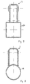
- Figure 1 is a sectional view of an inventive Protective cap carrier system with a protective cap carrier 3 shown. This view follows the line I-I of Figure 2.
- the protective cap carrier 3 a base section 5 and a head section 7 on.
- the protective cap carrier 3 is sleeve-shaped formed, the head portion by a wall reinforcement of the base portion 5 is formed, and the Head section 7 on its upper side through a flat 9 is limited.
- the Protective cap carrier 3 In its lower area of the base section 5 the Protective cap carrier 3 two rectangular passage openings 11, which serve a commercial Take up hose clamp.
- annular one Bead 13 is provided, which represents a wall reinforcement.
- the lower area of the base section 5 is gabled formed, the gable 15 in the interior of the Protective cap carrier 3 extends.
- FIGS. 3 and 4 of the protective cap holder according to the invention An alternative embodiment is shown in FIGS. 3 and 4 of the protective cap holder according to the invention.
- This alternative embodiment of a protective cap carrier 23 has, similar to the embodiment of Figures 1 and 2 a base section 5, a head section 7, a flat 9, and two through openings 11 and one Reinforcement bead 13 on.
- the end face 25 of the lower End region of the base section 5 is flat.
- Figure 3 shows a section along the line III-III of Figure 4th
- FIGS of the present invention Another alternative embodiment is shown in FIGS of the present invention. In turn are the same elements of all embodiments with the same Designated reference numbers.
- the protective cap carrier 33 according to FIGS. 5 and 6 is a curved one Face 35 on. This is also used for attachment the cap holder on a round bar one Drawbar of a tow bar.
- Figure 7 is an attachment of the invention Protective cap support system on a rectangular spar 27 shown. It is the embodiment according to FIGS. 3 and 4.
- Figure 8 is an attachment of the invention Protective cap carrier 3 on a round bar 17 of a trailer drawbar shown.
- FIG. 9 shows another alternative of the invention Protective cap carrier system shown.
- the protective cap holder 43 has a clamping device 45 with which it on the edge of a plate or wall 47 of a U-shaped Drawbar 46 can be plugged on. Doing so will essentially semicircular edge 6 of the base section 5 with a Incision 49 provided so that two arcuate tongues 51st be formed.
- the incision 49 tapers in the process from the outside in through a bevel of the tongue 51, whereby an adaptation of the clamping device 45 to the wall thickness the wall 47 without additional tools and processing is made possible.
Landscapes
- Engineering & Computer Science (AREA)
- Transportation (AREA)
- Mechanical Engineering (AREA)
- Fittings On The Vehicle Exterior For Carrying Loads, And Devices For Holding Or Mounting Articles (AREA)
- Pinball Game Machines (AREA)
- Buffer Packaging (AREA)
- Protection Of Pipes Against Damage, Friction, And Corrosion (AREA)
Claims (10)
- Système de support de capuchon de protection pour une couverture d'une attache de remorque de véhicule automobile, comportant un support de capuchon de protection (3 ; 23 ; 33 ; 43), qui présente un pourtour extérieur en forme de champignon, dans lequel le support de capuchon de protection (3 ; 23 ; 33 ; 43) est réalisée en forme de gaine ou en forme de capuchon et présente une section de tête (7) et une section de base (5) cylindrique, caractérisé en ce que dans la section d'extrémité du corps opposée à la section de tête (7) sont prévus en regard l'un de l'autre au moins deux orifices (11), qui servent à loger une pince pour tuyau par laquelle le support de capuchon de protection (3 ; 23 ; 33 ; 43) peut être fixé au timon de la remorque.
- Système de support de capuchon de protection selon la revendication 1, caractérisé en ce que la section de base (5) présente à son extrémité inférieure un bourrelet de renfort extérieur (13) annulaire.
- Système de support de capuchon de protection selon la revendication 1 ou 2, caractérisé en ce que la face frontale (15) de la section de base (5) est réalisée à la manière d'un pignon, le pignon s'étendant à l'intérieur de la section de base (5).
- Système de support de capuchon de protection selon la revendication 1 ou 2, caractérisé en ce que la face frontale (35) de la section de base (5) est réalisée en forme d'arc, l'arc s'étendant à l'intérieur de la section de base (5).
- Système de support de capuchon de protection selon la revendication 1 ou 2, caractérisé en ce que la face frontale (25) de la section de base (5) est sensiblement plane.
- Système de support de capuchon de protection selon l'une des revendications 1 à 5, caractérisé en ce que la section de tête (7) est aplatie (9) sur le côté supérieur.
- Système de support de capuchon de protection selon l'une des revendications 1 à 6, caractérisé en ce que la pince pour tuyau est constituée par une pince pour tuyau courante du commerce, en particulier en matière plastique.
- Système de support de capuchon de protection selon l'une des revendications 1 à 6, caractérisé en ce que la section de base (5) du corps en forme de gaine présente un taraudage, lequel peut être vissé sur un boulon fileté correspondant.
- Système de support de capuchon de protection selon l'une des revendications 1 à 7, caractérisé en ce que le support de capuchon de protection (3 ; 23 ; 33) peut être emboíté sur un téton de maintien, qui présente un orifice de passage pour le passage de la pince pour tuyau.
- Système de support de capuchon de protection selon l'une des revendications 2, 6 ou 7, caractérisé en ce que le support de capuchon de protection (43) présente un dispositif de serrage par lequel il peut être emboíté sur le bord d'une plaque ou paroi (47).
Applications Claiming Priority (2)
| Application Number | Priority Date | Filing Date | Title |
|---|---|---|---|
| DE29802603U DE29802603U1 (de) | 1998-02-18 | 1998-02-18 | Schutzkappenträgersystem |
| DE29802603U | 1998-02-18 |
Publications (2)
| Publication Number | Publication Date |
|---|---|
| EP0937593A1 EP0937593A1 (fr) | 1999-08-25 |
| EP0937593B1 true EP0937593B1 (fr) | 2002-08-14 |
Family
ID=8052712
Family Applications (1)
| Application Number | Title | Priority Date | Filing Date |
|---|---|---|---|
| EP98117929A Expired - Lifetime EP0937593B1 (fr) | 1998-02-18 | 1998-09-22 | Dispositif pour loger un capuchon de protection |
Country Status (3)
| Country | Link |
|---|---|
| EP (1) | EP0937593B1 (fr) |
| AT (1) | ATE222187T1 (fr) |
| DE (2) | DE29802603U1 (fr) |
Families Citing this family (3)
| Publication number | Priority date | Publication date | Assignee | Title |
|---|---|---|---|---|
| DE60205055T2 (de) * | 2001-04-14 | 2006-05-24 | Interforst K/S | Schutzkappe für eine Kugelkopfkupplung |
| CA3048695A1 (fr) * | 2018-07-11 | 2020-01-11 | Process4, Inc. | Couvercle de protection d`un joint a rotule a utiliser sur des attaches de remorque |
| DE202018005658U1 (de) | 2018-12-06 | 2019-03-11 | Herbert Kraßmann | Trägersystem zur Aufnahme einer Schutzkappe von Kugelkopfkupplungen |
Family Cites Families (6)
| Publication number | Priority date | Publication date | Assignee | Title |
|---|---|---|---|---|
| DE1926607U (de) * | 1965-08-17 | 1965-11-04 | Johannes Apprich Bau Kunststof | Wetterfeste abdeckkappe aus kunststoff fuer anhaengerkupplungen. |
| DE8518027U1 (de) * | 1985-06-21 | 1985-09-05 | Römpke, Heinz-Hubert, 2409 Scharbeutz | Abdeckkappe mit Halterung für Anhängerkupplungen von Kraftfahrzeugen |
| DE8619683U1 (de) * | 1986-07-21 | 1986-09-18 | Ramfft, Torsten, 1000 Berlin | Schutzkappe für den Kugelkopf einer Kfz-Anhängerkupplung |
| US4955968A (en) * | 1988-10-17 | 1990-09-11 | Beckerer Frank S Jr | Protective cover for a trailer hitch |
| DE9002631U1 (de) * | 1990-03-07 | 1990-05-10 | Grimm, Werner, 7070 Schwäbisch Gmünd | Vorrichtung zur Aufnahme einer Schutzkappe |
| DE9201445U1 (de) | 1992-02-06 | 1992-05-27 | Hastrich, Hans-Peter, 5439 Kölbingen | Kappenträger |
-
1998
- 1998-02-18 DE DE29802603U patent/DE29802603U1/de not_active Expired - Lifetime
- 1998-09-22 EP EP98117929A patent/EP0937593B1/fr not_active Expired - Lifetime
- 1998-09-22 AT AT98117929T patent/ATE222187T1/de not_active IP Right Cessation
- 1998-09-22 DE DE59805181T patent/DE59805181D1/de not_active Expired - Fee Related
Also Published As
| Publication number | Publication date |
|---|---|
| ATE222187T1 (de) | 2002-08-15 |
| EP0937593A1 (fr) | 1999-08-25 |
| DE59805181D1 (de) | 2002-09-19 |
| DE29802603U1 (de) | 1998-04-23 |
Similar Documents
| Publication | Publication Date | Title |
|---|---|---|
| DE69920305T2 (de) | Diebstahlsicherungsmarkierer für Artikel mit stabförmigen Teilen | |
| DE29507890U1 (de) | Abdeckung für ein Gassackrückhaltesystem in Fahrzeugen | |
| DE102016110748B3 (de) | Klappgelenk für Rückblickanzeigevorrichtung | |
| DE69802376T2 (de) | Fahrzeugabschleppvorrichtung mit abnehmbarer Kugelkopfkupplung, selbsttätiger Vorrichtung und Stromsteckdose | |
| DE3722091C2 (fr) | ||
| DE69103038T2 (de) | Metallschneidwerkzeug. | |
| DE19521896A1 (de) | Anhängevorrichtung für insbesondere Personenkraftwagen | |
| EP0937593A1 (fr) | Dispositif pour loger un capuchon de protection | |
| EP0713810B1 (fr) | Essuie-glace avec lame d'essuie-glace échangeable | |
| DE9212243U1 (de) | Mülltonne mit einem der Mülltonnen-Identifikation dienenden Transponder | |
| EP0318653B1 (fr) | Dispositif pour le blocage d'un attelage de remorque équipé d'un dispositif antiroulis | |
| DE29805326U1 (de) | Griffhülle für einen Papiertaschengriff | |
| DE3872825T2 (de) | Kugelsensor fuer sicherheitsgurtaufroller, insbesondere fuer kraftfahrzeuge. | |
| DE68912698T2 (de) | Reserveradabdeckung. | |
| DE3338963C2 (de) | Verkleidungsclip | |
| DE3233946C2 (de) | Parkplatz-Absperrpfosten | |
| EP0445717A1 (fr) | Dispositif pour loger un capuchon de protection | |
| DE3743301C2 (fr) | ||
| EP0340614B1 (fr) | Attelage pour camions, véhicules agricoles ou similaires | |
| DE8702644U1 (de) | Zusatzeinrichtung für Kugelkopf-Anhängerkupplungen | |
| EP0093795A1 (fr) | Attelage pour vehicule à moteur | |
| DE102024002710A1 (de) | Anhängerkupplung mit einer Kameravorrichtung | |
| DE9404461U1 (de) | Distanzhalter | |
| DE8405450U1 (de) | Halterung für einen Zusatzspiegel | |
| DE19513283A1 (de) | Anhängerkupplungsvorrichtung |
Legal Events
| Date | Code | Title | Description |
|---|---|---|---|
| PUAI | Public reference made under article 153(3) epc to a published international application that has entered the european phase |
Free format text: ORIGINAL CODE: 0009012 |
|
| AK | Designated contracting states |
Kind code of ref document: A1 Designated state(s): AT BE CH DE DK ES FR IT LI NL |
|
| AX | Request for extension of the european patent |
Free format text: AL;LT;LV;MK;RO;SI |
|
| 17P | Request for examination filed |
Effective date: 20000222 |
|
| AKX | Designation fees paid |
Free format text: AT BE CH DK ES FR IT LI NL |
|
| RBV | Designated contracting states (corrected) |
Designated state(s): AT BE CH DE DK ES FR IT LI NL |
|
| REG | Reference to a national code |
Ref country code: DE Ref legal event code: 8566 |
|
| GRAG | Despatch of communication of intention to grant |
Free format text: ORIGINAL CODE: EPIDOS AGRA |
|
| 17Q | First examination report despatched |
Effective date: 20010709 |
|
| GRAG | Despatch of communication of intention to grant |
Free format text: ORIGINAL CODE: EPIDOS AGRA |
|
| GRAG | Despatch of communication of intention to grant |
Free format text: ORIGINAL CODE: EPIDOS AGRA |
|
| GRAH | Despatch of communication of intention to grant a patent |
Free format text: ORIGINAL CODE: EPIDOS IGRA |
|
| GRAH | Despatch of communication of intention to grant a patent |
Free format text: ORIGINAL CODE: EPIDOS IGRA |
|
| GRAA | (expected) grant |
Free format text: ORIGINAL CODE: 0009210 |
|
| AK | Designated contracting states |
Kind code of ref document: B1 Designated state(s): AT BE CH DE DK ES FR IT LI NL |
|
| PG25 | Lapsed in a contracting state [announced via postgrant information from national office to epo] |
Ref country code: NL Free format text: LAPSE BECAUSE OF FAILURE TO SUBMIT A TRANSLATION OF THE DESCRIPTION OR TO PAY THE FEE WITHIN THE PRESCRIBED TIME-LIMIT Effective date: 20020814 |
|
| REF | Corresponds to: |
Ref document number: 222187 Country of ref document: AT Date of ref document: 20020815 Kind code of ref document: T |
|
| REG | Reference to a national code |
Ref country code: CH Ref legal event code: EP |
|
| REF | Corresponds to: |
Ref document number: 59805181 Country of ref document: DE Date of ref document: 20020919 |
|
| PGFP | Annual fee paid to national office [announced via postgrant information from national office to epo] |
Ref country code: CH Payment date: 20021001 Year of fee payment: 5 |
|
| PG25 | Lapsed in a contracting state [announced via postgrant information from national office to epo] |
Ref country code: DK Free format text: LAPSE BECAUSE OF FAILURE TO SUBMIT A TRANSLATION OF THE DESCRIPTION OR TO PAY THE FEE WITHIN THE PRESCRIBED TIME-LIMIT Effective date: 20021114 |
|
| ET | Fr: translation filed | ||
| NLV1 | Nl: lapsed or annulled due to failure to fulfill the requirements of art. 29p and 29m of the patents act | ||
| PG25 | Lapsed in a contracting state [announced via postgrant information from national office to epo] |
Ref country code: ES Free format text: LAPSE BECAUSE OF FAILURE TO SUBMIT A TRANSLATION OF THE DESCRIPTION OR TO PAY THE FEE WITHIN THE PRESCRIBED TIME-LIMIT Effective date: 20030228 |
|
| PLBE | No opposition filed within time limit |
Free format text: ORIGINAL CODE: 0009261 |
|
| STAA | Information on the status of an ep patent application or granted ep patent |
Free format text: STATUS: NO OPPOSITION FILED WITHIN TIME LIMIT |
|
| 26N | No opposition filed |
Effective date: 20030515 |
|
| PGFP | Annual fee paid to national office [announced via postgrant information from national office to epo] |
Ref country code: FR Payment date: 20030917 Year of fee payment: 6 |
|
| PGFP | Annual fee paid to national office [announced via postgrant information from national office to epo] |
Ref country code: AT Payment date: 20030919 Year of fee payment: 6 |
|
| PGFP | Annual fee paid to national office [announced via postgrant information from national office to epo] |
Ref country code: BE Payment date: 20030922 Year of fee payment: 6 |
|
| PG25 | Lapsed in a contracting state [announced via postgrant information from national office to epo] |
Ref country code: LI Free format text: LAPSE BECAUSE OF NON-PAYMENT OF DUE FEES Effective date: 20030930 Ref country code: CH Free format text: LAPSE BECAUSE OF NON-PAYMENT OF DUE FEES Effective date: 20030930 |
|
| PGFP | Annual fee paid to national office [announced via postgrant information from national office to epo] |
Ref country code: DE Payment date: 20030930 Year of fee payment: 6 |
|
| REG | Reference to a national code |
Ref country code: CH Ref legal event code: PL |
|
| PG25 | Lapsed in a contracting state [announced via postgrant information from national office to epo] |
Ref country code: AT Free format text: LAPSE BECAUSE OF NON-PAYMENT OF DUE FEES Effective date: 20040922 |
|
| PG25 | Lapsed in a contracting state [announced via postgrant information from national office to epo] |
Ref country code: BE Free format text: LAPSE BECAUSE OF NON-PAYMENT OF DUE FEES Effective date: 20040930 |
|
| BERE | Be: lapsed |
Owner name: *NAUDER KURT Effective date: 20040930 |
|
| PG25 | Lapsed in a contracting state [announced via postgrant information from national office to epo] |
Ref country code: DE Free format text: LAPSE BECAUSE OF NON-PAYMENT OF DUE FEES Effective date: 20050401 |
|
| PG25 | Lapsed in a contracting state [announced via postgrant information from national office to epo] |
Ref country code: FR Free format text: LAPSE BECAUSE OF NON-PAYMENT OF DUE FEES Effective date: 20050531 |
|
| REG | Reference to a national code |
Ref country code: FR Ref legal event code: ST |
|
| PG25 | Lapsed in a contracting state [announced via postgrant information from national office to epo] |
Ref country code: IT Free format text: LAPSE BECAUSE OF NON-PAYMENT OF DUE FEES;WARNING: LAPSES OF ITALIAN PATENTS WITH EFFECTIVE DATE BEFORE 2007 MAY HAVE OCCURRED AT ANY TIME BEFORE 2007. THE CORRECT EFFECTIVE DATE MAY BE DIFFERENT FROM THE ONE RECORDED. Effective date: 20050922 |
|
| BERE | Be: lapsed |
Owner name: *NAUDER KURT Effective date: 20040930 |